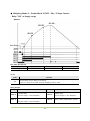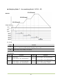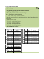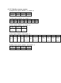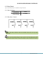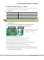
1
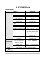
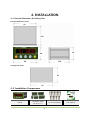
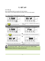
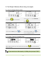
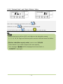
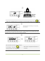
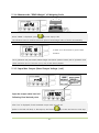
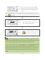
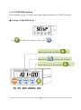
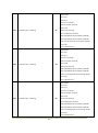
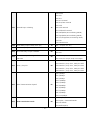
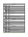
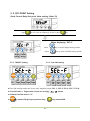
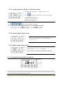
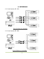
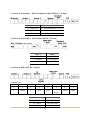
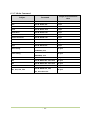
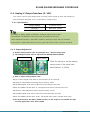
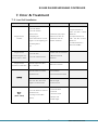
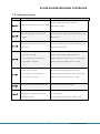
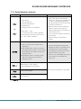
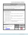
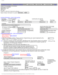
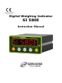
Digital Weighing Indicator SI 580E Instruction Manual CONTENTS 1. Before Installation ------------------------- 3 Page 2. Introduction ------------------------- 4 Page 3. Specification ------------------------- 5 Page 4. Installation ------------------------- 9 Page 4-1. External Dimension & Cutting Size ------------------------- 9 Page 4-2. Installation Components ------------------------- 9 Page 4-3. Load Cell Installation ------------------------- 10 Page ------------------------- 11 Page 5-1. Set Up ------------------------- 11 Page 5-2. TEST Weight Calibration Mode ------------------------- 15 Page 5-3. Simulating Calibration Mode ------------------------- 18 Page 5-4. F-FUNCTION Setting ------------------------- 22 Page 5-5 SET-POINT Setting ------------------------- 49 Page 5-6. Test Mode ------------------------- 50 Page ------------------------- 54 Page 6-1. Serial Interface ------------------------- 54 Page 6-2. Relay Output ------------------------- 68 Page 6-3. Analog Output Interface(4~20mA) ------------------------- 69 Page 6-4. Analog Output Interface(0~10V) ------------------------- 70 Page 6-5. Serial Print ------------------------- 71 Page ------------------------- 72 Page 5. Set up 6. Interface 7. Error & Treatment Warrantee Certificate -------------------------2- 75 Page 1. BEFORE INSTALLATION Caution / Warning Marks This mark warns the possibility to arrive death or serious injury in case of wrongly used. This mark cautions the possibility to arrive serious human body injury or product lose in case of wrongly used. Copy Rights 1. All Right and Authority for this Manual is belonged to SEWHA CNM CO., LTD. 2. Any kinds of copy or distribution without permission of SEWHA CNM CO., LTD. will be prohibited. 3. This manual may be changed as the version is upgraded, without previous notice. Inquiries If you have any kinds of inquiries for this model, please contact your local agent or Head Office. Head Office : SEWHA CNM CO., LTD. Website : www.sewhacnm.co.kr Email : [email protected] -3- 2. INTRODUCTION 2-1. Introduction Thank you for your choice of this SI580E Industrial Digital Weighing Controller. This SI580E model is high-performance weighing controller. SI 580E model has various kinds of “Weighing Modes” – with 4pcs Control Relay output. And it has 2ports serial interface, and Analogue Output(0~10V or 4~20mA - Selectable). Please review and learn this instruction Manual and enjoy your process efficiency with “SI 580E” Digital Weighing Controller. 2-2. Cautions 1. Don’t drop on the ground and avoid serious external damage on item. 2. Don’t install under sunshine or heavy vibrated condition. 3. Don’t install place where high voltage or heavy electric noise condition. 4. When you connect with other devices, please turn off the power of item. 5. Avoid from water damage. 6. For the improvement of function or performance, we can change item specification without previous notice or permission. 7. Item’s performance will be up-dated continuously base on previous version’s performance. 8. If the equipment is used in a manner not specified by the manufacturer, the protection provided by the equipment may be impaired. 9. If the operation environment is dusty, regular cleaning might be needed. 2-3. Features 1. SI 580E model is the standard 1/8 DIN SIZE and compact enough, so it is easy to install. 2. Front panel is covered with Polycarbonate film, strong against dust and water. 3. There are standard installed with RS-422&RS-232C or RS-485&RS-232C. 4. The user can select the analog output, 4~20mA(default) / 0~10V. -4- 3. SPECIFICATION 3-1 Specification Content Performance Specification External Resolution 1/20,000 Internal Resolution 1/2,097,152 (±1,048,576) Input Sensitivity Min. 0.1µV/V Max Signal Input Voltage 3.0mV/V Load cell Excitation DC +5V A/D Conversion Method Sigma-Delta Decimal Point 0, 0.0, 0.00, 0.000 Drift Environment Offset 10PPM/℃ Span 10PPM/℃ Linearity 0.001% of Full Scale Analogue Sampling(sec) 60times / sec(MAX) Operating Temperature Range -10℃ ~ +40℃ [14℉ ~ 104℉] Operation Humidity Range 40% ~ 85% RH, Non-condensing Test Weight Calibration Mode Calibration Mode Function Simulation Calibration Mode 6 digit, 15mm(0.6inch) Display Red Color FND Key Pad 5EA Standard Key Digital Input 4pcs Digital Input Serial Port1 (RS-422/485) Communication Power Size Serial Print, MODBUS(RTU) Data Transference, Command Mode Serial Port2 (RS-232) Control Output Data Transference, Command Mode Serial Print Analogue Output 0~10V / 4~20mA User selection Control Relay Output Card 4pcs Control Relay Input Power DC 24V Power Consumption Max 8W 96mm(W)ⅹ48mm(H)ⅹ135mm(D) Including Connector Weight : 350g -5- 3-2. Front Panel 3-2-1 Front Panel (Display / Key Pad) 3-2-1. Status Lamp STEADY When the weight is “STEADY”, Lamp is ON. ZERO When the current weight is ”ZERO”, Lamp is ON. TARE “TARE” function is set, Lamp is ON. HOLD “HOLD” function is set, Lamp is ON. OUT1 When “OUT1”(Relay) operates, Lamp is ON OUT2 When “OUT2”(Relay) operates, Lamp is ON OUT3 When “OUT3”(Relay) operates, Lamp is ON OUT4 When “OUT4”(Relay) operates, Lamp is ON -6- 3-2-2. Key Operation 1. Normal Mode : Make Weight value as Zero. 2. Calibration Mode : Cancel the value or move to previous step. 3. F-Function setting : Cancel 4. Set point setting : Cancel 1.Normal Mode : Set the TARE Function (1st input : “TARE”, 2nd input : “TARE Reset”) (When “HOLD” or weight value is ZERO, then this key doesn’t work.) 2.Calibration Mode : Move to left 3.F-Function setting : Move to left 1. To set the “HOLD” Function (1st input : “HOLD”, 2nd input : “HOLD Reset” ) 2.Calibration Mode , F-Function setting : Move to right 3. Under “SETUP” Mode, Enter into the “Calibration” Mode. 4. Go into test mode 1 5.Under HOLD setting first digit as “H” 1. Normal Mode : Print out 2.Calibration Mode , F-Function setting :Increase set value 3. Go into test mode 2 4. Set up Mode : Enter Test Mode. 5. If F-102 set 0, 4, 5, 6 able to weight data to save 1.Normal Mode : Press this key 4times, within 2secs, enter to “SET-UP” mode. 2.Hidden Mode : on pressing this key by 4 second enter to “Hidden” mode. 2.Calibration Mode : Enter 3.F-Function setting : Save the value go to next step ●Setup Mode :It is a mode can SET UP the calibration, Function list .(refer to CH5. SET UP) 3-2-3. Hot key (with F key) Continuous “TARE” setting (From the second TARE setting, use this key) If the Printer is installed, You can print out the “Grand-total data”. (GRAND-total data can be checked though Print output). Max accumulated weighing count : 999,999times Over 999,999times return to “0” time Max accumulated weight display : 999999999 (g, kg, ton) Over 999,999,999 (g, kg, ton) return to “0” (g, kg, ton) -7- 3-3 Rear Panel 5. INPUT 1.Power 6.RELAYOUT 2.INPUT 7.ANALOGUE OUT 8.SERIAL I/F 3.SERIAL I/F 4. LOAD CELL 1. Power DC IN: 24V (Power: 24V 1A recommended) 2. External Input terminal: Bottom side 2 port (Refer to F-233, 234 to select desired function of each input terminal) 3. Serial Interface terminal: Port No.1, Bottom side Communication Method TX+ Terminal TX- Terminal RX+ Terminal RX- Terminal RS – 422(Standard) TX+ TX- RX+ RX- RS – 485(Standard) Not used Not used RTX + RTX- 4. Load cell Input EXC+ EXC- SIG+ SIG- SHIELD 5. External Input terminal: Top side 2port (Refer to F235, F236 to select desired function of each input terminal) 6. Relay Output terminal RELAY COM RELAY 1 RELAY 2 RELAY 3 RELAY 4 (Output Mode will be determined by F226 ~ F229 detail) 7. Analogue Output terminal (Selectable) 4~20mA (Factory Default) + - 0~10V + - 8. Serial Interface terminal (port No,2 top side) Communication 1(from left) 2 3 4 RS – 232C(Standard) TX+ RX- GND GND RS – 485(option) RTX+ RTX- Not used Not used RS – 422(option) TX TX RX+ RX- Please check the Comm. and other specification in the label, attached on the cover plate first, and make connection according to that information. -8- 4. INSTALLATION 4-1. External Dimension & Cutting Size External Dimension (mm) 91 118 44 48 116 96 2 Cutting Size (mm) 45 93 4-2. Installation Components SI580E Connector (5EA) 3P, 5P, 7P x 3 -9- Pin terminal(15EA) User Manual 4-3. Load cell Installation Load Cell Wire Connection (In case of SEWHACNM’s Load cell) It depends on the manufacturer of load cell, please check the specification. -----Sewhacnm Co.,ltd. Load cell & wire color---- wire color can be changed without prior notice. ※ Load cell Under set up the Load cell, if EXC+ and EXC- have a short circuit, It may cause damage in the indicator.(specially analogue board) If you connect other wires to Load cell terminal wrongly, it may cause damage in the analogue board. Before connecting the load cell cable you have to power off and be sure to connect the cable to the terminal correctly. Do not weld near the load cells , Indicators or other devices. ■ Installation The Load cells 1. You can connect Max 8pcs of same capacity Load cells at once. (350 Ω) 2. You have to make horizontal balance on the ground. 3. If you install more than 2pcs of load cells, use Summing box and adjust output signal difference as minimum. It can make wrong weighing process caused by each load cell’s variation. 4. If there is some temperature difference around Load cell, it can cause wrong weight measurement. 5. Don’t do Welding job or Arc discharge around installation place. But, there is no choice, please disconnect power cable and Load cell cable. 6. If you measure static electricity material, please make earth between down part and up part of Load cell. - 10 - 5. SET-UP 5-1. Set up This is the Menu which can set the all of the functions. There may be some display differences between real and on the manual. 5-1-1. Start “SET UP” Mode (Password not used) 51580e 5et-Up When “SET UP” is displayed, SETUP Mode is Press key four times within 2sec. activated. Start “SET UP” Mode (Password Use – Refer Hidden Option HF07) 51580e Press key four times within 2sec. p-Uj If “P-W” displays, input 4 characters password. 5et-Up If Password is right, “SETUP” Mode starts. 0.000 If Password is wrong, it is back to weighing display. If you set password by “HF07”, “TEST” mode, you cannot start “SETUP” Mode without password. Please don’t forget the pass word. - 11 - To Go Each Mode Weight Calibration Calibration key for 4 seconds Pass word Simulation Calibration F-FUNCTION Mode Analog value key for 4 seconds Pass word key 4 times key 4 times key 4 times key 4 times key 4 times key 4 times key 4 times key 4 times key 4 times key 4 times key 4 times Analog Test Mode1 difference Key test Analog output Relay Output Serial I/F Test Mode2 Standard Serial I/F Extended Serial I/F Set Value Entering Set Target Set Free Fall means ESC/UPPER step, Entering - 12 - means SAVE/NEXT Step. ■ Adjusting “ZERO” Balance (Calibration) Adjust weight balance between “Real weight” on the load cell and “Displayed weight of Indicator”. When you replace LOAD CELL or Indicator, you have to Calibration process once again. (When you start calibration mode, TARE, HOLD & PRINT will be reset.) Before processing calibration, please warm up the indicator during 15 min to guarantee more preciseness. Calibration Key CANCLE/BACK Move to left Move to right - 13 - Increase set value Save and Move to next step 5-2 Test Weight Calibration Mode (Using test weight) 5-2-1. Start Test Weight Calibration Mode On the screen “----“, input PASSWORD On pressing key for 4 seconds press On the screen “SET.CAL” press key key On the screen “CALIBR“, press key Go into CALIBRATION MODE 5-2-2. Setting “Capacity of weighing Scale” 1000 Capa When “CAPA” is showed, input max capacity with keys & Press key to save the data & move to next step. If you want that set Max capacity is 1,000kg, then just input “1000”. - 14 - 5-2-3. “Decimal Point” and “Digit / Division” Value diui 0.1 After “DIVI” is displayed, set Decimal point with Whenever you press key. key, the decimal point will be changed. And set Division value with key, finally press key to save the data. Max Decimal point will be 0.001, and digit can be selectable among 1, 2, 5, 10, 20, 50. Digit and Decimal point must be fulfill the below condition. (Division value/Max capacity value) cannot over 1/20,000. If the division is so small compare with max capacity, Error message “ “will be displayed and move back to “CAPACITY” step again. - 15 - 5-2-4. Measure the “DEAD” Weight of Weighing Scale. dead When “DEAD” is displayed, press key, then indicator will calculate Dead weight of scale part automatically. Cal-00 Indicator will search “DEAD weight” during 10~20 seconds to find the best condition. ※ To guarantee the preciseness, DEAD weight calculation (CAL00~CAL09) will be operated twice when resolution (Division value /Max capacity value) is less than 1/10,000. In this step, if there is some force or Vibration on scale part, these unstable conditions will be continued “Err-A” will be displayed, and “DEAD value” will not be calculated. Under this condition, please remove the cause of force or vibration and process it again. 5-2-5. Input Test Weight value and Calculate SPAN value. 5paN 1000.0 If “SPAN” is displayed, input “Test Weight” capacity and press - 16 - key. Up When “UP” is displayed, load your test weight on the scale (weigh bridge) and press key. Calculate Span value during 10 ~20 second, Cal-10 automatically. ※ To guarantee the preciseness, SPAN calculation (CAL00~CAL09) will be operated twice when resolution (Division value /Max capacity value) is less than 1/10,000. end 0.33392 After calculation, span value will be displayed on the display. Then press When “END” is displayed and calibration is key. completed. ※This span value is not a weight value. - 17 - 5-3. Simulation Calibration Mode(without Test weight) With this “Simulation Calibration Mode” you can make simple calibration without any “TEST weight” This calibration mode uses “Load cells’ max capacity” and “Max Output Rate(mV)”, so the weight adjustment degree might be less than “Test weight Calibration”. The guaranteed resolution of this “Simulation Calibration” is 1/3,000. 5-3-1. Simulation Calibration Mode Start On the screen “----“, input PASSWORD On pressing key for 4 seconds press On the screen “SET.CAL” press key key On the screen “CALIBR“, press Go into CALIBRATION MODE - 18 - key 5-3-2. Setting “Capacity of Load Cell” Capa 15 After “CAPA” is displayed, Check the max Capacity of your load cell. (Refer the label on the load cell, or test report.) Input the Max Capacity of Load cell. And press key. In case of multiple pieces of load cells are installed, make sum of each load cell’s capacity and make setting with max capacity. Ex) If there are 4pcs of load cells, and each load cell’s Max capacity is 1,000kg. Then, total Max Capacity will be 4,000kg (1,000 x 4) and you have to input 4,000. 5-3-3. Setting “Digit / Division” value diui 0.1 After “DIVI” is displayed, select Decimal point with Whenever you press key, decimal point will be changed. And select Division optimal division with Finally press key. key. key to save and move to next step. - 19 - 5-3-4. Measure the “DEAD Weight” of Weighing Scale. dead When “DEAD” is displayed, press key with empty scale. The indicator starts to measure and find optimal “Dead weight value of Scale” automatically.. Cal10 It takes 10 or 20 second to get the best situation. ※ To guarantee the preciseness, DEAD weight calculation (CAL00~CAL09) will be operated twice when resolution (Division value /Max capacity value) is less than 1/10,000. 5-3-5. Input Max Output (Rated Output Voltage / mV) rnU Input the output value load cell Following fixed decimal point. 1.98700 After “mV” is displayed, Check the Rated output value of Load cell. (Refer to the load cell label, or Test Report). And Press - 20 - key to save and move to next step. If input wrong value, there will display “Err-01”, please go back to Setting “Capacity of Load Cell”. After recheck the label of load cell and retry the process. When “mV” is displayed, input Load cell Rated Output (mV), referring the load cell label. And press key to save. done After finishing calculation, calculated “Span value”, “DONE” will be displayed. 0.00417 Now, the Simulation Calibration is done, press key to complete the calibration process. In case of multiple pieces of load cells are connected, the rated output will be same as single load cell(Because plural load cells are connected with parallel connection, the sum of rated output voltage is same as single load cell’s rated output) ※ Due to some variation between “State output rate” and “Real Output rate” of load cell, there might be some weight difference after finishing calibration. If you want to make more precise weighing process, please measure real output rate of load cell and input the measured value. Then the weight measurement will be more precise than before. - 21 - 5-4. F-FUNCTION Setting Set-up means set the F-function and make optimal operation of SI 580E controller. ■ Starting F-FUNCTION Mode 5etUp Press key 4 times Displaying “SETUP” press key. Make Function No. And Press Whenever press key, function No. increased. Set the function no. set value and Press 101-00 ↑ ↑ ↑ ↑ ↑ ESC LEFT RIGHT INCREASE SAVE - 22 - key key 5-4-1 F-FUNCTION list(Summary) F-list 101 Subject Default Equipment No. setting 01 Contents 01~99 00: Normal mode 102 Weight–Back up Mode 02 01: Weight Back up Mode(Zero) 02: Weight Back up Mode(Zero&Tare) 00: Manual(Whenever “Print” key input) 01: Auto(At every steady states) 02: Auto(At the first steady states) 03: Auto(At weighing process finish) 103 Weighing Data Save Method 03 04: Manual& Auto(At every steady states) 05: Manual& Auto (At the first steady states) 06: Manual& Auto (At weighing process finish) 104 Display Up-Date Speed 09 108 Buzzer sound (External input detection) 00 01: Slow(1 time per 1 sec) ~ 09: Fast(60 times per 1 sec) 00: Buzzer sound, 01: No Buzzer sound 00: kg, 110 Weight Unit 00 01: g, 02: ton 00: Korean, 111 Language for print bill 00 201 EMPTY Range 100 00~999999 202 Auto Zero Range 00 01~99 (Unit: 0.25 gradation) 203 Steady Range 08 01~99 (Unit: 0.25 gradation) 204 Steady condition check time 10 01~99 (Unit: 0.1 sec) 205 Digital Filter 20 01: Weak vibration ~ 99:Strong vibration 206 Zero key operation mode 00 207 Tare Key operation mode 00 - 23 - 01: English 00: Always active 01: Active under steady condition only 00: Always active 01: Active under steady condition only 00: Active within 2% of Max Capacity 01: Active within 5% of Max Capacity 02: Active within 10% of Max Capacity 209 Zero key Operation Range 02 03: Active within 20% of Max Capacity 04: Active within 50% of Max Capacity 05: Active within 100% of Max Capacity 06: No limit 00: Active within 10% of Max Capacity 210 Tare key Operation Range 02 01: Active within 20% of Max Capacity 02: Active within 50% of Max Capacity 03: Active within 100% of Max Capacity 211 Auto Zero function under Tare state 00 212 Tare Delay Time 00 213 Auto tare set when weighing starts 00 00: Disuse, 01: Use 00: Disuse, 01 ~ 10: Use (Unit: 1 sec) 00: Disuse 01: Use 00: Manual, 214 Tare Removal Timing 00 01: Auto at empty range, 02: Auto at steady condition, 03: Auto when finish relay out is off 215 Auto Tare Removal Time 00 00: Disuse 00 ~ 09: Use (Unit : 1 sec) 00: Sample Hold 216 Hold Mode 00 01: Peak Hold 02: Average Hold 00: Disuse 217 Hold Delay Time 00 218 Hold Removal at the near zero 00 00: Disuse 01: Use 219 Auto Hold Removal Time 00 00: Disuse 01~10: Use (Unit: 1 sec) 220 Average Hold Time 10 01 ~ 99 (Unit: 0.1 sec) 221 Minus (-) Mark Display 00 222 01~10: Use (Unit: 1 sec.) 00: Use 01: Disuse 00: Display Under UNPASS/OVERLOAD state, 00 Weight display - 24 - 01: No display 00: Disuse 01: Limit Mode 1 02: Limit Mode 2 03: Limit Mode 3 223 Weighing Mode 01 04: Packer Mode 1 05: Packer Mode 2 06: Packer Mode 3 07: Accumulating Mode 1 08: Accumulating Mode 2 224 Relay Control Type 00 225 Relay Output Auto / Manual Setting 00 00: Minus& Plus weight Control 01: Plus weight Control 00: Auto, 01: Manual(User custom) 00: Disuse 01: Near Zero 226 Relay Output 1 Setting 00 02: SP1 03: SP2 04: SP3 05: SP4 00: Disuse 01: Near Zero 227 Relay Output 2 Setting 00 02: SP1 03: SP2 04: SP3 05: SP4 00: Disuse 01: Near Zero 228 Relay Output 3 Setting 00 02: SP1 03: SP2 04: SP3 05: SP4 00: Disuse 01: Near Zero 02: SP1 229 Relay Output 4 Setting 00 03: SP2 04: SP3 05: SP4 - 25 - 00: Disuse 01: Zero 02: Tare 03: Tare removal 04: Tare/Tare removal 05: Hold 233 External Input 1 Setting 01 06: Hold removal 07: Hold/Hold removal 08: Start(Packer/Accumulating Mode) 09: Stop(Packer/Accumulating Mode) 10: Start/Stop(Packer/Accumulating Mode) 11: Print 12: Subtotal Print 00: Disuse 01: Zero 02: Tare 03: Tare removal 04: Tare/Tare removal 234 External Input 2 Setting 04 05: Hold 06: Hold removal 08: Start(Packer/Accumulating Mode) 09: Stop(Packer/Accumulating Mode) 10: Start/Stop(Packer/Accumulating Mode) 11: Print 12: Subtotal Print 00: Disuse 01: Zero 02: Tare 03: Tare removal 04: Tare/Tare removal 05: Hold 235 External Input 3 Setting 07 06: Hold removal 07: Hold/Hold removal 08: Start(Packer/Accumulating Mode) 09: Stop(Packer/Accumulating Mode) 10: Start/Stop(Packer/Accumulating Mode) 11: Print 12: Subtotal Print - 26 - 00: Disuse 01: Zero 02: Tare 03: Tare removal 04: Tare/Tare removal 05: Hold 236 External Input 4 Setting 11 06: Hold removal 07: Hold/Hold removal 08: Start(Packer/Accumulating Mode) 09: Stop(Packer/Accumulating Mode) 10: Start/Stop(Packer/Accumulating Mode) 11: Print 12: Subtotal Print 239 Finish Relay Output Delay Time (T1) 10 00 ~ 99 (Unit: 0.1 sec) 240 Finish Relay Output Time (T2) 10 00 ~ 99 (Unit: 0.1 sec) 251 Zero state lamp output standard 00 253 Near zero output Setting Under tare 00 ON state 00: Near Zero 01: Zero 00: Zero Output 01: Actual zero output except Tare weight 00: Data bit 8, Stop bit 1, Parity bit None 01: Data bit 8, Stop bit 1, Parity bit Odd 301 Parity / Stop bit 00 02: Data bit 8, Stop bit 1, Parity bit Even 03: Data bit 7, Stop bit 1, Parity bit Odd 04: Data bit 7, Stop bit 1, Parity bit Even 00: 2,400bps 01: 4,800bps 02: 9,600bps 03: 14,400bps 302 Serial Communication Speed 02 04: 19,200bps 05: 28,800bps 06: 38,400bps 07: 57,600bps 08: 76,800bps 09: 1115,200bps 00: Simplex / Stream Mode 303 Data transmission mode 00 01: Duplex / Command Mode 02: Print Mode 03: Modbus(RTU) - 27 - 304 “Check-Sum” under command mode 00 00: Disuse, 01: Use 00: Format 1 305 Data Format under Stream Mode 00 01: Format 2 02: Format 3 03: Format 4 00: Continuously 306 Date transference under stream mode 00 01: Single time on every steady state 02: Single time(finish weighing process) 03: When input “PRINT” key 307 Modbus Transmit Data MSB/LSB location 00 00: Standard, 01: Change 00: Data bit8, Stop bit1, Parity bit None 01: Data bit8, Stop bit1, Parity bit Odd 308 Parity / Stop bit (Expansion Port) 00 02: Data bit8, Stop bit1, Parity bit Even 03: Data bit7, Stop bit1, Parity bit Odd 04: Data bit7, Stop bit1, Parity bit Even 00: 2,400bps 01: 4,800bps 02: 9,600bps 03: 14,400bps 309 Serial Communication Speed 02 (Expansion Port) 04: 19,200bps 05: 28,800bps 06: 38,400bps 07: 57,600bps 08: 76,800bps 09: 1115,200bps 00: Simplex / Stream Mode 310 Data transmission mode(Extension Port) 02 01: Duplex / Command Mode 02: Print Mode 311 “Check-Sum” under command mode 00 (Expansion Port) 00: Disuse 01: Use 00: Format1 01: Format2 312 Data Format under Stream 00 (Expansion Port) - 28 - 02: Format3 03: Format4 00: Continuously 313 Date transference under stream mode (Expansion Port) 01: Single time on every steady state 00 02: At the first steady point 03: Finish weighing process 04 :When input print key 352 Print Format Setting 00 354 Print Output Delay Time Setting 00 355 356 Paper Withdraw Rate setting 00 (After Continuous/Single Print) Paper Withdraw Rate setting 00 (After SUB/GRAND Total Print) 358 Grand total data delete 00 401 Analog Output Applying Weight Range 00 402 Analog Output Direction 00 00: Continuous Print, 01: Single Print 00~09 (Unit: 1 sec) 00~09 (Unit: 1 line add) 00~09 (Unit: 1 line add) 00: Disuse 01: Use 00: Absolute number(-&+) 01: Positive number(only +) 00: Forward 01: Reverse 00: CAPACITY 01: SP1 403 Analog Output Standard 00 02: SP2 03: SP3 04: SP4 05: CAPACITY(Gross weight under Tare) - 29 - 5-4-2 F-FUNCTION list(Detail) (“●” Factory default) Equipment No. setting 101 01 01 ~ 99 ID No. setting with No. key. (01~99 selectable) Weighing Data Save Method selection 102 ● 00 Normal mode 01 Weight Back up Mode(Zero) 02 Weight Back up Mode(Zero&Tare) Weighing Data Save Method 103 ● 00 Manual(Whenever “Print” key input) 01 Auto(At every steady states) 02 Auto(At the first steady states) 03 Auto(At weighing process finish) 04 Manual& Auto(At every steady states) 05 Manual& Auto (At the first steady states) 06 Manual& Auto(At weighing process finish) Display Up-Date Speed 104 09 01 ~ 09 01: Slow(1 time per 1 sec) ~ 09: Fast(60 times per 1 sec) Buzzer sound (External input detection) 108 ● 00 Buzzer sound 01 No Buzzer sound Weight Unit ● 110 00 kg 01 g 02 ton Language for print bill 111 ● 00 KOREAN 01 ENGLISH EMPTY Range 201 100 0 ~ 999999 You can set “EMPTY” Range. Auto Zero Range Within the “Auto Zero” range, weighing part is steady, indicator will 202 00 00 ~ 99 display current weight as “Zero” If the weighing part is not “Steady”, indicator will display current weight. (Unit:0.25 gradation) - 30 - Steady Range 203 08 01 ~ 99 During the set time period, estimate weighing part’s “STEADY” condition and display. (Unit: 0.25 gradation) “STEADY” condition check time During the set time period, estimate weighing part’s 204 10 01 ~ 99 “STEADY” condition and display. If you set small value, indicator will take “STEADY” fast, if you set value, indicator will take “STEADY” slow. (Unit: 0.1 sec) Digital Filter 205 20 01 ~ 99 01:Weak vibration ~ 99:Strong vibration Zero key operation 206 ● 00 Always active 01 Active under steady condition only Tare Key operation 207 ● 00 Always active 01 Active under steady condition only Zero key Operation Range ● 209 00 Active within 2% of Max Capacity 01 Active within 5% of Max Capacity 02 Active within 10% of Max Capacity 03 Active within 20% of Max Capacity 04 Active within 50% of Max Capacity 05 Active within 100% of Max Capacity 06 No limit . ※ CAUTION: If setting over than 10%, The display weight could be over than Load cell input signal or Max Capacity and it may display “CELL-Err” or incorrect weight value. And It can be the cause of load cell damage. Tare key Operation Range 210 ● 00 Active within 10% of Max Capacity 01 Active within 20% of Max Capacity 02 Active within 50% of Max Capacity 03 Active within 100% of Max Capacity Auto Zero function under Tare state 211 ● 00 Disuse 01 Use - 31 - Tare Delay Time 212 00 00 ~ 10 00: Disuse 01 ~ 10: Use(Unit: 1 sec) Auto tare set when weighing starts 213 ● 00 Disuse 01 Use Tare Removal Timing ● 214 00 Manual 01 Auto at empty range 02 Auto at steady condition 03 Auto when finish relay out is off Auto Tare Removal Time Set time to tare removal 215 00 00 ~ 09 00: Disuse 01 ~ 09: Use (Unit : 1 sec) Hold mode ● 216 00 Sample Hold: Hold current weight until “Hold Reset” 01 Peak Hold: Measure Max weight value and hold on display. 02 Average Hold: Hold average value Hold delay time 217 00 00 ~ 10 00: Disuse 01 ~ 10: Use(Unit: 1 sec) Hold Removal at the near zero 218 ● 00 Disuse 01 Use Auto Hold Removal Time 219 00 00 ~ 10 00: Disuse 01 ~ 10: Use(Unit: 1 sec) Average Hold Time 220 10 01 ~ 99 Unit: 0.1 sec Minus (-) Mark Display 221 ● 00 Display 01 No display Under UNPASS/OVERLOAD state, Weight display 222 ● 00 Display 01 No display - 32 - Weighing Mode Selection ● 223 00 Disuse 01 Limit Mode 1: SP1 / SP2 / SP3 / Empty Output Setting 02 Limit Mode 2: SP1 / SP2 / SP3 / SP4 Output Setting “A” dry 03 Limit Mode 3: SP1 / SP2 / SP3 / SP4 Output Setting 04 Packer Mode 1: Target / SP1 / Finish / Empty Output Setting 05 Packer Mode 2: Target / SP2 / SP3 / Finish Output Setting 06 Packer Mode 3: Target / SP2 / SP3 / Empty Output Setting 07 Accumulating Mode1: SP1 / SP2 / SP3 / Finish Output setting 08 Accumulating Mode2: SP1 / SP2 / SP3 / SP4 Output setting “B” dry ◆ Weighing Data Saving time point and print Weighing Data Save Method Printing out data Saving Data ○ Current weight Current weight Ⅹ Ⅹ Ⅹ ○ Recent Stable weight Ⅹ Ⅹ Steady weight Steady weight ○ Recent Stable weight Ⅹ Ⅹ Steady weight Steady weight Manual& Auto: At every steady ○ Current weight Current weight states Ⅹ Steady weight Steady weight Manual& Auto: At the first steady ○ Current weight Current weight states Ⅹ Steady weight Steady weight Manual / Auto : When weighing is ○ Current weight Current weight finished Ⅹ Finish weight Finish weight (F-function 103) 00 Manual 01 Auto: At every steady states 02 Auto: At the first steady states 04 05 06 Print input (Key, Comm., External input) - 33 - ◆ Weighing Mode 1 – Limit Mode 1 (F223 – 01) – Relay “ON” when weight reaches set value WEIGHT SP3-SP3Freefall SP2-SP2Freefall SP1-SP1Freefall t1 t1 set Time t1 Content Finish Relay Output Delay Time (F239) F103-3 or F103-6 set, after t1(time) weighing data to save Relay Output Relay Contents Relay Current weight ≥ SP1-SP1 freefall(ON) OUT 1 OUT 2 Current weight < SP1-SP1 freefall (OFF) Current weight ≥ SP2-SP2 freefall(ON) Current weight < SP2-SP2 freefall(OFF) Current weight ≥ SP3-SP3 freefall(ON) OUT 3 Contents Within “EMPTY” range “ON” OUT 4 Current weight < SP3-SP3 freefall(OFF) - 34 - (Refer F201) ◆ Weighing Mode 2 – Limit Mode 2 (F223 – 02) – Relay “ON” when weight reaches set value. “A” dry WEIGHT SP4-SP4freefall SP3-SP3freefall SP2-SP2freefall SP1-SP1freefall t1 t1 set Time t1 Content Finish Relay Output Delay Time (F239) F103-3 or F103-6 set, after t1(time) weighing data to save Relay Output Relay OUT 1 OUT 3 Contents Relay current weight ≥ SP1-SP1 freefall(ON) current weight < SP1-SP1 freefall(OFF) current weight ≥ SP3-SP3 freefall(ON) current weight < SP3-SP3 freefall(OFF) OUT 2 OUT 4 - 35 - Contents current weight ≥ SP2-SP2 freefall(ON) current weight < SP2-SP2 freefall(OFF) current weight ≥ SP4-SP4 freefall(ON) current weight < SP4-SP4 freefall(OFF) ◆ Weighing Mode 3 – Limit Mode 3 (F223 – 03) – Relay “ON” when weight reaches set value. “B” dry SP4-SP4freefall WEIGHT SP3-SP3freefall SP2-SP2freefall SP1-SP1freefall t1 t1 set Time t1 Content Finish Relay Output Delay Time (F239) F103-3 or F103-6 set, after t1(time) weighing data to save Relay Output Relay OUT 1 OUT 3 Contents Relay current weight < SP1-SP1 freefall(ON) current weight ≥ SP1-SP1 freefall(OFF) current weight < SP3-SP3 freefall(ON) current weight ≥ SP3-SP3 freefall(OFF) OUT 2 OUT 4 - 36 - Contents current weight < SP2-SP2 freefall(ON) current weight ≥ SP2-SP2 freefall(OFF) current weight < SP4-SP4 freefall(ON) current weight ≥ SP4-SP4 freefall(OFF) ◆ Weighing Mode 4 - Packer Mode 1(F223 – 04) / 2 Step control – Relay “ON” when weight reaches set value - Relay “ON” Within “EMPTY” range WEIGHT Empty range Zero Tare Start SP1, SP2, SP3 set SP1 SP2 SP3 Target Drib Free fall t1, t2 set Time t1 t2 Content Finish Relay Output Delay Time (F239) F103-3 or F103-6 set, after t1(time) weighing data to save Finish Relay Output Delay Time (F240) Relay Output Relay OUT 1 OUT 3 Contents Relay “START”(ON) OUT 2 Current weight ≥ SP1-SP3(OFF) Current weight ≥ SP1-SP3 OUT 4 After “t1” time, during “t2”(ON) - 37 - Contents “START”(ON) Current weight ≥ SP1-SP2(OFF) Within “EMPTY RANGE(F201) set(ON) ◆ Weighing Mode 5 – Packer Mode 2(F223 – 05) / 3 Steps control – Relay “ON” at finish point WEIGHT Empty range Zero Tare Start SP1, SP2, SP3,SP4 set SP1 SP2 SP3 SP4 Target Drib Bulk Free fall t1, t2 set Time t1 t2 Content Finish Relay Output Delay Time (F239) F103-3 or F103-6 set, after t1(time) weighing data to save Finish Relay Output Delay Time (F240) Relay Output Relay OUT 1 OUT 3 Contents Relay “START”(ON) OUT 2 Current weight ≥ SP1-SP3(OFF) Current weight ≥ SP1-SP3 OUT 4 After “t1” time, during “t2”(ON) - 38 - Contents “START”(ON) Current weight ≥ SP1-SP2(OFF) Within “EMPTY RANGE(F201) set(ON) ◆ Weighing Mode 6 – Packer Mode 3(F223 – 06) / 3 Steps Control - Relay “ON” at Empty range WEIGHT SP1-SP4 SP1-SP2 SP1-SP3 t1 SP1, SP2, SP3,SP4 set SP1 SP2 SP3 SP4 Target Drib Bulk Free fall t1 set Time t1 Content Finish Relay Output Delay Time (F239) F103-3 or F103-6 set, after t1(time) weighing data to save Relay Output Relay OUT 1 OUT 3 Contents Relay “START”(ON) OUT 2 Current weight ≥ SP1-SP4(OFF) “START”(ON) OUT 4 Current weight ≥ SP1-SP3(OFF) - 39 - Contents “START”(ON) Current weight ≥ SP1-SP2(OFF) Within “EMPTY RANGE(F201) set(ON) ◆ Weighing Mode 7 – Accumulating Mode 1 (F223 – 07) SP3-SP3freefall WEIGHT SP2-SP2freefall SP1-SP1freefall Empty range Zero Tare Start t1, t2 set Time t1 t2 Content Finish Relay Output Delay Time (F239) F103-3 or F103-6 set, after t1(time) weighing data to save Finish Relay Output Delay Time (F240) Relay Output Relay OUT 1 OUT 3 Contents “START”(ON) Current weight ≥ SP1-SP1freefall(OFF) Current weight < SP3-SP3freefall(ON) Current weight ≥ SP3-SP3freefall(OFF) Relay OUT 2 OUT 4 - 40 - Contents Current weight <SP2-SP2freefall(ON) Current weight ≥ SP2-SP2freefall(OFF) Current weight ≥ SP3-SP3freefall After “t1” time, during “t2”(ON) ◆ Weighing Mode 8 – Accumulating Mode 2 (F223 – 08) SP4-SP4 freefall WEIGHT SP3-SP3 freefall SP2-SP2 freefall SP1-SP1 freefall t1 set Time t1 Content Finish Relay Output Delay Time (F239) F103-3 or F103-6 set, after t1(time) weighing data to save Relay Output Relay OUT 1 OUT 3 Contents “START”(ON) Current weight ≥ SP1-SP1freefall(OFF) Current weight < SP3-SP3freefall(ON) Current weight ≥ SP3-SP3freefall(OFF) Relay OUT 2 OUT 4 - 41 - Contents Current weight < SP2-SP2freefall(ON) Current weight ≥ SP2-SP2freefall(OFF) Current weight < SP4-SP4freefall Current weight ≥ SP4-SP4freefall(OFF) Relay Control Type 224 ● 00 Minus& Plus weight Control 01 Plus weight Control Relay Output Auto / Manual Setting 225 ● 00 Auto(Follow default) 01 Manual(User custom Relay Output 1 Setting ● 226 00 Disuse 03 SP2 01 Near zero 04 SP3 02 SP1 05 SP4 Relay Output 2 Setting ● 227 00 Disuse 03 SP2 01 Near zero 04 SP3 02 SP1 05 SP4 Relay Output 3 Setting ● 228 00 Disuse 03 SP2 01 Near zero 04 SP3 02 SP1 05 SP4 Relay Output 4 Setting ● 229 00 Disuse 03 SP2 01 Near zero 04 SP3 02 SP1 05 SP4 External Input 1 Setting ● 233 00 Disuse 07 Hold/Hold removal 01 Zero 08 Start(Packer/Accumulating Mode) 02 Tare 09 Stop(Packer/Accumulating Mode) 03 Tare removal 10 Start/Stop(Packer/Accumulating Mode) 04 Tare/Tare removal 11 Print 05 Hold 12 Subtotal print 06 Hold/Hold removal - 42 - External Input 2 Setting 234 ● 00 Disuse 07 Hold/Hold removal 01 Zero 08 Start(Packer/Accumulating Mode) 02 Tare 09 Stop(Packer/Accumulating Mode) 03 Tare removal 10 Start/Stop(Packer/Accumulating Mode) 04 Tare/Tare removal 11 Print 05 Hold 12 Subtotal print 06 Hold/Hold removal External Input 3 Setting 235 00 Disuse 01 07 Hold/Hold removal Zero 08 Start(Packer/Accumulating Mode) 02 Tare 09 Stop(Packer/Accumulating Mode) 03 Tare removal 10 Start/Stop(Packer/Accumulating Mode) 04 Tare/Tare removal 11 Print 05 Hold 12 Subtotal print 06 ● Hold/Hold removal External Input 4 Setting 236 00 Disuse 07 Hold/Hold removal 01 Zero 08 Start(Packer/Accumulating Mode) 02 Tare 09 Stop(Packer/Accumulating Mode) 03 Tare removal 10 Start/Stop(Packer/Accumulating Mode) 04 Tare/Tare removal 11 Print 05 Hold 12 Subtotal print 06 ● Hold/Hold removal - 43 - Finish Relay Output Delay Time (t1) Finish relay output delay time(Unit: 0.1 sec) 239 10 00 ~ 99 Ex) “00”: SP4 reach then when stable active finish relay output “20”: SP4 reach then after 2.0 second finish relay output “99”: SP4 reach then after 9.9 second finish relay output Finish Relay Output Time (t2) Finish relay output time(Unit: 0.1 sec) 240 10 00 ~ 99 Ex) “00”: Finish relay output under near zero “01”: Finish relay output by 0.1 second “20”: Finish relay output by 2.0 second Zero state lamp output standard 251 ● 00 Near Zero 01 Zero Near zero output Setting Under tare ON state 253 ● 00 Zero Output 01 Actual zero output except Tare weight Parity / Stop bit ● 301 00 DATA Bit (8 Bit) STOP Bit (1 Bit) Parity Bit (Non) 01 DATA Bit (8 Bit) STOP Bit (1 Bit) Parity Bit (Odd) 02 DATA Bit (8 Bit) STOP Bit (1 Bit) Parity Bit (Even) 03 DATA Bit (7 Bit) STOP Bit (1 Bit) Parity Bit (Odd) 04 DATA Bit (7 Bit) STOP Bit (1 Bit) Parity Bit (Even) - 44 - Serial Communication Speed selection ● 302 00 2,400bps 01 4,800bps 02 9,600bps 03 14,400bps 04 19,200bps 05 28,800bps 06 38,400bps 07 57,600bps 08 76,800bps 09 115,200bps DATA transference Method selection ● 303 00 Simplex Mode / Stream Mode 01 Duplex Mode / Command Mode 02 Print Mode 03 MODBUS(RTU) Command mode “Check Sum” detection selection (F303-01) 304 ● 00 Disuse 01 Use Stream mode DATA Transference Format selection (Refer chapter 6-1-4) ● 305 00 Format 1 (19byte) 01 Format 2 (22byte) 02 Format 3 (17byte) 03 Format 4 (22byte) Stream mode Data transference ● 306 00 Continuously 01 Single time on every steady state 02 At the first steady point 03 Single time(when finish weighing process) 04 When input “PRINT” key Modbus Transmit Data MSB/LSB location 307 ● 00 Standard 01 Change - 45 - Parity / Stop bit (Expansion Port) ● 308 00 DATA Bit (8 Bit) STOP Bit (1 Bit) Parity Bit (Non) 01 DATA Bit (8 Bit) STOP Bit (1 Bit) Parity Bit (Odd) 02 DATA Bit (8 Bit) STOP Bit (1 Bit) Parity Bit (Even) 03 DATA Bit (7 Bit) STOP Bit (1 Bit) Parity Bit (Odd) 04 DATA Bit (7 Bit) STOP Bit (1 Bit) Parity Bit (Even) Serial Communication Speed selection(Expansion Port) ● 309 00 2,400bps 01 4,800bps 02 9,600bps 03 14,400bps 04 19,200bps 05 28,800bps 06 38,400bps 07 57,600bps 08 76,800bps 09 115,200bps Data transmission mode(Expansion Port) 310 ● 00 Simplex Mode / Stream Mode 01 Duplex Mode / Command Mode 02 Print Mode Command mode “Check-Sum” detection selection (Expansion Port / F310-01) 311 ● 00 Disuse 01 Use Stream mode DATA Transference Format selection (Expansion Port / Refer chapter 6-1-4) ● 312 00 Format 1 (19byte) 01 Format 2 (22byte) 02 Format 3 (17byte) 03 Format 4 (22byte) Stream mode Data transference(Expansion Port) ● 313 00 Continuously 01 Single time on every steady state 02 At the first steady point 03 Single time(when finish weighing process) 04 When input “PRINT” key - 46 - Print Format 352 ● 00 Continuous Print 01 Single Print Print Output Delay Time 354 00 00 ~ 09 Unit: 1 sec Paper Withdraw Rate setting(After Continuous/Single Print) 355 00 00 ~ 09 Unit: 1 line add Paper Withdraw Rate setting(After SUB/GRAND Total Print) 356 00 00 ~ 09 Unit: 1 line add Grand total data delete 358 ● 00 Disuse 01 Use Analog Output Applying Weight Range 401 ● 00 Absolute number(-&+) 01 Positive number(only +) Analog Output Direction 402 ● 00 Forward 01 Reverse Analog Output Standard ● 403 00 Max Capacity : 20mA or 10V will be output 01 SP1 set point : 20mA or 10V will be output 02 SP2 set point : 20mA or 10V will be output 03 SP3 set point : 20mA or 10V will be output 04 SP4 set point : 20mA or 10V will be output 05 GROSS value = Max Capacity(When “TARE” GROSS value): 20mA or 10V - 47 - 5-4-3. Hidden Option How to enter Hidden function setting mode : Press Key during 4sec and input your password. Default password is (1111). Press password. Then show “SET.CAL” on the screen press “ F-LIST Subject key after input your ” key. Default Contents HF01 Serial Number Check - - HF03 S/W Version Check - Program version check HF04 H/W Version Check - - HF05 DATE(Y,M,D) Check - Able to modify HF06 TIME(H,M,S) Check - Able to modify 1:TARE Key HF07 Password Setting (4 digit) - 2:HOLD Key 3:PRINT Key (Password combination within 1~3) HF08 Maximum Capacity Weight Check HF13 Analog Output select 00 HF14 Minimum Analog Output Setting 00 HF15 Maximum Analog Output Setting 00 HF19 Function List Factory Reset - Able to modify 00:4-20mA Output 01:0-10V Output Input Range: -20 ~ +20, *Tare key for minus(-) value Input Range:-20 ~ + 20 - - 48 - Tare key for minus(-) value Change to default F-setting 5-5. SET-POINT Setting (Each Control Relay Set point Value setting- Refer 21) 5etUp Input key for times Displaying “SETUP” Input 5et-p key When displaying “SET-P” Press key to enter Target setting mode Press key to enter FreeFall setting mode Target FreeFall setting setting 5-5-1. TARGET setting 5-5-1. Free Fall setting 5et-f 5et-t SP1 SP2 SP3 SP4 ESC Target Target Target Target ESC SP1 Free Fall SP2 Free Fall SP3 Free Fall SP4 Free Fall Free fall setting mode can be set only weighing mode F21 -1, F21-2, F21-6, F21-7, F21-8. Free fall value < Target value, If you set wrongly,” err-8” shows. Default Free fall value is “0”. key means ESC/going to previous step , - 49 - key means SAVE. 5-6. Test Mode Before starting the TEST mode, please remove other connected devices. 5etUp Press key 4 times On the screen “SETUP” ● Test mode 1: Press key ● Test mode 2: Press key ● Cancel / Go back: Press key. TEST MODE 1 Analog ESC / BACK Deviation Check Mode Display Key Analog output Check Mode Check Mode Check mode TEST MODE 2 ESC / BACK External input Relay output Standard Serial I/F Extended Serial Check Mode Check Mode Check Mode I/F Check Mode If there is no change although pressing keys or loading some force on/in weighing part, it may something wrong with load cell, cable, connector or A/D board - 50 - 5-6-1. Analogue Deviation Check Mode You can check the deviation of analog value. Display current Display from Display from analog value to ‘0’ 1 million unit ten million unit 5-6-2. Display check mode Test FND and LED Blink FND and LED by 1 Segment gradually. 5-6-3. Key check mode Press each key on the screen show “1”, “2”, “3”, “4”, “5” - 51 - 5-6-4. Analog Output 4~20mA, 0~10V check mode Simulate output 0(4mV,0V) ~ 20(20mV,10V) to test Press minimum and maximum output in two step 4~20mA: On the screen “A” 0~10V: On the screen “V” Press check critical raw data of Analog EX) On the screen input 4.0 4mA output, input 20.0 20mA output On the screen input 4.7 4.7V output, input 10.0 10V output 5-6-5. External input check mode Connect external input on the screen show “1”, “2”, “3”, “4”. 5-6-6. Relay output check mode Output Relay “1”, “2, “3”, “4” gradually (Don’t connect any device with relay output terminal.) 5-6-7. Standard Serial Interface Test Mode. C0rn1 Connect with PC or other devices through serial interface and check the transference and receipt. At the normal operation, display will be blinked. - 52 - 5-6-8. Expanded Serial Interface Test Mode. C0rn2 Connect with PC or other devices through serial interface and check the transference and receipt. At the normal operation, display will be blinked. To test this mode, please use “TESTING Protocol”. ※ TESTING PROTOCOL - Format: STX Id No. TEST ETX You cannot test Standard and Extended Serial Interface at the same time. ※ If you send “Testing protocol” from PC to Indicator, at the normal operation Display will blink. - 53 - 6. INTERFACE 6-1-1. Serial Interface (RS – 422) 51580e 51580e 51580e 32 pcs of Indicators are connectable. 6-1-2. Serial Interface (RS – 485) 51580e 51580e 51580e 32 pcs of Indicators are connectable. - 54 - 6-1-3. Serial Interface (RS – 232) GND(T+) Serial communication interface is sensitive to electric noise. Install isolated place from Power cable or other electric cables and wires, and please use shielded cable for better performance. 6-1-4. Data Format 1. Format 1: ID Number is not be transferred.(Refer F305-00 / 19 byte) Header1 Header2 OL : OVER LOAD NT : NET-WEIGHT(Tare is not set) ST : Stable GS : when setting TARE US : Unstable - 55 - 2. Format 2: ID Number + Data Transference (Refer F305-01 / 22 byte) Header1 Header2 OL : OVER LOAD NT : NET-WEIGHT(Tare is not set) ST : Stable GS : when setting TARE US : Unstable 3. Format 3: ID Number + State (Refer F305-02 / 17 byte) State 1 State 2 O : OVER G : Gross weight S : STEADY N : Net weight U : UNSTABLE 4. Format 4: Refer F305-03 / 22 byte LAMP DISPLAY Bit 7 Bit 6 Bit 5 Bit 4 Bit 3 Bit 2 Bit 1 Bit 0 1 0 1 1 1 1 1 1 1 STABLE 1 Hold Print TARE ZERO Gross Weight Header1 Header2 OL : OVER LOAD NT : GROSS weight ST : Stable GS : Net weight US : Unstable - 56 - 6-1-5. Command Mode Under “Command Mode”, Indicator will recognize the receipt of Order based on 02h(STX) and 03h(ETX) signal, and transfers 06h(ACK), 15h(NAK). Error Code (Function 304 - 01 or 311 - 01) 0 (30h) Normality 3 (33h) 1 (31h) Check-Sum Error 2 (32h) Data length Error 4 (34h) Number data Error Excess of write data’s allowable range 6-1-6. Read Command Subject Command Length of transmission data Current Weight STX ID RCWT ETX 22 byte Current data STX ID RCWD ETX 46 byte Grand total data STX ID RGRD ETX 28 byte STX ID RFIN ETX 18 byte Current date data STX ID RDAT ETX 14 byte Current time data STX ID RTIM ETX 14 byte Tare weight STX ID RTAR ETX 18 byte SP1 STX ID RSP1 ETX 17 byte SP2 STX ID RSP2 ETX 17 byte SP3 STX ID RSP3 ETX 17 byte SP4 STX ID RSP4 ETX 17 byte SP1, SP2, SP3, SP4 STX ID RSPA ETX 38 byte STX ID RWRS ETX 26 byte Weighing completion value Current weight, Input, Output state - 57 - 6-1-7. Write Command Subject Command Length of transmission data Zero STX ID WZER ETX 8 byte Tare STX ID WTAR ETX 8 byte Tare Reset STX ID WTRS ETX 8 byte Hold STX ID WHOL ETX 8 byte Hold Reset STX ID WHRS ETX 8 byte Print STX ID WPRT ETX 8 byte Grand total Print STX ID WGPR ETX 8 byte Delete Grand total STX ID WGTC ETX 8 byte Run STX ID WSTR ETX 8 byte Stop STX ID WSTP ETX 8 byte Date setting Time setting STX ID WDAT DATE (YYMMDD) ETX STX ID WTIM TIME (HHMMSS) ETX 14 byte 14 byte SP1 STX ID WSP1 SP1 value ETX 15 byte SP2 STX ID WSP2 SP2 value ETX 15 byte SP3 STX ID WSP3 SP3 value ETX 15 byte SP4 STX ID WSP4 SP4 value ETX 15 byte SP1, SP2, SP3, SP4 STX ID WSPA SP1, SP2, SP3, SP4 value ETX - 58 - 36 byte 6-1-8. Read Command Detail Current Weight ASCII : STX ID(2byte) RCWT ETX HEX : 02 30 31 52 43 57 54 03 STX ID RCWT State1(1byte) State2(1byte) P decimal point(1byte) +/Response (1byte) Current weight(7byte) Weight unit(2byte) ETX State1 : O(Over Load) , S(Steady), U(Unsteady) State2 : N(Net weight), G(Gross weight) Ex) Steady(S), TARE not used(N), 0.000kg Indicator memory data ASCII : STX ID(2byte) RCWD ETX HEX : 02 30 31 52 43 57 44 03 STX ID RCWD P decimal point(1byte) date(6byte) Time(6byte) Response No. of weighing(6byte) +/-(1byte) Tare(7byte) +/-(1byte) weight(7byte) weight unit(2byte) ETX Ex) DATE : Aug 12th,2014, TIME : 12:00:00, the no. of weighing : 10, TARE : 2.000kg, current weight : 3.000kg - 59 - Grand Total data ASCII : STX ID(2byte) RGRD ETX HEX : 02 30 31 52 47 52 44 03 STX ID RGRD P decimal point(1byte) the no. of weighing Response (6byte) Accumulated weight(10byte) unit(2byte) ETX Ex) the no. of weighing : 10 , Accumulated Weight : 10.000kg Finished Weight data ASCII : STX ID(2byte) RFIN ETX Response HEX: 02 30 31 52 46 49 4E 03 STX ID RFIN P decimal point(1byte) +/- Finished weight(7byte) ETX Ex) Finished weight : 2.000kg Current Time data ASCII : STX ID(2byte) RTIM ETX Response HEX : 02 30 31 52 54 49 4D 03 STX ID RTIM Current Time(6byte) ETX 예) 시간 : 12:00:00 Current date data ASCII : STX ID(2byte) RDAT ETX Response HEX : 02 30 31 52 44 41 54 03 STX ID RDAT Current Date(6byte) ETX Ex) Date : Aug 12th ,2014 - 60 - Tare data ASCII : STX ID(2byte) RTAR ETX Response HEX : 02 30 31 52 54 41 52 03 STX ID RTAR P decimal point(1byte) +/-(1byte) TARE value(7byte) ETX Ex) TARE : 2.000kg SP 1 data ASCII : STX ID(2byte) RSP1 ETX Response HEX : 02 30 31 52 53 50 31 03 STX ID RSP1 P1 decimal point(1byte) SP 1 value(7byte) ETX 예) SP1 value: 5.000kg SP 2 data ASCII : STX ID(2byte) RSP2 ETX Response HEX : 02 30 31 52 53 50 32 03 STX ID RSP2 P decimal point(1byte) SP 2 value (7byte) ETX 예) SP2 value: 6.000kg SP 3 data ASCII : STX ID(2byte) RSP3 ETX Response HEX : 02 30 31 52 53 50 33 03 STX ID RSP3 P decimal point(1byte) SP 3 value (7byte) ETX 예) SP3 value: 7.000kg - 61 - SP 4 data ASCII : STX ID(2byte) RSP4 ETX Response HEX : 02 30 31 52 53 50 34 03 STX ID RSP4 P decimal point(1byte) SP 4 value (7byte) ETX 예) SP4 value: 8.000kg SP 1,2,3,4, data ASCII : STX ID(2byte) RSPA ETX Response HEX : 02 30 31 52 53 50 41 03 STX ID RSPA P decimal point(1byte) SP 1 value (7byte) SP 2 value (7byte) SP 3 value (7byte) SP 4 value (7byte) ETX 예) SP1 value: 5.000, SP2 value: 6.000, SP3 value: 7.000, SP4 value: 8.000 Current weight, Input, Output state ASCII : STX ID(2byte) RWRS ETX Response HEX : 02 30 31 52 57 52 53 03 STX ID RWRS P decimal point(1byte) +/-(1byte) current weight(7byte) INPUT1,2,3,4(4byte) OUTPUT1,2,3,4(4byte) ETX 예) Weight : 7.000kg, INPUT : IN1,IN3, OUTPUT : OUT2,OUT4 - 62 - (ON : 1 OF : 0) 6-1-9. Write Command Detail Zero (same as “ZERO” key) ASCII : STX ID(2byte) WZER ETX Response Normal : STX ID ACK ETX HEX : 02 30 31 57 5A 45 52 03 Error : STX ID NAK ETX TARE ASCII : STX ID(2byte) WTAR ETX Response Normal : STX ID ACK ETX HEX : 02 30 31 57 54 41 52 03 Error : STX ID NAK ETX TARE reset ASCII : STX ID(2byte) WTRS ETX Response Normal : STX ID ACK ETX HEX : 02 30 31 57 54 52 53 03 Error : STX ID NAK ETX HOLD ASCII : STX ID(2byte) WHOL ETX Response Normal : STX ID ACK ETX HEX : 02 30 31 57 48 4F 4C 03 Error : STX ID NAK ETX HOLD reset ASCII : STX ID(2byte) WHRS ETX Response Normal : STX ID ACK ETX HEX : 02 30 31 57 48 52 53 03 Error : STX ID NAK ETX PRINT (Data will be transferred to the port which is set as print mode -Function 303,310 - 02) ASCII : STX ID(2byte) WPRT ETX Response Normal : STX ID ACK ETX HEX : 02 30 31 57 50 52 54 03 Error : STX ID NAK ETX Grand Total Print (Data will be transferred to the port which is set as print mode -Function 303,310 - 02) ASCII : STX ID(2byte) WGPR ETX Response Normal : STX ID ACK ETX HEX : 02 30 31 57 47 50 52 03 Error : STX ID NAK ETX Grand Total Delete ASCII : STX ID(2byte) WGTC ETX Response Normal : STX ID ACK ETX HEX : 02 30 31 57 47 54 43 03 Error : STX ID NAK ETX Run ASCII : STX ID(2byte) WSTR ETX Response Normal : STX ID ACK ETX HEX : 02 30 31 57 53 54 52 03 Error : STX ID NAK ETX Stop ASCII : STX ID(2byte) WSTP ETX Response Normal : STX ID ACK ETX HEX : 02 30 31 57 53 54 50 03 Error : STX ID NAK ETX - 63 - Date Setting ASCII : STX ID(2byte) WDAT data(6byte) ETX Ex) Date : Aug 12th ,2014 Response Normal : STX ID ACK ETX Error : STX ID NAK ETX Time Setting ASCII : STX ID(2byte) WTIM time(6byte) ETX 예)12:00:00 Response Normal : STX ID ACK ETX Error : STX ID NAK ETX SP 1 setting ASCII : STX ID(2byte) WSP1 SP1 value(7byte) ETX 예) SP1 : 5.000kg (decimal point 0.000) Response Normal : STX ID ACK ETX Error : STX ID NAK ETX SP 2 setting ASCII : STX ID(2byte) WSP2 SP2 value(7byte) ETX 예) SP2 : 6.000kg (decimal point 0.000) Response Normal : STX ID ACK ETX Error : STX ID NAK ETX SP 3 setting ASCII : STX ID(2byte) WSP3 SP3 value(7byte) ETX 예) SP3 : 7.000kg (decimal point 0.000) Response Normal : STX ID ACK ETX Error : STX ID NAK ETX - 64 - SP 4 setting ASCII : STX ID(2byte) WSP4 SP4 value(7byte) ETX 예) SP4 : 8.000kg (decimal point 0.000) Response Normal : STX ID ACK ETX Error : STX ID NAK ETX SP 1,2,3,4 setting ASCII : STX ID(2byte) WSPA SP1 value (7byte) SP2 value (7byte) SP3 value (7byte) SP4 value (7byte) ETX 예) SP1 5.000kg SP2 6.000kg SP3 7.000kg SP4 8.000kg (decimal point 0.000일 때) Response Normal : STX ID ACK ETX Error : STX ID NAK ETX How to Calculate Check sum Sum the value from “STX” to “ETX” and converts to ASCII(2byte) and transfer. Convert the Sum value(HEX) to ASCII and transmit(28byte) . ex) The sum HEX value from STX to ETX(02,30,31,52,43,57,54,03) is 1A6h. Then, divide 1A6h by 100h(1A6h/100h). the rest of result is A6h. Calculated remainder value is A6h, then convert A6h to ASCII, 41(A), 36(6), and transfer - 65 - 6-1-10. Modbus Memory Map - RO : Read Only - RW : Read Write - Each P/N’s set point can’t over max capacity of Indicator. ex)35.00kg = 3,500 (0xDAC) - When you input date and time, it should be 6digit. ex) 1st January 2014 = 140101 (0x22345) 15(H) : 50(M) : 17(S) = 155017 (0x25D89) - Refer the memory register for regarding Lamp, Error, Digital Input, Standard Key, Special Key - Modbus Function Codes '03' (0x03) : Read Holding Registers '04' (0x04) : Read Input Registers '06' (0x06) : Write Single Registers '16' (0x10) : Write Multiple Registers - CRC Check Method is CRC-16. Ad. Length Feature Description 439 2 RW Time 1 2 RO Capacity 441 1 RW Key value 3 2 RO None(0x00) 443 1 RW Relay output 5 2 RO Analog Value 445 2 RW Current SP 1 7 2 RO Span Value 447 2 RW Current SP 2 9 1 RO Division 449 2 RW Current SP 3 10 1 RO Decimal point 451 2 RW Current SP 4 11 2 RO Current Weight 461 2 RW Free fall of SP1 13 2 RO Tare Weight 463 2 RW Free fall of SP2 15 2 RO Measured Weight 465 2 RW Free fall of SP3 17 2 RO Digital input 467 2 RW Free fall of SP4 19 2 RO Lamp 21 2 RO Error 23 1 RO Weighing Mode 24 1 RO Weighing Step 33 2 RO Grand total Count 35 2 RO Grand total Weight 437 2 RW Date - 66 - 6-1-11. Modbus memory register (1) Digital input register (Address : 17, Length : 2) 0 1 2 3 INPUT1 INPUT2 INPUT3 INPUT4 (2) Lamp register (Address : 19, Length : 2) 0 1 2 3 4 5 6 7 Steady Zero Tare OUT1 OUT2 OUT3 OUT4 Hold (3) Error register (Address : 21, Length : 2) 0 1 2 Loadcell Over Set point Error Load Error (4) Key register (Address : 441, Length : 1) 0 1 Start Stop 2 Zero 3 4 Tare 5 Tare Removal Hold 6 Hold Removal (5) Relay output register (Address : 443, Length : 1) 0 1 2 3 OUT1 OUT2 OUT3 OUT4 7 Print 8 9 10 11 Sub- Sub- Grand Grand total total total total print delete Print delete SI 580E DIN SIZE WEIGHING CONTROLER 6-2. Relay Output 4pcs Control Relay output is installed in Output Terminal. 6-2-1. Relay Specification Coiling Rating 12VDC Contact Ratings 1A 24VDC 6-2-2. Relay Output Diagram. Under TEST Mode, Calibration mode and SET-POINT setting mode, the relay output will be OFF. Please check the optimal voltage of output terminal, if the high voltage power will be connected with output terminal, it may cause damage or relay or main board of indicator. 68 www.sewhacnm.co.kr SI 580E DIN SIZE WEIGHING CONTROLER 6-3. Analogue I-Output Interface. (4~20mA) This output card converts weight value to Analog output signal (4~20mA) and transfers to external devices (Recorder, P.L.C), controlled by voltage output. 6-3-1. Specification Output Current Output Range :0~22㎃ (Default : 4~20㎃) Accuracy More than 1/5,000 Temperature Coefficient 0.01%℃ . Max Loaded Impedance 500Ω MAX Under Calibration mode or “CELL-ERR” condition, Analogue output will not activated. If the output is deactivated, the last output signal value will be hold until next activation. 6-3-2. Output Adjustment ① Default analog output value is 4mA(weight zero) , 20mA(Full using capa). ② The analogue output value is adjusted with DIGITAL MULTI-METER. Upper main board Select Switch Check the setting to use the analog output switch in the upper main board.(Default : 4~20mA) ③ How to adjust analog output value. Step1) Connect Digital multi meter to the Indicator (A out terminal). Step2) Enter “HF14 Minimum Analog Output Setting” mode. Step3) Make Digital multi meter’s value as minimum(ex:4mA) and save. (When the SI580E indicate about 04.0, the Digital multi meter indicates about 4mA) Step4) Enter “HF15 Maximum Analog Output Setting” mode Step5) Make Digital multi meter’s value as minimum(ex:20mA) and save. (When the SI580E indicate about 20.00, the Digital multi meter indicates about 20mA) ※ This D/A Converter has Max 1/5,000 accuracy, so this output is not suitable for high accuracy application, more than 1/5,000. 69 www.sewhacnm.co.kr SI 580E DIN SIZE WEIGHING CONTROLER 6-4. Analog V-Output Interface (0~10V) This output card converts weight value to Analog output signal (0~10V) and transfers to external devices (Recorder, P.L.C), controlled by voltage output. 6-4-1. Specification Output Voltage 0~10V DC output Accuracy More than 1/5,000 According to display weight of indicator, analogue signal will be output. The operator can determine 10V output spot by setting F51 function. Under Calibration mode or “CELL-ERR” condition, Analogue output will not activated. If the output is deactivated, the last output signal value will be hold until next activation 6-4-2. Output Adjustment ① Default analog output value is 0V(weight zero) , 10V(Full using capa). ② The analogue output value is adjusted with DIGITAL MULTI-METER. Upper main board Select Switch Check the setting to use the analog output switch in the upper main board.(Default : 4~20mA) ③ How to adjust analog output value. Step1) Connect Digital multi meter to the Indicator (A out terminal). Step2) Enter “HF14 Minimum Analog Output Setting” mode. Step3) Make Digital multi meter’s value as minimum(ex:0V) and save. (When the SI580E indicate about 0 , the Digital multi meter indicates about 0V) Step4) Enter “HF15 Maximum Analog Output Setting” mode Step5) Make Digital multi meter’s value as minimum(ex:10V) and save. (When the SI580E indicate about 10.00 , the Digital multi meter indicates about 10V) ※ This D/A Converter has Max 1/5,000 accuracy, so this output is not suitable for high accuracy application, more than 1/5,000. 70 www.sewhacnm.co.kr SI 580E DIN SIZE WEIGHING CONTROLER 6-5 Serial Print (F303 or F310-02 setting) – RS-232 Serial Interface. It can be connected with all kinds of Serial interface printer, but the printing format is already programmed and fixed with SE7200/7300 model. 6-5-1. Printing Format Using the RS-485 or 422 interface, please use convertor and converts to RS-232 and connect with Serial printer. If you use RS-232 serial interface, connect directly without any convertor. 6-5-2. English Format (F111-01) Continuous Print Format(352-01) Single Print Format(F352-00) Grand Total Print delete(F358-01) 71 www.sewhacnm.co.kr SI 580E DIN SIZE WEIGHING CONTROLER 7. Error & Treatment 7-1. Load Cell Installation Error Cause Treatment 1. Load cell broken 1. Input Resistance of 2. Load cell isolation Weight Value is unstable “EXC+” and “EXC-“ is about resistance error 1. Measure input/output 400Ω ±30 3. Weighing part resistance of Load cell. 2. Output Resistance of touches other devices or some 2. Measure Load cell “SIG+“ and “SIG-” is about weight is on the weighing part isolation resistance 4. Summing Board increased regular rate, but not return to “Zero” Weight Value is increased to under Zero 1. Load cell Error 2. Load cell connection Error Load cell Output wire (SIG+, SIG-) is switched 350Ω ±3.5 3. Isolate Resistance is more than 100MΩ Error Weight Value is Remarks 1.Check Load cell connection 2. Measure Load cell Resistance Make wire correction Load cell broken or Indicator Load cell Check connection Error Load cell connection Check Power was “ON” when some Remove weight weight is on the load cell? on the Load cell “” 1. Load cell broken or Indicator “” (Over Load) connection Error 2. Loading over than Max Capacity 1. Load cell Check 2. Load cell connection Check 3. Remove over loaded weight 72 www.sewhacnm.co.kr SI 580E DIN SIZE WEIGHING CONTROLER 7-2. Calibration Process Display Cause Treatment Re-input the Max Capacity, less than 20.00 When Max capacity/digit value is over 20,000 (Max Capacity / Digit) Standard weight value is over than Max Re-input Standard weight value with Number keys, under Capacity Max Capacity Standard weight value is less than 10% of Re-input Standard weight value with Number keys, more Max Capacity than 10% of Max Capacity 1. Amp. Gain is too big Check standard weight’s weight with set value. 2. Sig+ and Sig- wire connection error If there is difference between set value and real weight, 3. Test weight is not loaded please re-input the value(set value is too small) 1. Amp. Gain is too small Check standard weight’s weight with set value. 2. Sig+ and Sig- wire connection error If there is difference between set value and real weight, 3. Test weight is not loaded please re-input the value(set value is too big) Under “F-function” model, set value is “N.A” Check the correct value and re-input When there is continuous vibration on the - Find vibration cause and remove weighing part, indicator cannot process - Load cell check calibration any more. - Load cell cable and connecting condition check 73 www.sewhacnm.co.kr SI 580E DIN SIZE WEIGHING CONTROLER 7-3. Digital Weighing Indicator Display Cause Treatment 1. Under “TEST” mode 1, check analogue value. If you cannot get any analogue value 1. Load cell Error “” or there is no change although adding 2. Load cell cable Error load, please check load cell, load cell cable, 3.Load cell connection Error connection conditions first. 4. A/D Board Error or 2. Replace another load cell, and check the 5. If Analogue value is over 1,040,000. indicator condition. If you have same problem, please replace new indicator and ※When weigh “-“ value, “” If it is over set max capa, “OVER” is displayed. Ex) Even though set max capa is “100” and it is over “-100”, “OVER” is displayed. check A/D board error. 3. Try to connect the indicator’s A/D with the other indicator. 4. Check the power and connection of terminal. 1. Power is ON, when some materials are on weighing part. ※Under “Normal Mode”, if there are more than 20% loading of Max capacity, “Un-Pass” display “” will be appeared and indicator will stay until removing the load. ※Setting Back-up mode it can memory empty value, and it becomes set value without displaying ”Un-pass” “” “” “” 1. If you set “Normal Mode”, please check weighing part empty or not before turn on the power. If there are some materials in/on weighing part, please remove those materials and turn on the power. 2. Please try to set F102-01(Back-up) mode so that the indicator can remember first empty value. When Power is on, “SET” displays. It means EEPROM has some problem. Please contact the distributor or Head Office. H/W has some problem. The dead Battery ※ “” on the screen relay output, Analog output, ZERO and PRINT key not activate 74 www.sewhacnm.co.kr SI 580E DIN SIZE WEIGHING CONTROLER WARRANTEE CETIFICATION This product is passed SEWHACNM strict quality test. If there is defect of manufacturing or abnormal detection within warrantee period, please contact our Agent or Distributor with this Warrantee certificate. Then, we will repair or replace free of charge. WARRANTEE CLAUSE 1. The Warrantee period, we can guarantee, is one(1) year from your purchasing date 2. Warrantee Exception Clause - Warrantee period is expired. - Any kinds of Mal-function or defection caused by Modification or Repair without SEWHACNM permission. - Any kinds of Mal-function, Defection, or External damage, caused by operator - Any kinds of Mal-function, Defection, caused by using spare part from NonAuthorized Distributor or Agent. - Any kinds of Mal-function, Defection, caused by not following Warnings or Cautions mentioned on this manual. - Any kinds of Mal-function, Defection caused by “Force Majeur”, like Fire, Flood. - Without presentation of this “Warrantee Certification”. 3. Other - Any kinds of “Warrantee Certification” without authorized Stamp is out of validity SEWHACNM Co.,Ltd. #504, 302Dong, 397, Seokcheon-ro, Ojeonggu, Bucheon-si, Gyeonggi-do, Korea Product Digital Weighing Indicator Model SI 580E Serial No. Made in KOREA AUTHORIZED Website : www.sewhacnm.co.kr , STAMP Email : [email protected] 75 www.sewhacnm.co.kr