1
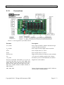
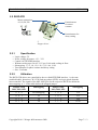
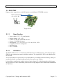
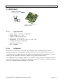
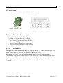
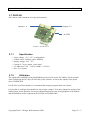
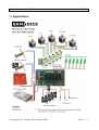
User's Guide for the BAM Shield with DICE boards
12. Nov. 2014
User Manual
BAM-Shield with DICE-Boards
Version: 1.0en
Author: Konrad Meyer
Date: 12. Nov. 2014
Page 1 / 13
User's Guide for the BAM shield
12. Nov. 2014
Index
1 Important notes.................................................................................................................................3
1.1 Warning notices........................................................................................................................3
1.2 General precautions..................................................................................................................4
1.3 Additional notes........................................................................................................................4
2 Components......................................................................................................................................5
2.1 BAM shield...............................................................................................................................5
2.1.1 Specification......................................................................................................................5
2.1.2 Connections.......................................................................................................................6
2.2 DICE-STK................................................................................................................................7
2.2.1 Specification......................................................................................................................7
2.2.2 Utilization..........................................................................................................................7
2.3 DICE-TMC...............................................................................................................................8
2.3.1 Specification......................................................................................................................8
2.3.2 Utilization..........................................................................................................................8
2.4 DICE-L6470.............................................................................................................................9
2.4.1 Specification......................................................................................................................9
2.4.2 Utilization..........................................................................................................................9
2.5 DICE-9555..............................................................................................................................10
2.5.1 Specification....................................................................................................................10
2.5.2 Utilization........................................................................................................................10
2.6 DICE-TC.................................................................................................................................11
2.6.1 Specification....................................................................................................................11
2.6.2 Utilization........................................................................................................................11
2.7 DICE-VN................................................................................................................................12
2.7.1 Specification....................................................................................................................12
2.7.2 Utilization........................................................................................................................12
3 Applications....................................................................................................................................13
History
Version
V1.0en
Description
First English version
Copyright 2014 © Wenger & Krautwasser GbR
Author
K. Meyer
Date
12.11.2014
Page 2 / 13
User's Guide for the BAM shield
12. Nov. 2014
Congratulations on your purchase of the universal BAM Shield from 2PRINTBETA. Please read the
instructions carefully before setting the device in operation. Please also take note of the general
safety instructions.
1 Important notes
Please observe all instructions given in this manual and read this information carefully before using
the product.
1.1 Warning notices
Safety (Warning / Caution)
•
Any operating conditions, such as use in hazardous areas, use in safety-related systems and
areas in which the loss of function may present a particular risk to life and limb are
prohibited with this product.
•
Do not place any objects around the device, which prevent a dissipation of heat.
•
Do not place flammable materials and substances in the environment of the device.
•
Take care that no metal objects touch the electronics when using the product.
•
Use for all interfaces matching plugs and wires.
•
Use only components that are within the given specifications.
•
Do not expose the device to liquids or corrosive substances.
•
Operate the unit in a clean, dry and dust free environment.
•
Should the structure be contaminated, disconnect the unit from the mains (remove the
power plug and disconnect the PCB from the power supply) and gently clean it.
•
Never let the appliance run unattended.
•
This kit is designed for self assembly and construction. The finished device can generate
and radiate high-frequency signals. The operation of the product may impair or interfere
with other electronic devices during operation depending on the type of setup. You are
hereby expressly advised of this risk and you should take the necessary measures to prevent
this types of interference. Each completed unit must be tested for long-term operation to
comply with applicable regulatory limits.
•
The responsibility for the security of a constructed machine lies at the builder and operator
of the system.
Copyright 2014 © Wenger & Krautwasser GbR
Page 3 / 13
User's Guide for the BAM shield
12. Nov. 2014
1.2 General precautions
General operating conditions:
•
Operate the device only in the final build up of the proposed hardware and with sufficient
cooling.
•
This device is sensitive to mechanical and physical influences.
•
Turn off the power supply and remove the mains plug before making any changes to the
installation and wiring of the setup. Not to do so may destroy your electronics and attached
equipment.
•
The device may be used only for the intended purpose within the limits of the electrical
specification.
1.3 Additional notes
Protection against electrostatic discharges
The unit is equipped with electronic components that can easily be destroyed by
electrostatic discharges. Use the usual measures to protect the components when
you install or use the device.
Not suitable for children
The device is not suitable for toddlers and children. Make sure that small parts and
accessories are kept safe and that the unit is protected against contact when
children may be present in the vicinity of the device. Also make sure that your
required tools are not in the reach of children and infants.
Recycling and re-use
The product contains substances which must not be disposed in household waste
(European directive 2002/96/EG). Please give this product to a designated location.
Improper handling of components whose components consist of potentially
dangerous or harmful substances can cause damage to the environment and can
endanger humans, animals and plants. Dispose this product properly and contribute
to the effective usage of natural resources. Your dealer will certainly help you. You
can also return the device to an authorized collection site for recycling electrical
waste and electronic equipment. For information about waste recycling, please
contact your city office, the public waste companies or an authorized site for the
disposal of electrical and electronic equipment.
Copyright 2014 © Wenger & Krautwasser GbR
Page 4 / 13
User's Guide for the BAM shield
12. Nov. 2014
2 Components
The kit of BAM&DICE includes the BAM shield and additional DICE boards for the individual
user dependent applications. For software examples for each module and complete firmwares in
specialized setups please visit www.2printbeta.de.
2.1 BAM shield
Picture 1: BAM shield with Arduino, without other components
2.1.1
Specification
• Input 1:
•
•
•
•
•
•
•
•
•
•
Imax = 15A*
12V-Variante: +8V .. 18V (without DC/DC converter)
24V-Variante: +16V .. 32V (with DC/DC converter)
Input 2:
Imax = 10A*
+8V .. 32V
Logic voltage: +5V
Interface for Arduino Mega 1280 and 2560
Configurable slots with jumpers
3 high current switches with up to 10A
Power connection over screw termination blocks
Diverse connections for expansions
Over-current fuses with 10A and 15A
Everything open source. Schematics, layout and firmware available
Five DICE board connectors for individual controller extensions
The board is not reverse polarity protected. Always pay attention to the correct polarity!
(*) The fuses can also be switched in case of heavy loads at high current switch D8.
When inserting and wiring equipment to the board, be sure that the power supply is switched off.
Copyright 2014 © Wenger & Krautwasser GbR
Page 5 / 13
User's Guide for the BAM shield
2.1.2
12. Nov. 2014
Connections
Picture 2: Pin assignment of the BAM shield
Pin name
Description
VIN1, GND
Power input for DICEs, Arduino and loads at high
current switches D9 and D10
VIN2, GND
Power input for load at high current switch D8
Vout1
Power output from VIN1, fused
Vout2
Power output from VIN2, fused
D10, D9, D8
High current switches for loads (low side switched)
Vcc
+5V power rail (Arduino generates this voltage)
+5V_EXT
External 5V power rail for additional servomotors
D12, D11, D6,D5,D4, TXD, RXD, A3, A4, A5,A9,
A10, D40, D44, D42, A12, A11, SCK, MISO, D53,
MOSI, D49, D32, D47, D45, D43, D41, D39, D37,
D35, D33, D31, D29, D27, D25, D23, D17, D16,
SDA, SCL, X-MIN, X-MAX, Y-MIN, Y-MAX, ZMIN, Z-MAX
Digital I/Os of the Arduino
MS3, MS2, MS1
Jumper for microstepping settings and I²C addresses
(for each DICE slot individually)
Copyright 2014 © Wenger & Krautwasser GbR
Page 6 / 13
User's Guide for the BAM shield
12. Nov. 2014
2.2 DICE-STK
Motor connections
A1,A2, B1, B2
Potentiometer
for motor
currents
Potentiometer for
decay setting
Picture 3: DICE-STK
Stepper driver
2.2.1
•
•
•
•
•
•
•
Specification
Logic voltage: 5V
Power voltage for motor: +9V .. 32V
Control via STEP/DIR interface
Without cooling up to 2A (65°C). Up to 2.86A with cooling air flow.
Substepping: 1, 1/2, 1/4, 1/8, 1/16, 1/32, 1/64, 1/128
Two trimmers for phase currents and decay setting
Size: 51x43mm
2.2.2
Utilization
The DICE-STK drivers are controlled by the so-called STEP/DIR interface, i.e. the state
(enable/disable), direction (CW, CCW) and step pulses (STEP) are logic signals from the
microcontroller. The signals of the MS1..MS3 pins for the respective DICE slot define the
microstepping. A ' 1 ' in the table defines the plugged jumper.
Jumper setup
MS3, MS2, MS1
Substepping
Jumper setup
MS3, MS2, MS1
Substepping
0
0
0
No substepping
1
0
0
1/16
0
0
1
1/2
1
0
1
1/32
0
1
0
1/4
1
1
0
1/64
0
1
1
1/8
1
1
1
1/128
Copyright 2014 © Wenger & Krautwasser GbR
Page 7 / 13
User's Guide for the BAM shield
12. Nov. 2014
2.3 DICE-TMC
High precision stepper driver with SPI interface and additional STEP/DIR interface.
Motor connections
A2, A1, B1, B2
Picture 4: DICE-TMC
Stepper driver
2.3.1
•
•
•
•
•
•
•
•
2.3.2
Specification
Logic voltage: 3,3V / 5V (configurable)
Supply voltage: +9V .. 30V
Control via SPI and STEP/DIR interface
Current: 2.6A RMS (4A max.)
Substepping: 1, 1/2, 1/4, 1/8, 1/16, 1/32, 1/64, 1/128, 1/256
Completely software configurable
Stall detection
Size: 51x44mm
Utilization
The DICE-TMC drivers are controlled by SPI and feature an additional step- and a direction input
(DIR) for the synchronous control with other modules. The signals MS1..MS3 on the BAM shield
are not used.
To use the module in a special setup we recommend the pre-configured Arduino library, which you
can download with an example program for the first steps on our website.
It is possible to configure the module to lower logic voltages. To do this change the solder jumper
on the topside. For more information please use the wiring diagram of the module and the datasheet
of TMC2660.
Copyright 2014 © Wenger & Krautwasser GbR
Page 8 / 13
User's Guide for the BAM shield
12. Nov. 2014
2.4 DICE-L6470
Motor connections
B1, B2, A2, A1
Picture 5: DICE-L6470
Stepper driver
2.4.1
•
•
•
•
•
•
•
•
2.4.2
Specification
Logic voltage: +3.3V/ 5V (configurable)
Supply voltage: +9V .. 35V
Control via SPI and STEP input
Up to 3ARMS. Up to 7A max.
Substepping: 1, 1/2, 1/4, 1/8, 1/16, 1/32, 1/64, 1/128
Completely software configurable
Sensorless stall detection
Size: 51x44mm
Utilization
The DICE-L6470 drivers are controlled via the SPI and offers an additional step input for
synchronous operation. The signals of the MS1..MS3 pins from the BAM shield are not used.
For utilization we recommend to setup the module with an appropriate Arduino library. On your
website you can download it and also a suitable code example for the first steps.
The configuration to lower logic voltages is also possible. For this you have to change the solder
jumper on the backside to 3V3 and place a jumper on resistor R7. For further information please
refer to the schematics and the datasheet of L6470PD.
Copyright 2014 © Wenger & Krautwasser GbR
Page 9 / 13
User's Guide for the BAM shield
12. Nov. 2014
2.5 DICE-9555
IO port expander with 16 digital signal lines and power output
Picture 6: DICE-9555
2.5.1
•
•
•
•
•
•
•
2.5.2
Picture 7: DICE-9555 connection
Specification
Logic voltage:: +5V, +3V3 (configurable)
Control via I2C-interface (max. 400kHz)
Up to 50mA per pin and 200mA overall current
16 configurable I/O pins
Interrupt signal for detection of signal changes
Short circuit protected output voltage (200mA)
Size: 51x31mm
Utilization
The signals MS1..MS3 on the BAM shield are used to define the I2C address of the module. The
usable address range lies between 32d (100000b) and 39d (100111b).
With the first use of this module we recommend the example program from our website.
It is possible to configure the module to lower logic voltages. To do this, change the solder jumper
on the topside.
For more information please use the wiring diagram of the module and the datasheet of
PCA9555PW.
Copyright 2014 © Wenger & Krautwasser GbR
Page 10 / 13
User's Guide for the BAM shield
12. Nov. 2014
2.6 DICE-TC
Temperature measurement unit for three thermocouples (K type) with SPI interface
Thermocouple
input 1
Thermocouple
input 2
Thermocouple
input 3
Picture 8: DICE-TC
2.6.1
•
•
•
•
•
•
2.6.2
Specification
Logic voltage: +5V, +3V3 (configurable)
Control via SPI
3 channels for thermocouples
Measurement range: -200°C to 700°C (-328°F to 1292°F)
Automatic error detection (short, no sensor)
Size: 51x44mm
Utilization
The signals MS1..MS3 on the BAM shield are not used by this module.
For the reading of each temperature value, the chip select signal of the corresponding channel must
be enabled by the corresponding GPIOs. You can find an example and a suitable Arduino library
for this module on our website on the product page.
It is possible to configure the board for lower logic voltages. To do this, remove the Zero-Ohm
resistor from R3 and place it (or a jumper) on R2.
For more information please use the wiring diagram of the module and the datasheet MAX31855.
Copyright 2014 © Wenger & Krautwasser GbR
Page 11 / 13
User's Guide for the BAM shield
12. Nov. 2014
2.7 DICE-VN
Valve driver with 8 channels for relays and actuators
Outputs 1..4
Outputs 5..8
4x GND
Picture 9: DICE-VN
2.7.1
•
•
•
•
•
•
2.7.2
Specification
Logic voltage: +5V, +3V3 (configurable)
Control via I2C interface (max. 400kHz)
Supply voltage: 10,5 - 35V
Current: 0,7 A per output (4A in sum)
I²C addresses: 112d .. 115d (111000b .. 111011b)
Size: 51 x 44 mm
Utilization
The signals MS1 and MS3 on the BAM-Shield can be used to set the I2C address for the module.
After configuring the I2C chip (PCA9538A) in the software, it can set the outputs of the power
driver VN808CM-E.
For the first use of this module we recommend the example program from our website.
It is possible to configure this module for lower logic voltages. To do this, change the setting of the
solder jumper on the backside. For more information please use the wiring diagram of the module
and the datasheets of the components PCA9538A and VN808CM-E.
Copyright 2014 © Wenger & Krautwasser GbR
Page 12 / 13
User's Guide for the BAM shield
12. Nov. 2014
3 Applications
Picture 10: Wiring diagram of BAM&DICE in a 3D printer with the DICE-STK drivers
Copyright 2014 © Wenger & Krautwasser GbR
Page 13 / 13