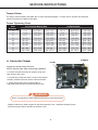
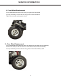
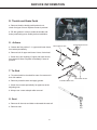
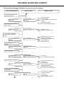
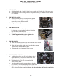
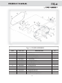
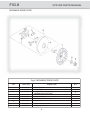
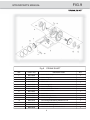
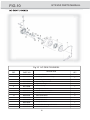
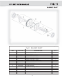
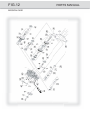
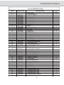
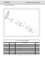
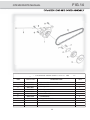
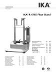
1
A Better Built Machine.
Owner’s Manual
Parts Manual
READ THIS MANUAL CAREFULLY,
IT CONTAINS IMPORTANT SAFETY INFORMATION.
INTERCEPTOR GTR 250
MODEL:2861-Live Axle
This kart is designed for off-road use only
and does not comply with Federal Motor Vehicle Safety Standards.
Recommended for Ages 16+
C-GTR-2861-LIVE AXLE-003-03-2007
FOREWORD
Thank you for purchasing our kart. We hope you will enjoy it. Before you begin operating the kart,
please carefully read this Owner’s Manual for the Interceptor GTR 250, as it contains important
safety and maintenance information. Failure to follow the warnings contained in this manual could
result in serious injury or death.
The Interceptor GTR 250 fits the needs of a wide variety of kart users above 16 years old.
Beginners should seek instruction from your dealer or qualified instructors before and during
intial use of the kart. We also recommend that you practice in a large open area until you become
familiar with operations of this kart.
Be sure to follow the recommended maintenance schedule and service your kart accordingly.
Preventive maintenance is extremely important to the longevity of you kart. Those who will be
servicing this kart should carefullly review this manual before performing any repair or services.
All information, illustrations photographs, and specifications contained in this manual are based on
the latest product information, available at the time of publication. Due to improvements, or other
changes, there may be some discrepancies in this manual. Therefore, if newer information is
needed in the future, please contact the local distributor.
Distributor reserves the right to make production changes at any time, without notice, and without
incurring any obligation to make same or similar changes to vehicles previously built or sold.
We hope you will have a pleasant experience with our product. Thanks again for choosing our
kart.
Carter Brothers Manufacturing, Co. , Inc.
1871 U.S. Highway 231 South
Brundidge, Alabama 36010
Phone: 800-523-5278
INDEX
Owner’s Manual
Warranty
1
About Safety
5
Important Safety Information
6
Safety Labels
8
Are You Ready To Drive?
9
Is Your Vehicle Ready To Drive?
11
Safe Driving Precautions
13
General Informations
15
Specifications
16
Locations Of Parts
18
Operation
20
Periodical Checks And Services
25
Service Instructions
26
Service Information
31
Wiring Diagram
40
Trouble Shooting Charts
Set-up Instructions
41
46
Parts Manual
Head Cover
Fig.1
Cylinder Head Comp
Fig.2
Cylinder Assembly
Fig.3
L Cover Assembly
Fig.4
L Crank Case
Fig.5
R Crank Case
Fig.6
R Case Cover
Fig.7
Movable Drive Face
Fig.8
Crank Shaft
Fig.9
AC Gen Flywheel
Fig.10
Balance Shaft
Fig.11
Mission Case
Fig.12
Oil Pump Assembly
Fig.13
Cylinder Head Side Cover Assembly
Fig.14
Driven Pully Set
Fig.15
A.I.C.V.Assembly
Fig.16
Carburetor Assembly
Fig.17
Frame Group
Fig.18
Steering Shaft Assembly
Fig.19
Suspension Arm Assembly
Fig.20
Rear Cargo Rack/Seat/Belt
Fig.21
Engine/Muffler/Air Cleaner
Fig.22
Rear Swing Arm
Fig.23
Rear Housing
Fig.24
Wire Harness/Electrical
Fig.25
Trail Board
Fig.26
Tool Kit
Fig.27
Warning Stickers
Fig.28
Stickers
Fig.29
INDEX
Services Manual
General Information
1.1
Service Maintenance Information
2.1
Lubrication System
3.1
Fuel System
4.1
Cylinder Head / Valve
5.1
Cylinder / Pistion
6.1
“V” Type Belt Driving System / Kick-Starter
7.1
Final Driving Mechanism
8.1
Alternator
9.1
Crankshaft / Crankcase
10.1
Cooling System
11.1
Electrical Equipment
12.1
WARRANTY
A Better Built Machine.
CARTER KARTS LIMITED WARRANTY
REGISTRATION
ALL UNITS MUST BE REGISTERED WITHIN 10 DAYS OF PURCHASE OR THE WARRANTY IS VOID
To register your product, complete the Warranty Registration form. Fax or mail the warranty
registration form with a copy of the sales receipt to Carter. A warranty registration form
MUST be on file with Carter before a warranty claim can be processed.
WARRANTY PERIOD
The warranty period starts from the date that the unit is sold to the first retail purchaser for all
Carter products During the warranty coverage period, we will cover warranty parts and labor only.
Parts repaired and replaced under this warranty are covered only for the remainder of
the kart’s warranty.
WARRATNY PERIODS FOR ALL KARTS ARE AS FOLLOWS:
FRAME FOR 1YEAR
Void if frame is broken or bent due to abuse.
1. Underside scraped abusively.
2. Wheels are bent or broken due to impact.
3. Spindles are bent due to impact.
4. Paint is worn off of rear bumper, indicating an extra rider.
5. Axles are bent out of ordinary position either horizontally or vertically.
6. Non-factory altering of engine or frame and it’s components.
If the frame is found to be defective due to material and/or workmanship when
inspected at an authorized Carter Service Center. Carter will at its option - repair
or replace defective parts to the original purchaser at no charge.
INTERCEPTOR GTR 250 2R PARTS COVERAGE
Warranty starts from the date of purchase by the first retail purchaser.
—> Engine: 2 year Limited factory warranty. *
—> A-Arm, Spindles, Axles, Rack & Pinion: 90 days
—> Electronics, Carburetor & Muffler: 90 days
—> Battery : 30 days
---> Radiator: 90 days
---> CVT: 60 days
1
WARRANTY
* The second year of the engine warranty is for the FUNCTION of certain engine parts.
Function is described as warranty coverage for parts that are not normally exposed to misuse,
abuse, or extreme wear. These engine parts are warranted to be free of manufacturing flaws
such as stress cracks, inferior material (metal), casting flaws, and machining flaws. Upon
part failure, only Carter Brothers Manufacturing, Inc. may determine if it is covered. Any failure
or damage to a part that does not influence its function will not be covered. Normal wear of
these parts is not covered. Parts covered under the second year period would include, but not
necessarily be limited to:
Head cover
Cylinder, and Cylinder Head
Left Case Cover
Left Crankcase
Right Case Cover
Right Crankcase
Mission Case
Cylinder Head Side Cover
Certain Internal Engine Parts
Certain Bearings and Gears
PARTS NOT COVERED
This warranty does not cover consumable wear and tear items such as, but not limited to:
Brake pads
Throttle cable
Tires
Brake cable
Oil changes
Chains
Problem occurring due lack of proper maintenance
Seats
Problem occurring due to abuse
Fasteners
Air Filters
Modifications to your GTR 250 that are not Carter approved will void the warranty.
Defective parts are subject to recall by Carter upon failure, and are required to
be held by the dealer or service center until the warranty claim is settled.
WARRANTY COVERAGE
Carter Brothers Manufacturing, Inc. will repair or replace, at its option, any part that is found
defective in material or factory workmanship under normal use.
Parts used in the “repair or replace” process under this warranty are covered only for the
remainder of the GTR warranty.
TO QUALIFY FOR THIS WARRANTY:
The GTR must be purchased from a dealer who is an authorized Carter dealer, and
Prior to delivery to the purchaser, set-up and pre-delivery service must be performed
by a dealer who is an authorized Carter dealer.
All units must be registered WITHIN 10 DAYS OF PURCHASE or the warranty is void.
All warranty work must be performed by an authorized Carter dealer or service center.
2
WARRANTY
OWNER’S WARRANTY RESPONSIBILITIES
As the kart owner, you are responsible for presenting your kart to the dealer or service centre
as soon as a problem exists.
All shipping and transportation charges for any items returned for warranty evaluation
and/or replacement are to be provided by the kart owner. Costs from kart owner to dealer
or service center are the kart owner’s responsibility.
IMPORTANT NOTICE:
We do not charge for parts for authorized warranty repairs. Any defective parts from
repairs are required to be returned to Carter upon request. All warranties are voided if the
vehicle has been altered for use in racing or competition, rented, used under abnormal
conditions, or subject to abuse, misuse, neglect or improper maintenance. Carter
in not liable for any damage claim or liability claim, personal or otherwise, resulting
from operation of this vehicle in any way. Carter reserves the right to change product
specifications, designs, and standard equipment without notice and without incurring
obligation. These vehicles are not designed or manufactured for racing or use on rental
tracks, public streets, public roads, highways, paved surfacesor right-of-ways.Always
wear an approved helmet and eye protection when riding. Always secure loose clothing
and long hair. Always wear seatbelts. Read the operations manual.
3
A Better Built Machine.
CUSTOMER SAFETY INFORMATION AND WARRANTY REGISTRATION FORM
INTERCEPTOR GTR 250
Warranty registration must be filed with Carter Brothers Manufacturing within 10 days of purchase or warranty will be void.
In order to validate the warranty, purchaser agrees and promises to hold Carter Brothers Manufacturing and the Dealer harmless
and indemnify them from all claims and demands or causes of action which may arise or be asserted against them arising or
allegedly arising from any claim related to the delivery of the Vehicle or its use by the Purchaser or any third parties, including
all attorney fees and legal costs whether or not any claim or assertion is deemed or found to be valid or not. All parties agree
and stipulate that any legal proceedings, which relate to or arise out of this transaction, shall be brought only in afederal or
state court located in the County of Pike,State of Alabama.
This form and Owner’s Manual contains vital safety information. Carter Brothers Manufacturing asks that you review the
warnings and verify that you have read and understood each warning by placing your initials on the line beside it.
I understand that I must: (please initial beside each number)
_____1.Always read the Owner’s Manual carefully, follow the operating procedures described in the Owner’s Manual
and pay special attention to the warnings contained in the manual and on all labels.
_____2.It Is Recommended that no one under the age of 16 operate the Vehicle.
_____3.Never allow any operation of the Vehicle beforer eading the Owner’sManual.
_____4.Never allow more than one operator and one passenger to ride on the Vehicle.
_____5.Never operate the Vehicle after consuming alcohol or drugs.
_____6.Never operate the Vehicle without wearing your seat belt ( Karts only ), a proper helmet, eye protection,
and protective clothing.
_____7.Never operate the Vehicle on unsafe terrain or at excessive speeds.
_____8.Never do wheelies, jumps or other stunts.
_____9.Never allow anyone to ride on the back or the front of the Kart or the handlebars of the Scooter.
_____10.Never allow the Kart to be driven on a public road of any kind, even a dirt or gravel one because you may
not be able to avoid colliding with other vehicles. Operating your Kart on a public road may be against the law.
_____11.Never operate the Kart on pavement. The Kart is not designed to be used on paved surfaces and may be
difficult to control.
_____12.Always follow the break-in period as described in the Owner’s Manual or your engine warranty will be voided.
_____13.Always clean the air filter as described in the Owner’s Manual or your engine warranty will be voided.
_____14.Never operate the Kart without wearing a proper helmet, eye protection, and protective clothing.
_____15.Never operate the Kart at night. The attached lights are for ornamental purposes only. They will not
provide sufficient lighting for night time operation.
In signing this document, the Purchaser acknowledges and agrees that he has read the Owner’s Manual and that failure to do
so voids all warranties, both implied and expressed.
I certify that I understand all of the above warnings, warnings in the Owner
’
s Manual, and that
failure to obey these warnings could result in death or severe injury.
.
Date of Purchase(mm/dd/yy)
First Name
Model Number
MI
VIN Number
Last Name
e-mail
Street Address
City
Zip Code
State
Website Address
Dealer Name
City
Home Telephone Number
Zip Code
State
Purchaser Signature
Please fill out this form and fax or mail it back to:Carter Brothers Manufacturing
y
W
w.carterbro.com
C-A-WR-03-2007
4
ABOUT SAFETY
In order to keep everyone safe, you must take responsibility for the safe operation
of your kart.
To help you make informed decisions about safety, we have provided operating
procedures and other information on labels and in this manual. This information
alerts you to potential hazards that could hurt you or others.
It is not practical or possible to warn you about all the hazards associated with
operating or maintaining a kart. You must use your own good judgment.
You will find important safety information in a variety of forms, including:
Safety Labels _ On the kart.
Safety Messages _ Preceded by a safety alert symbol
and one of two signal
words: WARNING, or CAUTION.
These signal word mean:
WARNING
Physical harm may result from failure to adhere to the instructions that are described
within the WARNING labels.
Safety Headings — such as important safety reminders or important safety precautions.
Safety Section — such as kart safety.
Instructions — how to use this kart correctly and safely.
This entire manual is filled with important safety information—please read it carefully.
5
IMPORTANT SAFETY INFORMATION
Your kart will provide you with many years of service and pleasure, providing
you take responsibility for your own safety and understand the challenges you may
meet while driving.
There is much that you can do to protect yourself while operating your kart. You'll
find many helpful recommendations throughout this manual. The following are a
few that we consider most important.
Follow the Age Recommendation
Experienced adult supervision should be present for all inexperienced operators.
Always Wear a Helmet
It's a proven fact: wearing helmets significantly reduces the number and severity of head
injuries. Always wear an approved motorcycle helmet. We also recommend that you
wear eye protection, sturdy boots, gloves, and other protective gear.
Drive Off-Road Only
Your kart is designed and manufactured for off-road use only. Its tires are not
made for pavement, and the kart does not have features required for use on public roads.
If you need to cross a paved or public road, shut the kart’s power off, get off and walk
your kart across.
Take Time to Learn & Practice
Even if you have driven other karts, take time to become familiar with how this
kart works and handles. Practice in a safe area until you build your skills and get
accustomed to this kart's size and weight.
Because many accidents involve inexperienced or untrained drivers, we urge all drivers
to take a training course approved by the Go-Kart Safety Institute. Check with your dealer
for more information on training courses.
Be Alert for Off-Road Hazards
The terrain can present a variety of challenges when you drive off-road. Continually
"read" the terrain for unexpected turns, drop-offs, rocks, ruts, and other hazards. Always
keep your speed low enough to allow time to see and react to hazards.
6
IMPORTANT SAFETY INFORMATION
Drive within Your Limits
Pushing limits is another major cause of kart accidents. Never drive beyond your
personal abilities or faster than conditions warrant. Remember that alcohol, drugs, fatigue,
and inattention can significantly reduce your ability to make good judgments and drive
safely.
Alcohol, Drugs, and Driving
Alcohol, drugsand driving don't mix. Even one drink can reduce your ability to respond to
changing conditions, and your reaction time gets worse with every additional drink. So
don't drink and drive, and don't let your friends drink and drive either. Do not operate
this kart if you are taking any prescriptions.
Do Not Operate this Kart at Night
Lower visibility at night can greatly reduce a driver’s judgment. Driving at night is
dangerous and will increase the possibility of an accident.
Never Run Your Kart Indoors
The exhaust from the engine contains carbon monoxide, a poisonous gas which is tasteless
& odorless. Carbon monoxide kills.
Keep Away from Moving Parts of the Kart
Never place your hands or any other body part near any moving part of the kart. Failure
to adhere to this warning may cause physical harm to your body.
Skidding or Sliding
The terrain’s surface can be a major factor affecting turns. Skidding in a turn is more likely
to occur on slippery surfaces such as snow, ice, mud, and loose gravel. If you skid on ice, you
may lose all directional control. To avoid skidding on slippery terrain, keep your speed low
and drive carefully.
7
8
ARE YOU READY TO DRIVE ?
Before each drive, make sure you and your kart are both ready to drive. This section
discusses how to evaluate your driving readiness, what items you should check on your
kart, and adjustments to make for your comfort, convenience, or safety.
Before you drive your kart for the first time, we urge you to:
Read this owner's manual and the labels on your kart carefully.
Make sure you understand all the safety messages.
Know how to operate all the controls.
Have an experienced adult present if operator is not experienced in this kart.
Before each drive, be sure:
You wear your seat belt at all times while driving your kart.
You feel well and are in good physical and mental condition.
You are wearing an approved motorcycle helmet (with chin strap tightened securely), eye
protection, and other protective clothing.
You don't have any alcohol or drugs in your system.
Protective Apparel
For your safety, we strongly recommend that you always wear an approved motorcycle
helmet, eye protection, boots, gloves, long pants, and long-sleeved shirt or jacket, whenever
you drive. Although complete protection is not possible, wearing proper gear can reduce the
chance of injury when you drive.
The following suggestions will help you choose the proper driving gear.
Helmets and Eye Protection
Your helmet is your most important piece of driving gear because it offers the best protection
against head injuries. A helmet should fit your head comfortably and securely.
An open-face helmet offers some protection, but a full-face helmet offers more. Regardless of
the style, look for a DOT (Department of Transportation) sticker on any helmet you buy. Always
wear a face shield or goggles to protect your eyes and help your vision.
WARNING
Operating this go-kart without wearing an approved motorcycle helmet, eye protection,
and protective clothing could increase your chances of head and/or eye injury, and the
possibility of death in the event of a severe accident.
Always wear an approved motorcycle helmet that fits properly and wear eye protection
(goggles or face shield), gloves, boots, long-sleeved shirt or jacket and long pants.
9
ARE YOU READY TO DRIVE?
Additional Driving Gear
In addition to a helmet and eye protection, we also recommend:
Sturdy off-road motorcycle boots to help protect your feet, ankles, and lower legs.
Off-road motorcycle gloves to help protect your hands.
Driving pants with knee and hip pads, a driving jersey with padded elbows, and a chest/
shoulder protector.
Driver Training
Developing your driving skills is an ongoing process. Even if you have driven other karts,
before driving take time to become familiar with how this kart works and handles. Practice driving
the kart in a safe area to build your skills. Do not drive in rough terrain until you get accustomed
to the kart's controls, and feel comfortable with its size and weight.
WARNING
Operating this kart without your seat belt could cause you to be thrown
from the kart, causing serious injury or death.
Age Recommendation
It is strongly recommended that no one under the age of 16 be permitted to operate this go-kart.
WARNING
A child driving a kart that is not recommended because he/she could lose control
of the kart resulting in severe injury or death.
No Alcohol or Drugs
Alcohol, drugsand karts don't mix. Even a small amount of alcohol can impair your ability
while operating a kart. Consult your doctor to be sure it is safe to operate a vehicle after
taking medication.
WARNING
Operating this kart after consuming alcohol or drugs can seriously
affect your judgment, cause you to react more slowly, affect your balance
and perception, and could result in serious injury or death.
Never consume alcohol or drugs before or while operating this kart.
10
IS YOUR VEHICLE READY TO DRIVE?
Before each drive, it is important to inspect your kart and make sure any problems you find
are corrected. A pre-drive inspection is a must, not only for safety, but because having a
breakdown, or even a flat tire, can be a major inconvenience.
If your kart has overturned or has been involved in a collision, do not drive it until your
kart has been inspected by your dealer. There may be damages or other problems you cannot
see.
WARNING
Improperly maintaining this kart or failing to correct a problem before
driving may cause a crash in which you can be seriously hurt or killed.
Always perform a pre-drive inspection before every drive and correct any
problems.
Pre-drive Inspection
Check the following items beford you get on the kart:
Engine Oil
Check the level and add oil if needed. Check for leaks.
Fuel
Check the level and add fuel if needed. Also make sure the fuel fill cap is securely fastened.
Check for leaks.
Tires
Use a gauge to check the air pressure. Adjust if needed. Also look for signs of damage or
excessive wear.
Nuts & Bolts
Check the wheels to see that the axle nuts are tight. Use a wrench to make sure all
accessible nuts, bolts, and fasteners are tight.
Underbody & Exhaust System
Check for and remove any dirt, vegetation or other debris that could be a fire hazard or interfere
with the proper operation of the kart.
Air Cleaner Housing Drain Tube
Check for deposits in the drain tube. If necessary, clean the tube and check the air cleaner
housing.
11
IS YOUR VEHICLE READY TO DRIVE?
Leaks, Loose Parts
Walk around your kart and look for anything that appears unusual, such as a leak or
loose cable.
Lights
Make sure the headlights, brake light, and tail light are working properly.
Throttle
Check the freeplay and adjust if needed. Press the throttle to make sure it moves smoothly
without sticking, and snaps back automatically when it is released.
Brakes
Press the brake pedal several times, check for proper brake pedal freeplay. Make
sure there is no brake fluid leakage.
Engine Stop Button
While engine is running, press and hold the engine stop button for two seconds. Make
sure engine stops.
Steering Wheel
Check that the wheels turn properly as you turn the steering wheel.
Cable
Check all cable housings for wear. Check the fittings for looseness. Replace or tighten as
needed.
12
SAFE DRIVING PRECAUTIONS
Off-Road Use Only
Your kart and its tires are designed and manufactured for off-road use only, not for
pavement. Driving on pavement can affect handling and control. You should not drive your
kart on pavement.
WARNING
Operating this kart on paved surfaces may seriously affect handling and
control of the kart, and may cause the vehicle to go out of control.
Never operate the kart on any paved surfaces, including sidewalks,
driveways, parking lots and streets.
When driving off-road, also remember to always obey local off-road driving laws and
regulations. Obtain permission to drive on private property. Avoid posted areas and obey
"no trespassing" signs.
You should never drive your kart on public streets, roads or highways, even if they are not
paved. Drivers of street vehicles may have difficulty seeing and avoiding you, which could lead
to a collision. In many states it is illegal to operate karts on public streets, roads and highways.
WARNING
Operating this kart on public streets, roads or highways could cause a
collision with another vehicle.
Never operate this go-kart on any public streets, roads or highways,
whether dirt, gravel or pavement.
Keep Hands and Feet on Controls
When driving your kart, always keep both hands on the steering wheel and both feet
on the foot controls. Removing hands or feet away from the controls can result in loss of
balance and reduce your ability to react and control the kart.
WARNING
Removing hands from steering wheel or feet from foot controls during operation
can reduce your ability to control the kart or could cause you to lose your balance
and fall off the kart.
Always keep both hands on the steering wheel and both feet on the foot controls
of your kart during operation.
13
SAFE DRIVING PRECAUTIONS
Control Speed
Driving at excessive speeds increases the chance of an accident. In choosing a proper speed,
you need to consider the capability of your kart, the terrain, visibility and other operating
conditions, plus your own skills and experience.
WARNING
Operating this kart at excessive speeds increases your chances of
losing control of the kart, which can result in an accident.
Always drive at a speed that is proper for your kart, the terrain, visibility
and other operating conditions, and your experience.
Use Care on Unfamiliar or Rough Terrain
Before driving in a new area, always check the terrain thoroughly. Don't drive fast on unfamiliar
terrain or when visibility is limited (it's sometimes difficult to see obstructions like hidden rocks,
bumps, or holes in time to react.)
WARNING
Failure to use extra care when operating this kart on unfamiliar terrain
could result in the kart overturning or going out of control.
Go slowly and be extra careful when operating on unfamiliar terrain. Always
be alert to changing terrain conditions when operating the kart.
Never drive past the limit of visibility. Maintain a safe distance between your kart and other
off-road vehicles. Always exercise caution and use extra care on rough, slippery and loose terrain.
WARNING
Failure to use extra care when operating on excessively rough, slippery or
loose terrain could cause loss of traction or vehicle control, which could result
in an accident, including an overturn.
Do not operate on excessively rough, slippery, or loose terrain until you have
learned and practiced the skills necessary to control the kart on such
terrain. Always be especially cautious on these kinds of terrain.
Do Not Perform Stunts
You should always operate your kart in a safe and reasonable manner. When driving,
always keep all four wheels on the ground.
WARNING
Attempting wheelies, jumps, and other stunts increases the chance of an
accident, including an overturn.
Never attempt stunts, such as wheelies or jumps. Don't try to show off.
14
GENERAL INFORMATION
MODEL IDENTIFICATION
FRAME NUMBER
The frame number or VIN is stamped on the upper firewall of the frame behind the seat.
VIN NUMBER LOCATION
ENGINE NUMBER
The engine number is located on the lower
front left side of the engine case.
FUEL RECOMMENDATIONS
FUEL
Gasoline should be 92 octane or higher.
Unleaded gasoline is recommended.
Engine oil should be SAE 10W-30.
BREAK-IN PROCEDURE
For the first 2 hours of riding, do not exceed 2/3 throttle.
Vary Engine speed for the first 5 hours.
Never hold engine at full throttle for long periods of time.
VIN NUMBER LOCATION
15
SPECIFICATIONS
DIMENSIONS
Overall Length ---------------------------------------------------------------------------- 90 in. (2286mm)
Overall Width ---------------------------------------------------------------------------- 62 in. (15748mm)
Overall Height ----------------------------------------------------------------------------- 63 in. (1600mm)
Wheelbase ---------------------------------------------------------------------------------- 68 in. (1727mm)
Front Track ------------------------------------------------------------------------------ 47.1 in. (1060mm)
Rear Track ------------------------------------------------------------------------------- 39.4 in. (1000 mm)
Ground Clearance ------------------------------------------------------------------------- 5.1 in. (130mm)
ENGINE
Type -------------------------------------------------------------------------------------------------- 4-Stroke
Engine Capacity --------------------------------------------------------------------------------------- 250cc
Bore / Stroke --------------------------------------------------------------------------------- 71mm / 63mm
Displacement ----------------------------------------------------------------------------------------- 294.4cc
Corrected Compression Ratio ---------------------------------------------------------------------- 10.5:1
Carburetor ----------------------------------------------------------------------------------------------- 22mm
Output Power ------------------------------------------------------------------------------ 13.2kw/7000rpm
Maximum Torque -------------------------------------------------------------------------20.6Nm/5500rpm
Starting -------------------------------------------------------------------------------------------------- Electric
Ignition ----------------------------------------------------------------------------------------------------- C.D.I.
Lubrication ----------------------------------------------------------------------------------- Force & Splash
Transmission ------------------------------------------------------------------- Automatic (C.V.T system)
Spark Plug ------------------------------------------------------------------------------------------------ CR8E
Plug Gap --------------------------------------------------------------------------------------------------0.8mm
Fuel Type -------------------------------------------------------------------------------Above 92 (unleaded)
Engine Oil ---------------------------------------------------------------------------------------- SAE-10W/30
_
Idling Speed------------------------------------------------------------------------------------1700+100
rpm
CAPACITIES
Maximum Load------------------------------------------------------------------- 2 riders or 180kg/400lbs
Fuel Tank ----------------------------------------------------------------------------------------------15L/4Gal
Engine Oil ----------------------------------------------------------------------------------------------- 1200cc
Starting ----------------------------------------------------------------------------------------------------------5s
DŽ DŽ
Climbing ------------------------------------------------------------------------------------------------- 20 -25
Battery ------------------------------------------------------------------------------------------------ 12V 12Ah
Head Lights ------------------------------------------------------------------------------------12V 35W/35W
Tail Light -----------------------------------------------------------------------------------------12V 21W/5W
Gear Oil------------------------------------------------------------------------------------------SAE140/650cc
Towing ----------------------------------------------------------------------------------------------500 lbs max
16
CHASSIS
Front, Rear Brake ----------------------------------------------------------------------------- Hydraulic disc
Front Tire -----------------------------------------------------------------------------------------23x7-10 14psi
Rear Tire ------------------------------------------------------------------------------------------25x7-12 14ps
Front Suspension ---------------------------------------------------------------------------------Dual A-Arm
Rear Suspension ---------------------------------------------------------------------------------Dual A-Arm
Restraint System --------------------------------------------------------------------- Dual 4-point Harness
Final Drive Chain --------------------------------------------------------------------------------
520 x 66
WEIGHT
Net Weight -----------------------------------------------------------------------------------------372kgs/819lbs
*The specifications are subject to change without notice.
1
LOCATION OF PARTS
MIRROR
SEAT BELT
HEADLIGHTS
STEERING WHEEL
R.R. WHEEL
FR. WHEEL
REAR CARGO RACK
DRIVE CHAIN
TOW BALL
18
LOCATION OF PARTS
12V OUTLET
HORN
KEY SWITCH
HEADLIGHT SWITCH
BLINKER
ENGINE STOP BUTTON
REAR CARGO RACK
RADIATOR
ENGINE
FUEL TANK
19
OPERATION
A. Operation Controls
WARNING - Do not attempt to start or operate the engine until you are completely familiar
with the location and use of each control necessary to operate this vehicle. The operator must
know how to stop this machine before starting and driving it.
a. Throttle
The right foot pedal is the throttle that controls the kart speed. As the engine speed
increases above idle, the clutch automatically engages and moves the vehicle forward. To
disengage the clutch at any time, allow the throttle to return to the idle position.
WARNING
Each time prior to start the engine, check the throttle assembly to ensure
that when the pedal is pushed all the way forward the assembly is working
smoothly and returns to idle when released. Do not operate if pedal or engine throttle
linkage fail to return to idle. If unable to correct the problem through lubrication,
adjustment, or replacement of worn parts, contact your dealer for assistance.
b. Brake
The brake is located on the left side of the kart. Applying pressure to the
pedal draws the brake caliper around the brake pump at the rear wheel and slows or stops
the kart.
KEY SWITCH
ENGINE STOP BUTTON
c. Start engine.
Insert the key into key-switch, turn the
key clockwise, release the key when
the engine starts. Kart must be in neutral.
The engine will warm up within 5 minutes
if the engine is cold you will need to pull
the choke lever under the seat.
(Warning: Don’t crank starter more
than 5 seconds at one time).
e. Engine stop button.
IMPORTANT STOP BUTTON TEST
Before driving this vehicle, test the engine
BRAKE
THROTTLE
stop button to assure that it is operating properly. With the engine running, push and hold the
engine stop button for two seconds for the engine to shut down.
20
OPERATION
B. Pre-Drive Inspection
WARNING
Perform this pre-drive inspection everyday before driving vehicle. If not
performed, serious damage to the vehicle or personal injury may result.
a. Check engine oil level. Check for leaks, add oil if required.
b. Check fuel level. Add fuel as necessary and do not overfill. Check for leaks.
c. Check brakes. Depress the rear brake pedal several times, then check for proper brake
pedal freeplay. Make sure there is no brake fluid leakage. Adjust if necessary.
d. Check tires. Check tire condition and pressure. The pressure on both front and rear tires
is 14 psi, respectively.
e. Check drive chain. Check drive chain’s condition and tension. Lubricate if necessary.
f. Check throttle. Check for smooth operation. Assure throttle “snaps” back to idle.
g. Check engine stop button. Perform engine stop button test. Repair as necessary.
h. Check all nuts, bolts, and fasteners. Check wheels to see that all axle nuts and lug nuts are
tightened properly. Check and tighten as necessary all other fasteners to specified condition.
i.
Check occupant protection bar. Ensure all occupant protection bars are in place before
operating the kart.
j.
Check brake light. Check for proper operation.
k. Check wheels. Check for tightness of wheel nuts and axle nuts; check that axle nuts are
secured by cotter pins.
l.
Check steering. Check for free operation for any unusual looseness in any area.
WARNING
Always follow rules for safe operation and wear a helmet.
21
OPERATION
C. Passengers
The vehicle allows for two riders only. Combined
maximum weight of driver and the passenger should
not exceed 180kg or 400lbs.
D. Seat Adjustment
The seat must always be securely fastened in the
position which best affords the operator control of
the foot pedals, steering wheel, and the remote
stop button.
a. Pull seat adjustment handle upward to disengage
seat slide.
SEAT ADJUSTMENT HANDLE
b. Move seat to desired position.
c. Be sure seat adjustment handle snaps back into
place and that seat is locked into position.
WARNING
Before attempting to adjust the seat, ensure that kart engine is stopped.
WARNING
Never operate this kart when the provided seat is not securely fastened, to
do so could result in a strong possibility of severe personal injury or loss of life.
Before attempting to adjust the seat, ensure the kart engine is stopped.
E. Parking Brake Adjustment
a. Push forward the brake lever so that the unit can roll
freely. Pull back the lever to engage the parking brake.
b. When brake lever is in forward position, there
$'-867,1*187
5(9(56(&$%/(
needs to be 1/2” of freeplay. If the adjustment
is not correct, loosen lock nut #2, then adjust
lock nut #1 to the proper amount of freeplay.
$'-867,1*187
5(9(56(&$%/(
Always stop the kart before changing gears.
22
OPERATION
F. Gear Shift Lever
YOKE
YOKE ADJUSTMENT
a. Each end of the cable has a threaded yoke on it.
b. You must remove the pin or bolt in either end of
the cable to which the yoke is attatched.
c. To adjust an end, loosen the jam nut and turn the
yoke the appropriate way.
CABLE MOUNT
CABLE MOUNT ADJUSTMENT
a. The cable has a threaded stud and jam nuts on each
end that is used to attatch itself to the frame.
b. To adjust, loosen one jam nut on one or both ends
and adjust the appropriate direction.
c. Tighten jam nuts.
SHIFT LEVER ADJUSTMENT
SHIFT LEVER
a. On the rear end of the cable a shift lever is attatched to
both it and the engine.
b. The lever is on a splined shaft protruding from the engine.
c. Remove the bolt which holdV this lever to the engine.
d. Slide the lever off the shaft and turn the appropriate way,
one spline at a time.
e. Once in the appropriate position tighten all bolts back.
23
OPERATION
G. Starting And Operating Instructions
a. Before starting the engine, be sure that the driver is seated properly in the kart with the seat belt fastened.
b. Test the kart in an open space at the beginning to learn how to start, turn, and stop.
c. Operate the kart slowly until you are familiar with it.
d. The turning radius of this kart is small and agile, so the centrifugal force is very high when
turning at high speed. Slow down to a more controllable speed when turning to prevent the
kart from rolling over.
e. Always turn the vehicle at a slow, controllable speed to prevent the vehicle
from turning over. Keep your left foot ready to press the brake. If at any time the vehicle
feels unstable, reduce your speed.
24
PERIODICAL CHECK AND SERVICES
Have your kart checked, adjusted, and record maintenance performed.Have these services performed
periodically by your Carter Authorized Dealer to maintain the kart at the optimum condition.
Item
Air Cleaner
Fuel Filter
Engine Oil Change
Tire Pressure
Battery Inspection
Brake Check
Steering Check
Tightness of Screws
Frame Lubrication
Gear Oil Check
Gear Oil Change
Spark Plug
Exhaust Pipe
Ignition Timing
Emission
Throttle
Engine Bolt Tightening
CVT Driving Device (belt)
CVT Driving Device (roller)
Drive Chain
Lights/Electrical Equipment
Fuel Lines
Cam Chain
Valve Clearance
Lines/Cooling Connections
Coolant Reservoir
Coolant
Code:
Every
300km
180 mi
I
I
R
I
I
I
I
I
I
R
I
I
I
I
I
I
I/L
I
I
I
I
I
I
I
1 Month
3 Months 6 Months
1 Year
C
R
I
R
Replacement for every 1000 km/600 miles
I
I
I
I
I
L
I
Replacement for every 5000 km/3000 miles
I
R
I
I
I
I
I
I
R
C
I/L
C
I
I
I
I
I
I
I
R
I=Inspection, Cleaning and Adjustment
R= Replacement
C=Cleaning (replace if necessary)
L=Lubrication
The above maintenace schedule is established by taking the monthly 1000km/600 miles as a
reference, which ever comes first.
Clean or replace the air cleaner element more often when the kart is operated in a dusty
or polluted environment.
Maintenance should be performed more often if the kart is frequently operated at
high speeds and after the kart has accumulated higher mileage.
25
SE RVICE INSTRUCTIONS
Torque Values
The torque values listed in this table are for more important tightenHG torque values. Please see standard
values for torques not listed in the table.
Torque Tightening Chart
Bolt
Diameter
4
5
6
8
10
12
14
16
18
Conventional Mar ked Bolt
N.m
Kg.m
Ib-ft
1 ~2
0.1 ~0.2
0.7 ~1.5
1 ~4
0.2 ~0.4
1.5 ~3.0
4 ~7
0.4 ~0.7
3.0 ~5.0
10 ~16
1.0 ~1.6
7.0 ~11.5
22 ~35
2.2 ~3.5
16.0~25.5
35 ~50
3.5 ~5.5
25.5 ~40
50 ~80
5.0 ~8.0
36.5 ~58
80 ~130
8.0 ~13.0
58 ~94
130 ~190
13.0~19.0
94 ~137.5
N.m
1.5 ~3
3 ~6
8 ~12
18 ~28
40 ~60
70 ~100
110 ~160
170 ~250
200 ~280
8.8 Mar ked Bolt
Kg.m
Ib-ft
0.15 ~0.3
1.0 ~2.0
0.3 ~0.6
2.0 ~4.5
0.8~1.2
6.0 ~8.5
1.8 ~2.8
13.0 ~20.0
4.0 ~6.0
29.0 ~43.5
7.0 ~10.0
50.5 ~72.5
11.0 ~16.0
79.5 ~115.5
17.0 ~25.
123.0 ~181.0
20 ~28.0
144.5 ~202.5
ELEMENT
A. Service Air Cleaner
CLAMP
Service air cleaner every 20 hours.
NOTE: Service more often under dusty conditions.
a. Loosen 4 hooks from the air cleaner cover and
then remove the cover.
b. Loosen the clamp strip and 1 screw of air cleaner
element, and then remove the air cleaner element.
c. Clean the element with non-flammable or
high-flash point solvent and then squeeze it dry.
WARNING
Never use gasoline or acid organized solvent to clean the element.
Soap the element in clean engine oil and then squeeze it out. Install the element on the
element seat and then install the air cleaner cover.
26
SERVICE INSTRUCTIONS
B. Engine Lubrication
You must change the oil in the crankcase after the first 5 hours of operating your new
engine and after 10 hours of use thereafter. This will insure proper lubrication
of internal parts and prevent costly repairs due to excessive wear.
WARNING
Used oil must be disposed of at a proper collection center.
a. Remove drain plug located on the right rear side of engine.
Tip kart backwards slightly by blocking the front tires and
drain oil into suitable container.
b. Remove and clean oil screen.
c. Replace drain plug and tighten securely. Place kart in a level
position.
d. Refill crankcase (approximately 1200 cc or 1 1/4 quarts) to
top of filler neck with SAE 10W30 oil.
e. Check oil level before each use of kart or after each 10 hours
of operation. Add oil to bring up to proper level. Do not mix
various grades of oil.
ENGINE OIL PLUG COVER
C. Gear Oil Check and Change
JOIN BOLT
PP
a. Remove oil join bolt. Remove drain bolt and drain oil out.
b. Install the drain bolt after drained. Torque value: 1.1~1.5kgf-m
c. Make sure that the drain bolt washer can be re-used.
d. Add oil to specified quantity from the join hole.
Gear Oil Quantity: 650 cc when replacing.
e. Make sure that the join bolt washer can be re-used, and install
the bolt. Torque value: 3.5~4.5kgf-m
f. Start engine and run engine for 2-3 minutes. Turn off engine and
make sure that oil level is at correct level. Make sure that there is
no oil leakage.
Figure 8
DRAIN BOLT
27
SERVICE INSTRUCTIONS
D. Carburetor Adjustment
Never make unnecessary adjustments. The factory recommended settings are correct for most
applications.
WARNING
Air screw was set at factory, so no adjustment is needed. Note the number of
turns it takes to scew it all the way in for ease of installation. The parking brake
must be used to stop the kart to perform the adjustments.
THROTTLE VALVE STOPPER SCEW
a. Warm up engine (5~10min).
b. Tighten the air screw gently. Backout 2 turns.
c. Connect the tachometer, adjust the throttle to limit
the idle speed. The standard value is 1700 RPM.
d. Turn the air screw counter-clockwise slowly and
observe the RPM of the engine, stop adjusting as the
RPM reaches top speed.
e. Adjust the screw and adjust the idle speed to an
ideal value.
f. Recheck and readjust the idle speed if necessary.
AIR ADJUSTMENT SCREW
E. Spark Plug
a. Remove the spark plug and inspect it each time you
change the oil. (Use a spark plug wrench). Keep the
electrodes clean and free of carbon. The presence of
carbon or excess oil will gently reduce proper engine
performance. If possible, check the spark plug gap
(area between electrodes) using a wire feeler guage.
This specification is 0.8~0.9mm.
b. Before installing the spark plug, coat threads lightly
with graphite grease, if possible, to ensure easy removal
in the future.
c. It is advisable to replace the spark plug at least once a
year to insure easy starting and good engine performance.
28
clean dint or carbon
0.8~0.9mm
washer
proclean
SERVICE INSTRUCTIONS
F. Cleaning Instructions
Keep your kart clean. With clean rag, wipe off dirt and oil from around controls. Wipe off any
spilled fuel and oil. Keep the engine clean of foreign objects, and be sure to check that air
intake fan is free of debris for proper cooling.
G. Drive Chain
How to Tighten Chain:
a. On this unit in order to tighten the chain the entire
engine must be “slid” forward.
DRIVE CHAIN
b. Loosen the engine plate bolts (2 front and 2 rear).
REAR PLATE BOLTS
c. Loosen air box bolts (4 total).
d. Loosen muffler bolts (2 total).
e. Slide engine forward and tighten all bolts.
NOTE: When pushing the engine forward the front
engine mount will try and tilt forward. This will
cause the engine to return to its original position
once force is removed. You will need to tap the bottom
of the engine plate to keep it from tilting. Check gear
positions after adjusting chain.
How to Lubricate Chain:
FRONT PLATE BOLTS
AIR BOX BOLTS
Lubricate chain with a spray-on type chain lubricant
to increase the life of the chain.
MUFFLER BOLTS
29
SERVICE INSTRUCTIONS
H. Adjustment of Front and Rear Shocks
There are five adjustable positions on each shock. The default position is in the middle.
a.Use a round nut wrench to adjust the shock.
b.The tension of the shock spring will increase as
you scew to the right.
c. Adjust accordingly to the weight of the riders.
/()7 527$7(
5,*+7 527$7(
I. Front or Rear Shock Removal
a. You must first lift either the front or the rear of
the kart off the ground, depending on which shocks
you want to remove.
635,1* $'-8670(17 &$0
b. Once the kart is off the ground remove the bolt
from both top and bottom of each shock.
BOLT
BOLT
PP
BOLTS
BOLTS
BOLTS
Figure 8
REAR SHOCKS
FRONT SHOCKS
30
SERVICE INFORMATION
J. Front Wheel Replacement
Do not disassemble the castle nuts when you replace the front wheels.
It is only necessary to remove the four 4 lug nuts to remove the wheel.
Tighten the nuts after replacing the wheels.
(1*,1( 2,/ 3/8* &29(5
5,*+7 527$7(
Figure
Figure711
K. Rear Wheel Replacement
Do not disassemble the castle nuts when you replace the rear wheel and hub assembly.
Remove the cotter pin and the 24mm nut. Then slide off wheel and hub assembly.
It is only necessary to remove the four 4 lug nuts to remove the wheel by itself.
PP
Figure 8
31
SERVICE INFORMATION
L. Front Wheel Alignment
a. The front wheels should be “toe-in” from 1/8” to 1/4”. To check for alignment, measure
distance A and B between the centerline (CL) of the wheels. The proper toe-in dimension A
should be 1/8” – 1/4” greater than dimension B.
b. To adjust the alignments, loosen the lock nuts on both sides of Front Tie Rods. To make
Dimension B smaller, turn the rod to the left. Adjust the rod to the right direction to make
Dimension B larger. After adjusting to the desired length, tighten the lock nut against the rod end.
Recheck the dimensions for proper alignment.
A
LOOK NUT, FR.
WHEEL TIE ROD
CL
CL
LEFT ROTATE
RIGHT ROTATE
RIGHT ROTATE
LEFT ROTATE
FRONT WHEEL TIE ROD
B
32
SERVICE INFORMATION
M. Fuel Switch (Petcock)
This vehicle has a manually operated fuel SHWFRFN with three positions. Please follow maintenance
procedures accordingly.
a. Periodically clean the petcock externally with grease remover and water.
b. Check for any leaks or seeping fuel.
“ON” Position
The normal operating position for the fuel valve lever is the “ON” position. In this position, fuel
will flow to the carburetor.
“RES” Position5HVHUYH
If the fuel level in the fuel tank becomes too low for the engine to operate with the fuel valve lever
in the “ON” position, turn the lever to the “RES” position to use the reserve fuel supply, and refuel
as soon as possible.
“OFF” Position
The closing position for the fuel valve is the “OFF” position. When the vehicle is not in use, always
make sure the petcock is in the “OFF” position.
N. Chassis
Grease chassis bushings and bearings with grease every six-months to assure smooth operation
and extended life of the bushings and the components. If used in extreme wet, muddy,
or dusty conditions, greasing is recommended more often.
33
SERVICE INFORMATION
O. Steering Shaft
a. Remove WKH nutsIURPsteering block *rease inside of steer-block periodically.
Nut
Steering Column
b. Loosen steering shaft, clamp nut and steering gear box.
Steering Shaft Link
Steering Gear Box
Clamp Nut
c. Remove steering shaft.
Steering Shaft
34
Needle Bearing
SERVICE INFORMATION
P. Steering Gear Box and Ball
HEAD AND STEERING GEAR BOX
a. Remove four bolts on LH and RH clamp nut
and steering gear box.
b. Remove and check ball head dust cover and
steering gear box for wear.
Ball Head Dust Cover
Bolts and Nuts
Steering Gear Box
c. Check steering cover on sides of steering gear box and grease the ball head.
Ball Head
d. Fill steering gear box with grease after cleaning the dust. Replace the ball joint if it is loose or not
smooth.
Steering Knuckle Support
Ball Joint
35
SERVICE INFORMATION
Q. Steering Knuckle Support
a. Remove rubber dust cover of the knuckle support.
Ball Head Dust Cover
b. Check the grease of ball joint. Clean it if it is dirty and fill with grease.
Filled With Grease
c. Replace the steering knuckle support if the ball joint is loose or steering isn’t flexible.
Steering Knuckle Support
Ball Joint
36
SERVICE INFORMATION
R. Throttle and Brake Pedal
a. Remove throttle, throttle pedal and axle nut,
check for signs of wear. Replace if wear is present.
b. Fill with grease in order to make the throttle and
brake pedal swing more flexibly before installation.
S. A-Arms
a. Grease the flex points of WKH upper and lower A-arm,
front wheel periodically.
Rear upper A-arm
Frontal upper A-arm
b. Remove bolt of upper and lower A-arm, front wheel.
c. Check the nylon bushing of upper and lower A-arm,
front wheel for wear. Replace immediately if wear is
present.
T. Tie Rod
a. Tie rods should be checked for ease of movement in
their full rotation.
Rear lower A-arm
Frontal lower A-arm
b. Remove protective boot and apply grease.
c. Check tie rod ends periodically for tightness at the
adjusting nuts.
d. Always use a new cotterpin after removal.
U. Seat
a. Remove all the nuts and bolts underneath the seat rail.
b. Remove seat.
37
SERVICE INFORMATION
V. Radiator
WARNING
While engine is running, never attempt to open the radiator filler cap. The pressurixed
hot coolant may shoot out and cause serious scalding injury. No maintenance work is
allowed to be performed unless the engine is completely cooled down.
a. Refill the radiator with distilled water or specified
additives.
b. Add coolant to the reservoir.
c. The cooling system can be serviced on the kart.
d. Never spill the coolant on the painted surface.
e. Test the cooling system for any leakage after the
repair.
W. Storage Instructions
WARNING
Do not drain fuel while engine is hot. Be sure to move kart outside before draining fuel.
In the event that your kart is not to be operated for a period exceeding 30 days or at the end
of each driving season, prepare for storage as follows:
a. Drain fuel tank and carburetor by allowing engine to run out of fuel and use a fuel stabilizer.
b. Lubricate engine cylinder by removing the air cleaner, then spray engine, fogging oil through the
carburetor until motor dies.
c. Do not save or store gasoline over winter. Using old gasoline, which deteriorates from storage,
will cause hard starting and affect engine performance.
38
SERVICE INFORMATION
X. Front Hubs
a. Check seals for rips or tears and replace if any exist.
b. Inspect bearings for ease of movement. If bearings are dirty or muddy, wash them in cleaning
solvent and spin with your finger.
c. Apply an ample amount of grease to the bearing and reinstall with bearing tool, making
sure it goes in straight: Damage to the hub can occur.
d. Install seals into hub. It is recommended to that your apply a small amount of grease to the lip of the
seal. If the retention spring is in bad shape, replace it.
39
40
Turn Singal
White/Red
White/Black
Black
Blue
Brown
Green
Green
Pink
Green
Light blue
Green
Light green
Yellow/Red
Red/White
Light blue
Blue
Blue White
Green
/Black
Orange
Brown
/White
Green
Green
Green
Pink
Blue
Green
Brown
Light green
Green
Light blue
Black
Brown
Pink
Blue
Spark Plug
Blue White
Head Light
Switch
White/Blue
Green
Ignition Coil
Brown/White
Red/White
Temperature
Control Box
Black/Yellow
Green
Tenperature
Warning Sensor
CDI
Green
Green
Green/Black
Reverse Sensor
Light green
White/Red
Horn Switch
Black
Starter Motor
Green/Yellow
Brake Light Switch
Green
Black
Orange
Gray
White
Light blue
Turn Signal Switch
Red
Battery
White
Flasher Unit
Red/White
Positon Light
Head Light
Horn
Ignition Switch
Speedo Meter
Horn
Head Light
Position Light
Turn Signal
White/Red
Blue/Black
Turn
Signal
Switch
Green Red Black
Booster
White/Red
Green
Yellow
Yellow
Yellow
Light green
Magnito
green
Neutral Switch
Trigger Winding
Green
Green
Light blue
Turn Signal
Velocity Generator
Tail Lamp
Orange
Black
Green
Yellow/White
Green
Brown
Green/Yellow
Green
WIRING DIAGRAM
White/Red
Yellow/Red
Blue/White
White/Black
TROUBLE SHOOTING CHARTS
A. Engine hard to start or can not be started.
Check and Adjustment
Fault Condition
Loosen carburetor drain bolt to
check if there is gasoline inside
the carburetor.
Fuel supplied to
carburetor sufficient.
No fuel is supplied to
carburetor.
Remove spark plug, install it
into spark plug cap, and perform
a spark test against engine
ground.
Check for sparks.
Weak sparks, no spark at
all.
Perform cylinder compression
pressure test.
Cylinder compression
pressure normal.
No fuel in fuel tank.
Check if the pipes, fuel tank to carburetor,
and intake vacuum, are clogged.
Float valve clogged.
Lines in fuel tank evaporation system
clogged.
Malfunction of fuel pump.
Loose or damaged fuel pump vacuum
hose.
Fuel filter clogged.
Malfunction of spark plug.
Spark plug fouled.
Malfunction of CDI set.
Malfunction of AC generator.
Ignition coil is in open or short circuited.
Ignition coil leads open or short circuited.
Malfunction of main switch.
Low compression
pressure or no pressure.
Piston ring seized.
Malfunction of cylinder valves.
Worn cylinder and piston ring.
Cylinder gasket leak.
Sand hole in compression parts.
There are some signs of
ignition; nut engine can
not be started.
Malfunction of throttle valve operation.
Air sucked into intake manifold.
Incorrect ignition timing.
Wet spark plug.
Fuel level in carburetor too high.
Malfunction of throttle valve operation.
Throttle valve opening too wide.
Blowing clogged.
Malfunction of automatic by-starter.
Re-start by following the starting
procedures.
No ignition.
Probable Causes
Remove the spark plug again
and check it.
Dry spark plug.
Remove carburetor after 30
minutes and connect a hose
onto fuel rich circuit then blow
the hose with air.
Blowing is normal.
41
TROUBLE SHOOTING CHARTS
B. Engine Runs Sluggish (Speed does not pick up, lack of power).
Check and Adjustment
Fault Condition
Probable Causes
Try gradual acceleration and
check engine speed.
Engine speed can be
increased.
Engine speed can not be
increased.
Check ignition timing (using
ignition lamp).
Ignition timing correct.
Incorrect ignition timing.
Air cleaner clogged.
Poor fuel supply.
Lines in fuel tank evaporation system
clogged.
Exhaust pipe clogged.
Fuel nozzle clogged in carburetor.
Malfunction of CDI.
Malfunction of AC alternator.
Check cylinder compression
using cylinder compression
guage.
Compression pressure
correct.
No compression pressure.
Cylinder & piston ring worn out.
Cylinder gasket leaked.
Sand hole in compression parts.
Valve deterioration.
Seized piston ring.
Clogged
Remove foreignPDWHULDO
.
Fouled and discoloration.
Remove dirt.
Incorrect spark plug heat range.
Check if carburetor jet is
clogged.
No clog.
Remove spark plug.
No discoloration.
Check if engine over heated.
Normal
Engine overheated.
Piston and cylinder worn out.
Lean mixture.
Poor fuel quality.
Too much carbon deposited in
combustion chamber.
Ignition timing too advanced.
Poor circuit on the cooling system.
Knock
Too much carbon deposited in
combustion chamber.
Lean mixture.
Poor fuel quality.
Ignition timing too advanced.
Continually drive in acceleration
or high speed.
No knock.
42
TROUBLE SHOOTING CHARTS
C. Engine Runs Sluggish (especially in low speed and idling)
Check and Adjustment
Fault Condition
Probable Causes
Check ignition timing (using
ignition lamp).
Normal
Abnormal
Incorrect ignition timing (malfunction of
CDI or AC alternator).
Poor
Rich mixture (loosen the screw).
Lean mixture (tighten the screw).
Adjust the air screw of
carburetor.
Good
Air sucked through carburetor
gasket.
No air sucked.
Poor heat insulation gasket.
Carburetor lock loose.
Poor intake gasket.
Poor carburetor O-ring.
Vacuum hose crack.
Air sucked.
Remove spark plug, install
spark plug into spark plug cap
and perform spark test against
engine ground.
Good spark.
Spark plug fouled.
Malfunction of CDI.
Malfunction of AC generator.
Malfunction of ignition coil.
Open or short circuit in spark plug leads
to malfunction of main switch.
Poor spark.
D. Engine Runs Sluggish (High speed)
Check and Adjustment
Fault Condition
Probable Causes
Check ignition timing.
Normal
Abnormal
Malfunction of CDI.
Malfunction of AC alternator.
Check for fuel supplying system
in automatic fuel cup.
Good
Abnormal
Insufficient fuel in fuel tank.
Fuel filter clogged.
Restricted fuel tank vent.
Clogged
Clean.
Check for carburetor clog.
No clog.
43
TROUBLE SHOOTING CHARTS
E. Clutch, Driving and Driving Pulley
Probable Causes
Fault Conditions
Drive belt worn out or deformed.
Ramp plate of movable drive face damaged.
Driving pulley spring broken.
Clutch weights broken.
Drive slide-shaft gear groove broken.
Transmission gear damaged.
Engine can be started but
kart can not be moved.
Engine running and misfire when
kart begins moving forward or
jumps suddenly (rear wheel
rotates while engine is LGOLQJ
).
Clutch weights spring broken.
Clutch outer stuck with clutch weights.
Connection parts in clutch and shaft worn out or burned.
Drive belt worn out or deformed.
Weight roller worn out.
Movable drive face shaft worn out.
Driven pulley spring deformed.
Driven pulley shaft worn out.
Greased in drive belt and driven face.
Poor initial driving (poor climbing
performance).
F. Poor Handling
Probable Causes
Fault Conditions
Steering is heavy.
Damaged steering bearing.
Damaged steering shaft bushing.
Bent rim.
Improperly installed wheel hub.
Excessive wheel bearing play.
Bent swing arm.
Bent frame.
Swing arm pivot bushing excessively worn.
One wheel is wobbling.
Bent tie-rod.
Incorrect tie-rod adjustment.
Rear tire air pressure incorrect.
Improper wheel alignment.
Bent frame.
Vehicle pulls to one side.
44
TROUBLE SHOOTING CHARTS
G. Lose Power
Check and Adjustment
Fault Condition
Probable Causes
Raise wheels off ground and
spin by hand.
Spin freely.
Brake dragging.
Drive chain too tight.
Damaged wheel bearing.
Wheel bearing needs lubrication.
Abnormal
Check tire pressure.
Normal.
Abnormal
Punctured tire.
Faulty tire valve.
Accelerate lightly, engine speed
can be increased.
Normal
Fuel / air mixture ratio too rich or lean.
Clogged in air cleaner.
Clogged in muffler
Restricted fuel flow.
Clogged fuel tank cap breather hole.
Abnormal
Check ignition timing.
Normal
Abnormal
Faulty pulse generator.
Faulty CDI unit.
Abnormal
Leaking head gasket.
Worn cylinder and piston rings.
Clogged
Clean.
Fouled or discolored
Clean the spark plug.
Spark plug is incorrect heat range.
Test cylinder compression.
Normal
Check carburetor.
Normal
Check spark plug.
Normal
Check for engine overheating.
Normal
Excessive carbon deposited in
combustion chamber.
Wrong type of fuel.
Fuel / air mixture ratio is lean.
Use of poor quality fuel.
Overheating
Accelerate or run at high speed.
Normal
Worn piston and cylinder.
Fuel / air mixture ratio is lean.
Wrong type of fuel.
Ignition timing too advanced.
Excessive carbon deposited in
combustion chamber.
Knocks
45
SET-UP INSTRUCTIONS
INTERCEPTOR GTR 250
TOOLS NEEDED
Floor jack
Flat head screw driver
Needle nose pliers
Phillips head screw driver
Protective gloves
Adjustable wrench
Metric wrench and socket set
1.
LIFT THE KART
In order to assemble the front suspension and steering the unit must be lifted high enough
to put the front tires on it. Place a floor jack under the front of the unit in the center and
lift the kart.
2.
FRONT TOP A-ARM
a. Insert top a-arms into top front suspension mounts with
the grease fittings pointing upwards. The top a-arms are
the shortest a-arms. The mounting brackets are located
both in front and behind of each front blinker.
b. Tighten bolts with 13mm and 14mm wrench.
3.
FRONT BOTTOM A-ARM
a. Insert bottom a-arms into bottom front suspension
mounts with the grease fittings pointing downwards.
The bottom a-arms have shock mount brackets. The
mounting brackets are located underneath the
floorboard.
b. Tighten bolts with 13mm and 14mm wrench.
4.
FRONT SHOCK
a. Place the bottom eye hole of the shock into the shock mounts
on the bottom a-arms & insert bolt.
b. Place the top eye hole of the shock into the shock mount
located on the frame and insert bolt.
c. Tighten bolts with 13mm and 14mm wrench.
5.
FRONT STRUT
a. On each end of the struts is a threaded stud. On the
bottom of each stud you can see a square.
b. Align each square of the threaded stud with that of the
tabs on each a-arm. The squares of the stud and a-arms
MUST be aligned.
c. Be sure the steering arm on each strut is pointing
towards the front of the unit.
d. Tighten each castle nut with an 18mm wrench and
lock into place with a cotter pin and needle nose
pliers. The cotter pins are in a zip lock bag in the
hardware box.
e. Cap the top end of each stud with a provided rubber cap.
46
SET-UP INSTRUCTIONS
INTERCEPTOR GTR 250
6.
STEERING LINKAGE
a. Attach each tie-rod end to the struts by inserting the
ball joint studs into the steering arm of each strut.
b. On each stud place flat washer, lock washer, tighten
with 17mm wrench and lock with cotter pin and needle
nose pliers.
7.
FRONT BRAKE CALIPER
a. Slide each brake caliper over the brake discs and align the mounting holes with those of
each strut.
b. Tighten bolts with a 10mm
wrench.
8.
FRONT WHEEL AND CAP
a. In the hardware box you will find 4 chrome wheel
caps. The smaller set will be used on the front. Also
get out 8 acorn shaped lug nuts.
b. Slide the wheel cap into the center hole of the wheel
from the back.
c. Place the wheel assembly into position by aligning
the holes in the wheel with the lugs on the front hubs.
d. Tighten the lug nuts with a 15mm socket. With the wheels off the ground you may not be
able to tighten the lugs completely. Lower the kart and tighten the lug nuts completely.
9.
HEAD LIGHT
a. Place the front head lights in their mounts. Each
mount is on either side of the front hood.
b. Tighten with 10mm and 12mm wrench.
10.
REAR BOTTOM A-ARMS
a. Place the floor jack under the rear of the unit and lift
off the ground.
b. The rear bottom a-arm is the large a-arm without
shock mounts.
c. Insert bottom a-arms into bottom rear suspension
mounts with the grease fittings pointing downwards.
Finger tighten only.
It is easier to assemble the rear suspension
without the bolts tight.
47
SET-UP INSTRUCTIONS
INTERCEPTOR GTR 250
11.
CV SHAFT
a. Slide the female end of each CV shaft over the male end of each side of the center axle.
b. Lock into place with lock ring. The lock ring should already be in place on each end of
the center axle.
12.
REAR TOP A-ARMS
a. Insert top a-arms into top rear suspension mounts
with the grease fittings pointing upwards. The top
a-arms have shock mounts on them.
b. Finger tighten only.
13.
REAR KNUCKLE
a. Connect the rear knuckle to the rear suspension
by inserting the outer ends of each a-arm into the
top and bottom of the knuckle.
b. Insert top and bottom bolt of the knuckle.
c. With all suspension bolts in place tighten with
14mm and 17mm wrench.
14.
REAR SHOCKS
a. Place the bottom eye hole of the shock into the shock mounts
on the top a- arms and insert bolt.
b. Place the top eye hole of the shock into the shock mount
located on the frame and insert bolt.
c. Tighten bolts with 15mm and 17mm wrench
15.
REAR WHEEL AND CAP
a. In the hardware box you will find 4 chrome wheel
caps. The larger set will be used on the rear. Also
get out 8 acorn shaped lug nuts.
b. Slide the wheel cap into the center hole of the
wheel from the back.
c. Place the wheel assembly into position by aligning
the holes in the wheel with the lugs on the front hubs.
d. Tighten the lug nuts with a 15mm socket. With the wheels off the ground you may not be
able to tighten the lugs completely. Lower the kart and tighten the lug nuts completely.
48
SET-UP INSTRUCTIONS
INTERCEPTOR GTR 250
16.
STUMP GUARD AND TRAILER HITCH
a. Place the stump guard under the rear suspension box/ under the rear sprocket.
b. Align the 4 holes of the stump JXDUGwith the holes on the frame.
c. Be sure all bolts are in place then tighten with 10mm and 12mm wrench.
d. Place trailer hitch plate under trailer hitch mount. Align the 2 bolt holes, insert the 2 large
bolts and washers and tighten with a 19mm and 21 mm wrench.
e. Tighten ball with 24mm or adjustable wrench.
17.
CARGO RACK
a. Place a black rubber end cap on each mounting post of the cargo rack. There will be 6 in
all. The black rubber end caps are in the hardware box. Also remove 6 black anodized
bolts and washers.
b. Hold the top section of the rack about 1” off the rear
frame and start the rear bolts. Go ahead and tighten
these rear bolts most of the way. This will prevent the
heads of the bolts from scratching the frame.
c. Insert the remaining bolts and washers and tighten with
a 10mm wrench. Be sure all bolts are started before
tightening.
18.
TAIL LIGHT
a. Insert the mounting bolts of the tail light into the tail light
bracket located under the cargo rack.
b. Tighten with a 10mm
wrench. Be sure not to
over tighten.
19.
FRONT FENDERS
a. Place the fender brackets over each strut above
the steering arm.
b. Start each bolt first then tighten with a 10mm
and 12mm wrench.
49
SET-UP INSTRUCTIONS
INTERCEPTOR GTR 250
20.
REAR FENDERS
a. Behind each seat is a mounting post for the rear
fenders.
b. Align the holes and slots of the fender bracket
with those of the mounting post.
c. Tighten with 10mm wrench.
21.
SEATS AND SEAT BELTS
a. Remove the seat hardware from the hardware box. This will be the silver bolts, nuts and
washers.
b. The seat belts are shipped bolted together. It is easier to install the seat belts with them
separated.
c. Start on the driver side by bolting the outer end of the seat belt to the seat belt mount
located behind the driver seat and in front of the rear fender.
d. With the driver seat turned upside down, slide the seat adjusters all the way back.
e. Put the seat in place by aligning the front brackets and rear holes.
f. Insert a bolt in each hole from top to bottom leaving
the head of the bolt in the seat adjuster track.
g. You will have to hold the top of the bolt with a flat
head screw driver. Wedge the flat head screw driver
between the bolt head and the seat adjuster track and
tighten with a 12mm wrench.
h. Feed the seat belt through the holes in the top of the
seat.
i. Bolt the top seat belt bracket to the seat belt mount
located directly behind the drivers head.
j. Follow the same steps with the passenger seat. The
bolts for the passenger seat will be inserted from
bottom to top because the passenger seat does not
have an adjuster.
k. Tighten the passenger seat bolts with a 10mm
wrench.
l. Tighten the seat belt bolts with a 14mm and 19mm
wrench.
50
SET-UP INSTRUCTIONS
INTERCEPTOR GTR 250
22.
BRUSH BARS
a. Place the main bars in proper location by inserting the open ends
over the bar mount posts on the frame. The bar mounting posts
for the main bars are at the hood and behind the seat.
b. From the hardware box remove the remaining black anodized
bolts, washers and lock nuts.
c. On each end of the main bar cage place 1 bolt, 2 washers and 1
lock nut. Finger tighten only. Do not tighten any bolts for the
brush bars until all bolts are in place.
d. Place each shoulder bar over the shoulder bar
mount posts on the frame. These posts are on
each arm rest.
e. Align the top of the shoulder bars with the
holes in the main bars and insert bolt and
washer and finger tighten. At the bottom of
each shoulder bar insert 1 bolt, 2 washers and
1 lock nut and finger tighten.
f. Place the top cross-bar between the main bars with
hoop pointing towards the front of the kart. Align holes
of the top cross bar with holes in the main bars.
g. Insert a bolt and washer in each hole and finger tighten.
h. Place the bottom cross-bar between the main bars
toward the rear of the kart just above the back of the
seats. Align holes of the bottom cross-bar with the
holes in the main bars.
i. Insert a bolt and washer in each hole and finger tighten.
j. With all members of the brush bar in place, tighten with a
10mm and 12mm wrench.
23.
REAR VIEW MIRROR
a. From the hardware box remove the rear view mirror. The rear view mirror will be in a
small white box.
b. With a Phillips head screw driver, remove the screw in the mounting hole of the mirror.
c. Remove black metal clip and discard.
Phillips head screw
Black metal clip
d. From the white box remove the chrome spacer and
Phillips head screw.
51
SET-UP INSTRUCTIONS
INTERCEPTOR GTR 250
24.
BATTERY
a. Put on protective gloves
b. Remove red strip covering acid ports from battery.
c. Place funnel into acid ports on battery. Press acid container firmly into funnel allowing
acid to flow into battery.
d. Let acid settle in battery for about 10 minutes.
e. Place black cap into acid ports and press firmly to secure.
f. Let battery charge on 2A for about 30 minutes.
g. Remove electric box cover from behind driver seat.
h. Place battery into electric box.
i. Place rectangular nuts under each pole of the battery.
j. Bolt the green cable to the – pole and the red cable to the + pole.
k. Secure battery with rubber strap and reinstall electric box cover.
25.
ENGINE OIL
a. Remove the dipstick from engine and wipe clean
b. Place the dipstick back into engine but do not tighten.
c. Remove dipstick and check oil level.
d. If oil does not cover the marked portion of the
dipstick, add oil.
e. The engine holds
approximately 1.2 liters.
52
SET-UP INSTRUCTIONS
INTERCEPTOR GTR 250
26.
FILLING THE COOLING SYSTEM WITH COOLANT
It is very important that you do not just fill the radiator and reservoir with coolant and begin to ride the
unit. The cooling system MUST have all the air bled from it or the system will not cool the engine.
a. Remove the radiator filler cap and by-pass hose from the by-pass valve.
Radiator filler cap
By-pass hose
b. With the engine running at idle fill the radiator with coolant. Fill the radiator until coolant
comes out of the by-pass valve. When ONLY coolant comes out of the by-pass valve and
there are no air bubbles in the coolant, reconnect the by-pass hose.
c. Continue to fill the radiator until the coolant level reaches the top of the radiator neck
where the cap goes. After several minutes of idling the coolant level will drop. Refill the
radiator to the same level and monitor for several more minutes for air bubbles. If the
coolant level drops again, refill. Once the coolant level is stable and you no longer see air
bubbles, screw the radiator cap back on and fill the reservoir to the appropriate level.
53
GTR 250 PARTS MANUAL
INDEX TO ENGINEER GROUP
Head Cover -------------------------------------------------------------------
Fig.1
Cylinder Head Comp -------------------------------------------------------
Fig.2
Cylinder Assembly ----------------------------------------------------------
Fig.3
L Cover Assembly -----------------------------------------------------------
Fig.4
L Crank Case ----------------------------------------------------------------- Fig.5
R Crank Case ----------------------------------------------------------------
Fig.6
R Case Cover ----------------------------------------------------------------
Fig.7
Movable Drive Face --------------------------------------------------------- Fig.8
Crank Shaft -------------------------------------------------------------------
Fig.9
AC Gen Flywheel ----------------------------------------------------------- Fig.10
Balance Shaft ---------------------------------------------------------------- Fig.11
Mission Case ---------------------------------------------------------------- Fig.12
Oil Pump Assembly -------------------------------------------------------- Fig.13
Cylinder Head Side Cover Assembly ---------------------------------- Fig.14
Driven Pully Set ------------------------------------------------------------- Fig.15
A.I.C.V.Assembly ----------------------------------------------------------- Fig.16
Carburetor Assembly ------------------------------------------------------- Fig.17
INDEX TO FRAME GROUP
Frame Group ----------------------------------------------------------------- Fig.18
Steering Shaft Assembly -------------------------------------------------- Fig.19
Suspension Arm Assembly ------------------------------------------------ Fig.20
Rear Cargo Rack/Seat/Belt ----------------------------------------------- Fig.21
Engine/Muffler/Air Cleaner ------------------------------------------------ Fig.22
Rear Swing Arm --------------------------------------------------------------Fig.23
Rear Housing ----------------------------------------------------------------- Fig.24
Wire Harness/Electrical --------------------------------------------------- Fig.25
Trail Board --------------------------------------------------------------------- Fig.26
Tool Kit --------------------------------------------------------------------------Fig.27
Warning Stickers -------------------------------------------------------------Fig.28
Stickers -------------------------------------------------------------------------Fig.29
FIG.1
GTR 250 PARTS MANUAL
HEAD COVER
Fig.1
REF.
HEAD COVER
DESCRIPTION
PART NO.
QTY
1
8240-3107
Head Cover Gasket
1
2
8213-3001
Head Cover
1
3
8213-3002
Head Cover Assy.
1
4
8213-3003
Reed Valve Comp
1
5
8200-3190
Head Cover Bolt
4
6
8100-0161
Flange Bolt SH 6x16
2
1
FIG.2
CYLINDER HEAD COMP
GTR 250 PARTS MANUAL
Fig.2 CYLINDER HEAD COMP
REF.
DESCRIPTION
PARTS NO.
QTY
1
8213-3004
Cylinder Head Comp.
1
2
8213-2002
Valve Stem Seal
4
3
8213-3005
Cam Shaft
1
4
8213-3006
In Valve Rocker Arm
1
5
8213-3007
In Valve Rocker Arm Assy.
1
6
8213-3008
EX. Valve Rocker Arm
1
7
8213-3009
EX. Valve Rocker Arm Assy.
1
8
8213-3010
Rocker Arm Shaft
2
9
8213-3011
Cam Shaft Setting Plate
1
10
8213-3012
In Valve
2
11
8213-3013
EX. Valve
2
12
8257-3011
Valve Outer Spring.
4
13
8257-3012
Valve Inner Spring.
4
14
8213-3014
Valve Spring Retainer
4
15
8213-3015
Valve Spring Seat
4
16
8213-0009
Valve Cotter Set (4pcs/set)
8
17
8213-0010
EXH. Pipe Gaske
1
18
8240-3313
Air Pipe Comp
1
19
8240-3109
Air Pipe Gasket
2
20
8213-3017
Thermostat Assy.
1
21
8213-3018
Thermostat Cover Comp
1
22
8200-3405
Tappet Adjusting Screw
4
23
8200-0291
Tappet Adjusting Screw Nut
4
24
8200-3509
Sealing Washer 10.5mm
4
8100-0212
Flange Nut 10mm
4
8200-0163
Flange Bolt 6x14
1
8100-0161
Flange Bolt SH 6x16
6
8200-3115
Flange Bolt SH 6x90
2
8213-0012
Spark Plug (CR8E)
1
8213-0019
Thermo Unit Assy
1
25
26
27
28
29
30
2
FIG.3
GTR 250 PARTS MANUAL
CYLINDER ASSEMBLY
Fig.3 CYLINDER ASSEMBLY
DESCRIPTION
QTY
REF.
PART NO.
1
8213-3019
Cylinder Comp
1
2
8213-3020
Cylinder Assy.
1
3
8240-3105
Cylinder Gasket
1
4
8213-3021
Cam Chain Tensioner
1
5
8213-3022
Tensioner Lifter Assy.
1
6
8200-3191
Adjuster Bolt-cylinder
1
7
8240-3108
Tensioner Lifter Gasket
1
8
8200-3606
O-Ring H6T
1
9
8257-3013
Adjuster Spring-cylinder
1
10
8213-0035
Cam Chain Tensionerpivot
1
11
8213-3023
Cam Chain Guide
1
12
8200-0167
Flange Bolt SHF 6x22
2
13
8200-3301
Dowel Pin 12x20
4
14
8240-3106
Cylinder Head Gasket
1
3
GTR 250 PARTS MANUAL
FIG.4
L COVER ASSEMBLY
Fig.4 L COVER ASSEMBLY
DESCRIPTION
REF.
PART NO.
1
8213-3024
L Cover
1
2
8213-3025
L Cover Plate
1
3
8240-3102
L Cover Plate Gasket
1
4
8213-3026
L Bearing Setting Plate
1
5
8213-3027
L Cover Assy.
1
6
8213-3028
Bearing Stay Collar
1
7
8213-3029
Bearing Stay Collar Assy.
1
8
8240-3104
L Cover Gasket
1
9
8200-3602
O-Ring 26.5x2.0
2
10
8200-3401
Pan Screw 5x12
4
11
8200-0304
Dowel Pin 8x14
2
12
8100-0160
Flange Bolt SH 6x12
2
13
8200-3111
Flange Bolt SH 6x35
9
14
8222-3001
Radial Ball Bearing 6006LLU
1
4
QTY
FIG.5
GTR 250 PARTS MANUAL
L CRANK CASE
Fig.5
REF.
L CRANK CASE
DESCRIPTION
PART NO.
QTY
1
8213-3030
L Crank Case Comp
1
2
8213-3031
Setting Plate
3
3
8240-3201
Mission Breather Tube
1
4
8213-3032
Drain Tube Assy.
1
5
8213-3033
Tube Clip-E5
1
6
8213-3034
Change SW. Assy.
1
7
8200-3193
Cylinder Stud Bolt B
2
8
8257-3014
Spring, Fixed Catch
1
9
8200-3404
Screw, Fixing
1
10
8200-0193
Drain Plug Bolt 12mm
1
11
8200-0591
Drain Plug Washer 12mm
1
12
8200-3507
Drain Plug Washer 14mm
1
13
8100-0160
Flange Bolt SH 6x12
3
14
8100-0162
Flange Bolt SH 6x18
2
15
8200-3112
Flange Bolt SH 6x50
4
16
8200-3114
Flange Bolt SH 6x70mm
7
17
8213-3035
Sted Ball #12
1
5
FIG.6
GTR 250 PARTS MANUAL
R CRANK CASE
Fig.6 R CRANK CASE
DESCRIPTION
REF.
PART NO.
1
8213-3120
R Crank Case Comp
1
2
8213-3121
Wave Washer-E06
1
3
8240-3101
Crank Case Gasket
1
4
8213-3036
Cam Chain Setting Plate
1
5
8213-3037
Star. Reduction Gear Comp
1
6
8213-3038
Sta. Reduction Gear Shaft
1
7
8213-3039
Start Motor Assy.
1
8
8200-3192
Cylinder Stud Bolt A
2
9
8200-0304
Dowel Pin 8x14
2
10
8200-3110
Flange Bolt SH 6x10
1
11
8100-0164
Flange Bolt SH 6x22
2
12
8100-0169
Flange Bolt SH 6x55
2
6
QTY
FIG.7
26
R CASE COVER
GTR 250 PARTS MANUAL
Fig.7
REF.
R CASE COVER
DESCRIPTION
PARTS NO.
QTY
1
8213-3040
R Case Cover Comp
1
3
8213-3041
Clamp-E7
1
4
8213-0040
Tappet Adj Hole Cap Assy.
1
5
8213-0041
Oil Filter Screen
1
6
8257-0011
Oil Filter Screw Spring
1
7
8213-3042
Oil Level Gauge Assy.
1
8
8213-0050
Water Pump Impeller
1
9
8213-3043
Mechaniacl Seal
1
10
8240-3110
Water Pump Gasket
1
11
8213-0045
Water Pump Cover Comp
1
12
8213-3044
Water Pump Shaft
1
13
8213-3045
Water Hose
1
14
8213-3046
Water Hose Clamp A
2
15
8213-0047
Acg. Cap Assy. 14mm
1
16
8200-3501
Washer 7.2x13x1.2
1
17
8222-0001
Radial Ball Brg. 6901
1
18
8213-0048
Oil Seal 12x20x5
1
19
8213-0049
O-Ring 30.8
1
20
8200-3601
O-Ring 18x3
1
21
8200-0304
Dowel Pin 8x14
2
22
8200-0302
Circlip IN 26
1
23
8100-0164
Flange Bolt SH 6x22
2
24
8100-0166
Flange Bolt SH 6x32
2
25
8100-0168
Flange Bolt SH 6x45
10
26
8200-3113
Flange Bolt SH 6x70
1
27
8222-0002
Radial Ball Bearing. 6000
1
7
FIG.8
GTR 250 PARTS MANUAL
MOVABLE DRIVE FACE
Fig.8 MOVABLE DRIVE FACE
REF.
PART NO.
DESCRIPTION
QTY
1
8213-3047
Slide Piece Set
3
2
8213-3048
Ramp Plate
1
3
8213-3049
Weight Roller Set (6pes/set)
6
4
8213-3050
Movable Drive Face Comp.
1
5
8213-3051
Drive Face Boss
1
6
8213-3052
Movable Drive Face Assy.
1
7
8213-3053
Drive Face
1
8
8200-0551
Thrust Washer 14x28x2
1
9
8200-0214
Flange Nut 14mm
1
8
FIG.9
GTR 250 PARTS MANUAL
CRANK SHAFT
Fig.9
CRANK SHAFT
DESCRIPTION
REF.
PART NO.
1
8213-3054
Crank Shaft Comp
1
2
8213-3055
Piston Ring Set
1
3
8213-3056
Piston
1
4
8213-3057
Piston Pin
1
5
8213-3058
Connecting Rod
1
6
8213-3059
Conn. Rod Assy.
1
7
8213-3060
Balance Shaft Drive Gear
1
8
8213-3061
R Crank Side Plate
1
9
8213-3062
Crank Pin
1
10
8213-3063
Piston Pin Clip 17mm
2
11
8213-0095
Woodruff Key 25x14x4
1
12
8222-3012
Connecting Rod Bearing PK32x41x17.8
1
13
8200-3704
Oil Seal TC 27x42x7
1
14
8222-3017
Radial Ball Bearing 6207
1
15
8222-3010
Radial Ball Bearing TMB306JR2C3
1
9
QTY
FIG.10
GTR 250 PARTS MANUAL
AC GEN FLYWHEEL
Fig.10 AC GEN FLYWHEEL
DESCRIPTION
REF.
PART NO.
1
8240-3103
R Cover Gasket
1
2
8213-3064
Starting Clutch Gear Comp
1
3
8213-3065
One Way Clutch Assy.
1
4
8213-3066
AC Gen Flywheel Set
1
5
8213-3067
Flywheel Comp.
1
6
8213-3068
Stator Comp
1
7
8200-0214
Flange Nut 14mm
1
8
8200-0551
Thrust Washer 14x28x2
1
9
8200-3701
Oil Seal TC 12x22x5
1
10
8200-0403
Pan Screw 5x16
2
11
8200-3403
Pan Screw 6x40
3
12
8200-0304
Dowel Pin 8x14
2
13
8200-3804
Circlip In 32mm
1
14
8222-3015
Radial Ball Bearing 6201LUC3
1
15
8100-0175
Socket Bolt 8x20
3
10
QTY
FIG.11
GTR 250 PARTS MANUAL
BALANCE SHAFT
Fig.11 BALANCE SHAFT
REF.
PART NO.
DESCRIPTION
1
8213-3069
Balance Shaft Comp
1
2
8213-3070
Balance Shaft
1
3
8200-3511
Wave Washer 28.3x36x1
1
4
8213-3071
Balance Shaft Drive Gear A
1
5
8213-3072
Balance Shaft Drive Gear B
1
6
8257-3015
Balance Shaft Drive Gear Spring
4
7
8200-3505
Washer 28.3x47.5x1.4
1
8
8200-3504
Washer 28.3x36x1
1
9
8200-3802
Circlip EX 28mm
1
10
8222-3016
Radial Ball Bearing. 6204
1
11
QTY
PARTS MANUAL
FIG.12
45
MISSION CASE
GTR 250 PARTS MANUAL
Fig.12 MISSION CASE
REF.
1
2
3
4
5
6
7
8
9
10
11
12
13
14
15
16
17
18
19
20
21
22
23
24
25
26
27
28
29
30
31
32
33
34
35
36
37
38
39
40
41
42
43
44
45
PARTS NO.
DESCRIPTION
QTY
8213-3073
8213-3074
8240-3111
8213-3075
8213-3076
8213-3077
8213-3078
8213-3079
8213-3080
8213-3081
8213-3082
8213-3083
8213-3084
8213-3085
8213-3086
8223-3001
8213-3087
8213-3088
8213-3089
8213-3090
8257-3016
8213-3091
8213-3092
8200-3503
8200-3502
8200-3510
8200-0511
8222-3011
8222-3014
8200-3705
8200-3702
8200-3703
8200-3002
8200-0193
8200-0591
8100-0302
8200-3801
8200-3805
8100-0131
8100-0137
8222-3016
8222-3019
8222-3020
8222-3018
Mission Case
Inner Cover Stay A
Mission Case Gasket
Drive shaftt
Counter Shaft Assy.
Counter Shaft
Counter Gear A
Counter Gear B
Bush 20x13
Spacer
Final Shaft Comp
Final Shaft
Final Gear
Sliding Claw
Reverse Shaft Comp
Drive Sproket
Drive Sprocket Fixing Plate
Shift Fork Shaft
Shift Firk Shaft
Shift Drum Comp
Gear Indication Drill Spring
Gear Indication Drill
Gear Shift Spindle Comp.
Washer 25mm
Washer 20mm
Thrust Washer 20.5x38x2
Washer 8mm
Needle Bearing. HK2016
Needle Bearing. K25x29x10
Oil Seal TC 30x46x7
Oil Seal TC 14x26x6
Oil Seal TC 25x40x7
Hex Bolt 6x10
Drain Plug Bolt 12mm
Drain Plug Washer 12mm
Dowel Pin 10x14
Circlip EX 25
Circlip IN 52
Flange Bolt 8x12
Flange Bolt 8x40
Radial Ball Bearing 6204
Radial Ball Bearing 6304
Radial Ball Bearing 6305
Radial Ball Bearing 6205LLU
1
1
1
1
1
1
1
1
1
1
1
1
1
1
1
1
1
1
1
1
1
1
1
2
2
1
1
1
1
1
1
1
2
1
1
2
2
1
1
9
3
1
1
1
613-6021
Engine Shift Arm
1
12
FIG.13
GTR 250 PARTS MANUAL
OIL PUMP ASSEMBLY
Fig.13 OIL PUMP ASSEMBLY
DESCRIPTION
REF.
PART NO.
1
8213-3093
Oil Pump Assy.
1
2
8223-3002
Oil Pump Driven Sprocket
1
3
8231-3011
Oil Pump Chain 48L
1
4
8200-3605
Roller 2.5x11.8
1
5
8200-3402
Pan Screw 6X25
2
6
8200-0801
Circlip EX 10
1
13
QTY
FIG.14
GTR 250 PARTS MANUAL
CYLINDER HEAD SIDE COVER ASSEMBLY
Fig.14 CYLINDER HEAD SIDE COVER ASSEMBLY
REF.
DESCRIPTION
PARTS NO.
QTY
1
8213-3094
Cyl. Head Side Cover Assy.
1
2
8213-3095
Breather Tube
1
3
8223-0001
Cam Sprocket
1
4
8200-0590
Cam Sprocket Washer
1
5
8213-0029
Centrifugal Disk
1
6
8231-3012
Cam Chain 100L
1
7
8200-0196
Lock Bolt 6mm
2
8
8100-0162
Flange Bolt SH 6x18
3
14
FIG.15
DRIVEN PULLEY SET
4
26
6
5
7
3
GTR 250 PARTS MANUAL
Fig.15 DRIVEN PULLEY SET
REF.
DESCRIPTION
PARTS NO.
QTY
1
8213-3096
Outer Clutch Comp
1
2
8213-3097
Drive Plate Assy.
1
3
8213-3098
Drive Plate Comp.
1
4
8213-3099
Clutch Side Plate
1
5
8257-3017
Clutch Spring
3
6
8213-3100
Clutch Weight (3pes/set)
7
8213-3101
Clutch Damper Rubber
8
8213-3102
Driven Pulley Assy.
1
9
8238-3000
Drive Belt
1
10
8213-3103
Drive Face Assy.
1
11
8213-3104
Drive Face Comp.
1
12
8213-3105
Movable Driven Face Comp.
1
13
8213-3106
Roller Guide Pin
4
14
8213-3107
Guide Roller
4
15
8257-3018
Driven Face Spring
1
16
8213-3108
Seal Collar-E15
1
17
8213-3109
Spring Collar
1
18
8200-0214
Flange Nut 14mm
1
19
8200-3293
Special Nut 36mm
1
20
8200-0551
Thrust Washer 14x28x2
1
21
8200-3803
Circlip In
1
22
8222-3013
Needle Breaing HKS 25x32x14
1
23
8222-3021
Radial Ball Bearing. 6903LU
1
24
8200-3706
Oil Seal TC 41x48x4
2
8200-3604
O-Ring 47x2.0
2
8200-3901
E-Ring 8
3
25
26
15
FIG.16
GTR 250 PARTS MANUAL
A. I. C. V. ASSEMBLEY
Fig.16 A. I. C. V. ASSEMBLEY
REF.
1
2
3
4
PART NO.
DESCRIPTION
QTY
8213-3110
A.I.C.V. Unit
1
8213-3111
A.I.C.V. Assy.
1
8213-3112
A.I.C.V. Inlet Pipe Joint Tube Assy.
1
8213-0117
A.I.A.C Setting Band
1
16
FIG.17
GTR 250 PARTS MANUAL
CARBURETOR ASSEMBLY
Fig.17 CARBURETOR ASSEMBLY
DESCRIPTION
REF.
PART NO.
1
8213-3113
Carb. Assy.
1
2
8213-3114
Inlet Pipe Assy.
1
3
8200-3603
O-Ring 34x2.0
1
4
8100-0206
Flange Nut 6mm
2
5
8100-0164
Flange Bolt SH 6x22
2
6
8213-3115
Carb. Needle Fixing Set
1
7
8213-3116
Carb. Screw Fixing Set
1
8
8213-3117
Carb. Float Fixing Set
1
9
8213-3118
Carb. F.C.B Fixing Set
1
10
8240-3001
Carb. Gasket Fixing Set
1
17
QTY
FIG.18
FRAME GROUP
24
11
12
11
28
11
10
28
27
25
12
12
36
26
28
11
12
37
1
35
75
35
35
7
41
38
19
12
6
7
12
7
6
12
41
7 6
6
6 7
57
2
4
28
73
62
32
62
7
6
7
3
30 6
28
6
7
30
6
73
73
7
6
73
65
75
6
6
7
6
6 30
6
30
6
28
7
40
48
7
4
28
14
42
6
7
6
28
30
72
68
30 6
69
46
6
67
70
71
72
68
69
7
64
12
12
63
75
47
62
62
74
5
15
62
40
74
15
35
17
35
35
61
16
18
8
33
58
43
50
51
32
45
39
20
62
66
29
12
32
21
52 34
20
66
22
55
23
66
20
GTR 250 PARTS MANUAL
Fig.18 FRAME GROUP (1)
REF.
PART NO.
1
612-6210
C.B.C. Cross Bar. FR (Blue)
1
1a
612-6250
C.B.C. Cross Bar. FR (Sliver)
1
1b
612-6260
C.B.C. Cross Bar. FR (Carbon)
1
2
612-6012
C.B.C. Bar. L (Blue)
1
2a
612-6052
C.B.C. Bar. L (Sliver)
1
2b
612-6062
C.B.C. Bar. L (Carbon)
1
3
612-6310
C.B.C. Cross Bar. RR (Blue)
1
3a
612-6350
C.B.C. Cross Bar. RR (Sliver)
1
3b
612-6360
C.B.C. Cross Bar. RR (Carbon)
1
4
612-6511
C.B.C. Side Bar. L/R (Blue)
2
4a
612-6551
C.B.C. Side Bar. L/R (Sliver)
2
4b
612-6561
C.B.C. Side Bar. L/R (Carbon)
2
5
650-0611
Frame Comp (Blue)
1
650-0615
Frame Comp (Sliver)
1
650-0616
Frame Comp (Carbon)
1
600-0001
Washer Cap (black)
20
600-0524
Flange Bolt M08x55 (Chrome Blackk)
14
640-6001
Side Reflector
1
640-6001
Side Reflector
1
680-0061
Rear Cargo Bottom Panel (Blue).
1
680-0065
Rear Cargo Bottom Panel (Sliver).
1
680-0066
Rear Cargo Bottom Panel (Carbon).
1
500-5302
Flange Bolt M06x16
4
500-1031
Lock Nut M06
12
637-6003
Drive Chain Guard
1
640-6401
Front Fender Bracket Clamp
2
15
500-1108
Flange Bolt M08x20
4
16
609-6001
Headlight Unit FR. L
1
17
609-6002
Headlight Unit FR. R
1
18
637-6201
Fr. Fender L/R
1
19
637-6201
Fr. Fender L/R
1
20
600-0520
Flange Bolt M10x24
6
21
652-6001
Brake Hose Assy L
1
22
652-6002
Brake Hose Assy R
1
23
652-6003
Brake Hose Assy RR ?"
1
24
639-6003
Reverse Cable Comp.
1
25
658-0560
Throttle Cable Comp.
1
26
652-6004
Parking Brake Cable Comp.
1
27
630-6001
Manual Choke Cable
1
5a
5b
6
7
8
9
10
10a
10b
11
12
13
14
DESCRIPTION
18
QTY
FIG.18
FRAME GROUP
24
11
12
11
28
11
10
28
27
25
12
12
36
26
28
11
12
37
1
35
75
35
35
7
41
38
19
12
6
7
12
7
6
12
41
7 6
6
6 7
57
2
4
28
73
62
32
62
7
6
7
3
30 6
28
6
7
30
6
73
73
7
6
73
65
75
6
6
7
6
6 30
6
30
6
28
7
40
48
7
4
28
14
42
6
7
6
28
30
72
68
30 6
69
46
6
67
70
71
72
68
69
7
64
12
12
63
75
47
62
62
74
5
15
62
40
74
15
35
17
35
35
61
16
18
8
33
58
43
50
51
32
45
39
20
62
66
29
12
32
21
52 34
20
66
22
55
23
66
20
GTR 250 PARTS MANUAL
FRAME GROUP (2)
REF.
PARTS NO.
DESCRIPTION
QTY
28
534-1002
Tube Seat 32
8
29
609-6003
Headlight Bulb 35W/12V
2
30
600-2203
Flange Lock Nut M08-black
6
31
637-6401
Fr. L. Fender Bracket
1
32
500-1079
Flange Bolt M08x30
8
33
600-0126
Bolt M05x14
6
34
640-6003
Headlight Rubber Mount
2
35
600-0061
Cross Bolt M6x20
6
36
500-3000
Pan Screw M05x25
1
37
640-5607
Rear View Mirror Bushing-540-3000
1
38
540-3001
Rear Mirror Assy.
1
39
640-6004
Left Foot Pad
1
40
640-6005
Foam Padding-short
2
41
640-6030
Foam Padding-top-long
2
42
637-6402
Fr. R. Fender Bracket
1
43
640-6006
Middle Foot Pad
1
44
640-6007
Right Foot Pad
1
45
609-6004
Fr. L Turn Signal
1
46
609-6005
Fr. R Turn Signal
1
47
609-6006
Rr. L Turn Signal
1
48
609-6007
Rr.R Turn Signal
1
49
609-6008
Left Light Rear cover
1
50
640-6602
Light Inner Bushing
2
51
609-6009
Light Joint Line
2
52
640-6701
Light Inner Collar
2
53
7200-0032
Screw ST 4.2x16
6
54
609-6010
L. Light Center cover
1
55
609-6011
L. Light Front cover
1
56
600-2003
Self Lock M6
6
57
612-6113
C.B.C. Bar. R (Blue)
1
57a
612-6153
C.B.C. Bar. R (Sliver)
1
57b
612-6163
C.B.C. Bar. R (Carbon)
1
58
609-6012
R. Light Front Cover
1
59
609-6013
R. Light Center Cover
1
60
609-6014
R. Light Rear Cover
1
61
500-1076
Lock Nut M05
2
62
500-1043
Flange Lock Nut M08
12
63
640-6008
250 ID Plate
1
64
640-6009
Trailered Plates
1
19
FIG.18
FRAME GROUP
24
11
12
11
28
11
10
28
27
25
12
12
36
26
28
11
12
37
1
35
75
35
35
7
41
38
19
12
6
7
12
7
6
12
41
7 6
6
6 7
57
2
4
28
73
62
32
62
7
6
7
3
30 6
28
6
7
30
6
73
73
7
6
73
65
75
6
6
7
6
6 30
6
30
6
28
7
40
48
7
4
28
14
42
6
7
6
28
30
72
68
30 6
69
46
6
67
70
71
72
68
69
7
64
12
12
63
75
47
62
62
74
5
15
62
40
74
15
35
17
35
35
61
16
18
8
33
58
43
50
51
32
45
39
20
62
66
29
12
32
21
52 34
20
66
22
55
23
66
20
GTR 250 PARTS MANUAL
Fig.18 FRAME GROUP (3)
REF.
DESCRIPTION
PART NO.
QTY
65
640-6010
Trailered Hitch
1
66
500-3025
Washer M10
12
67
600-0133
Bolt M16x35
1
68
600-5811
Spring Washer M14
2
69
500-1041
Washer M14
2
70
600-5812
Spring Washer M16
1
71
600-5115
Washer M16
1
72
600-0132
Bolt M14x45
2
73
640-6702
C.B.C. Cross Bar Collar
4
74
609-6017
Speaker
2
75
637-6004
RR Fender Pole Cover
2
76
610-6001
Vinly Top----ACCESSORY
1
77
337-2250
Brush Guard Assy----ACCESSORY
20
FIG.19
STEERING SHAFT ASSEMBLY
1
20
21
19
22
23
16
2
4
5
18
8
16
8
24
34
15
9
10
14
11
13
10
9
13
25
12
14
15
25
16
26
17
32
31
7
27
18
28
36
32
29
16
36
38
35
19
40
43
39 29
3
23
38
36
38
42
40
20
21
37
22
23
44
30
40
44
33
41
6
GTR 250 PARTS MANUAL
Fig.19 STEERING SHAFT ASSEMBLY
REF.
1
2
3
4
5
6
7
8
9
10
11
12
13
14
15
16
17
18
19
20
21
22
23
24
25
25a
25b
26
27
28
29
30
31
32
33
34
35
36
37
38
39
40
41
42
43
44
DESCRIPTION
PART NO.
636-6010
600-4602
600-5118
636-6007
636-6008
500-1078
552-3037
622-0001
500-1079
500-1069
636-6009
636-6006
600-0066
500-1018
536-3006
500-3003
536-3007
636-6011
536-3009
500-3025
500-1071
500-3004
500-1090
536-3010
636-0601
636-0605
636-0606
558-3036
600-0100
557-3001
500-3044
600-0155
558-3000
500-1074
652-0014
600-8007
652-6005
640-6603
557-3002
500-1073
634-6003
500-1043
636-0002
636-0561
600-3801
500-1079
Steering Wheel Cover-logo
Bolt M06x12-K61 (steering wheel)
Washer M06
Steering Wheel
Steering Shaft
Pan Screw M03X6
Brake Pedal Pad
Needle Bearing-2617
Flange Bolt M08x30
Lock Washer M08
Steering Knuckle
Steering Assy
Flange Bolt M08x20
Round Nut M16x1.5
Steering Ball Joint
Hex Nut M10
L Dust Cover Ball Joint
Tie Rod
Tie Rod End
Washer M10
Lock Washer M10
Castle Nut M10
Cotter Pin 2x20
R Dust Cover Ball Joint
Steering Gear Bracket (Blue)
Steering Gear Bracket (Sliver)
Steering Gear Bracket (Carbon)
Throttle Pedal Pad
Throttle Pedal Bolt M08x145,
Throttle Pedal Spring
Flange Bolt M08x50
Bolt-Brake Pedal
Throttle Pedal Comp
Flange Bolt M05X16
Brake Light Switch
Circlip 20-round
Brake Pedal Comp
Pedal Bushing
R Brake Pedal Return Spring
Nut M08
Spindle Bracket
Flange Lock Nut M08
Brake Master Cylinder
Spindle Pin
Lock Pin 6×22
Flange Bolt M08x30
21
QTY
1
6
1
1
1
2
1
2
2
2
1
1
4
2
2
4
1
2
2
2
2
2
2
1
2
2
2
1
1
1
2
1
1
2
1
1
1
4
1
4
1
2
1
2
1
2
1
2
3
4
31
27
4
6
33
34
30
35
17
9
8
28
11
16
15
11
14
18
19
7
19
18
22
12
12
25
14
20
32
12
13
32 2325
32 24
23
25
25
32 23
24
13
25
23
24
23
12
23
25
25 13
23
32
24
2523 32
13
29
14
29
14
12
21
37
23
13
24
25
16
13
3223
23
25
37
15 3224
32
36 23
12
16
25
32
25
3223
15
24
36
32
25
23
12
22
25
25
13
18
25
23
32 13
24
19
2332
12
18
19
8 28
9
8 28 9
30
17
33
6
31
38
5
4
3
2
4
1
FIG.20
SUSPENSION ARM ASSEMBLY
GTR 250 PARTS MANUAL
Fig.20
REF.
SUSPENSION ARM ASSEMBLY
DESCRIPTION
PART NO.
QTY
1
620-6012
Fr. Wheel Hub Cap
2
2
500-1040
Cotter Pin 3x30
2
3
600-2511
Castle Nut M14
2
4
500-1087
Cap Lock Nut M10
8
5
618-0611
L Fr. Wheel Assy -K61
1
6
620-6001
Fr. Hub
2
7
636-6002
R. Strut & Spindle
1
8
500-3036
Flange Bolt M08x16
4
9
500-1086
Lock Washer M06
4
10
636-6004
R. Fr. Caliper
1
11
600-0159
Front Disc Brake Bolt
6
12
500-3014
Flange Lock Nut M10
12
13
500-3028
Flange Bolt M10x80
8
14
500-1091
Flange Bolt M10x40
4
15
500-1088
Castle Nut M12
4
16
600-3901
Cotter Pin 3x20
4
17
652-6007
Fr. Brake Disc
2
18
536-3016
Ball Head Dust Seal
4
19
528-3000
Ball Head Spacer
4
20
653-6001
Fr. Shock
2
21
636-6001
L Strut & Spindle
1
22
653-6011
Fr. Upper Swing Arm
2
23
500-1020
Fr. Swing Arm Internal Bushing
16
24
500-1036
Fr. Swing Arm Internal Collar
8
25
653-6020
Fr. Swing Arm Dust Cover
16
26
636-6003
L. Fr. Caliper
1
27
618-0621
R Fr. Wheel Assy -K61
1
28
600-5118
Washer M06
4
29
653-6010
Fr. Lower Swing Arm
2
652-6006
Fr. Brake Pad Set
2
620-6011
Fr. Wheel Hub Outer Collar
2
600-6010
O-Ring (D430)
16
620-6010
Fr. Wheel Hub Inner Collar
2
616-0061
Fr. Tire-k61
2
619-0061
Fr. Steel Rim-K61
2
600-5910
Strut & Spindle Washer
2
636-6005
Strut & Spindle Cap
2
30
31
32
33
34
35
36
37
22
FIG.21
REAR CARGO RACK/SEAT/BELT
1
29
2
21
3
4
8
8
9
9
12
12
8
9
8
9
12
12
8
9
12
11
8
14
21
9
12
7
5
6
17
15
13
28
6
16
19
5
17
18
26
26
28
17
19
17
27
30
30
22
22
23
24
25
22
20
31
6
23
24
25
22
23
24
25
22
23
24
25
23
24
25
10
30
20
20
30
GTR 250 PARTS MANUAL
Fig.21 REAR CARGO RACK/SEAT/BELT
REF.
DESCRIPTION
PART NO.
QTY
1
609-6015
Tail Light Bulb 21w/5w 12v
1
2
509-3006
Tail Light (k61-500) short wire 38
1
3
500-1031
Lock Nut M06
2
4
650-0621
Rear Cargo Rack (Blue)
1
4a
650-0622
Rear Cargo Rack (Sliver)
1
4b
650-0623
Rear Cargo Rack (Carbon)
1
5
500-1079
Flange Bolt M08x30
4
6
500-1043
Flange Lock Nut M08
4
7
682-0061
Fuel Tank Comp.
1
8
512-1009
Tube Seat 25
6
9
600-0001
Washer Cap (black)
6
10
537-3013
Saftey Belt (2pcs/set)
1
11
640-6011
Fuel Cap
1
12
500-1051
Flange Bolt M08x55
6
13
634-6002
R Seat Comp
1
640-6001
Side Reflector
1
634-6001
L Seat Comp
1
613-6010
Fuel Cock Assy.
1
500-1098
Tube Clip (B8-98)
4
640-6020
Gas Filter
1
537-3016
Fuel Tube Comp -u
2
500-1026
Flange Bolt M08x40
4
600-2002
Lock Nut M05
2
600-0130
Bolt M11x25
5
600-5113
Washer M11
5
600-5413
Lock Washer M11
5
500-1045
Nut M11
5
600-0158
Bolt M06x10
2
27
613-6011
Fuel Pump
1
28
640-6201
Long Intake Fuel Tube
2
29
640-6001
Side Reflector
1
30
500-1071
Lock Washer M10
4
31
634-0004
Seat Adjuster
1
14
15
16
17
18
19
20
21
22
23
24
25
26
23
FIG.22
ENGINE/MUFFLER/AIR CLEANER
38
42
27
49
24
37
28
52
33
22
23
26 48
28
50
29
31
2
25
31
32
46
28
28
31
50
40
51
41
31
36
6
28
28
18
5
18
2
30
18
20
19
20
21
20
19
20
21
20
19
20
21
47
3
39
3
18
20
19
20
21
4
10
54
9
10
13
10
12
9
43
43
44
11
1
8
44
8
45
43
53
43
44
44
16
17
35
7
7
16
14
15
34
GTR 250 PARTS MANUAL
Fig.22 ENGINE/MUFFLER/AIR CLEANER
REF.
1
2
3
4
5
6
7
8
9
10
11
12
13
14
15
16
17
18
19
20
21
22
23
24
25
26
27
28
29
30
31
32
33
34
35
36
37
38
39
40
41
42
43
44
45
46
47
48
49
50
51
52
53
54
DESCRIPTION
PART NO.
8213-3122
600-4601
8200-3291
8213-3123
8213-3124
613-6012
500-1070
500-1043
600-0521
500-3006
637-6001
637-6002
600-0110
8240-3203
8240-3204
8200-3292
8200-3508
600-0063
640-6604
500-3018
500-1031
8213-3125
8213-3126
8213-3127
613-6013
640-6202
640-6021
640-6402
640-6022
640-6023
600-0512
613-6015
8200-3406
8200-3001
8240-3401
613-6016
640-6025
640-6026
613-6014
613-6017
640-6203
613-6020
600-0163
500-3003
8213-3000
613-6019
8240-3310
640-6027
8240-3501
8240-3502
640-6204
640-6028
640-6029
640-6024
Engine Assy
Screw ST M4.2x20
Flange Nut M6
Carburetor Assy
Air Cleaner Assy
Radiator Fan
Flange Bolt M08x25 (8000)
Flange Lock Nut M08-(8000)
Flange Bolt M12x105
Flange Lock Nut M12
Engine Mount-Fr
Engine Mount-Rr
Front Suspension Bolt
Rear Muffler
EX. Muffler Tube
Cap Nut M8
Muffler Tube Washer
Flange Bolt M06x40
Air Cleaner Bushing
Washer M06
Lock Nut M06
Air Cleaner Cover-s18-5
Air Cleaner FilterAir Cleaner Case
Radiator Body
Radiator Intake Tube
Radiator Cap
Tube Clamp
Water Reservoir
Secondary Combust Valve
Flange Bolt M06×10
Radiator Cover
Screw ST 4.2x16
Bolt M08x45
Muffler Tube Clamp
Secondary Combust Valve Fixing Base
Overflow Pipe A
Overflow Pipe B
Postcombustion Air Clean
Intake Tube
Outer Tube
Radiator Assy
Bolt M10x40
Hex Nut M10
Muffler Assy.
Temperature Controller
Air Clean Inlet Pipe-muffler
Filler Neck
Drain Tube Clip B -SD8.5
Drain Tube Clip A -SB12.5
Reservoir Tube
Water reservoir Cap
Left Crank Case Dust Boot, Intake
Left Crank Case Dust Boot, Exaust
24
QTY
1
8
2
1
1
1
2
2
2
3
1
1
1
1
1
2
1
4
4
8
4
1
1
1
1
1
1
6
1
1
4
1
1
1
1
1
1
1
1
1
1
1
4
4
1
1
1
1
1
2
1
1
1
1
FIG.23
REAR SWING ARM
1
1
18
17
2
6
18
2
2 20
5
6
18
37
19
20 2
5
10
6
6
18
18
2 39 2
6
19
37
18
4
2 18 17
2 20
29
6
38
38
38
1
2 39
19
2
1
29
3
9
10
2 39 2
6
2 2
19
1
18
18
6
18
17
7
23
18
17
29
19 1
7 9
2
2 20
4
38
11
1
19
38
8
6
18
18
36
19
18
18
19
20
18
1
12
2 39 2
19
6
20 2
2
18 6
1
17
18
2 19
2
20
18 19
1
17
19
18
21
14 16
24
24
13
26
15
32
38
4
18
17
5
4
12
19
2 20
18
35
4
38
1
2 18
6
4
38
29
1
19
5
18
17
34
25
33
28
27
31
27
31
28
14
26
30
22
25
GTR 250 PARTS MANUAL
Fig.23 REAR SWING ARM
REF.
DESCRIPTION
PART NO.
QTY
1
600-9001
Grease Fitting M06
12
2
600-6011
O-Ring (D434)
24
3
637-6404
Rr. R. Fender Bracket-k61
1
4
600-0110
Cross Bolt M6x16
8
5
600-0523
Flange Bolt M12x45
4
6
500-3006
Flange Lock Nut M12
16
7
600-0001
Washer Cap (black)
2
8
637-6403
Rr. L. Fender Bracket-k61
1
9
500-3045
Flange Bolt M08x55
2
10
653-6013
Rr. Upper Swing Arm
2
11
609-6018
Battery (FPM12-12)-K61=509-3011
1
12
653-6012
Rr. Lower Swing Arm
2
13
639-6002
Reverse Lever Bracket
1
14
600-0514
Flange Bolt M06x1.25x20
3
15
500-1064
Flange Lock Nut M06
3
16
639-6001
Reverse Lever
1
17
600-0522
Flange Bolt M12x95
8
18
653-6021
Rear Swing Arm Dust Cover
24
19
653-6022
Rear Swing Arm Inner Collar
24
20
653-6023
Rear Swing Arm Short Collar
8
21
652-6012
Parking Brake Assy.
1
22
652-6013
Brake Lever Assy.
1
23
609-6016
Battery Strap
1
24
699-0003
Reverse/Parking Shifter Knob
2
25
500-3044
Flange Bolt M08x50
2
26
528-3003
Lever Spacer
4
27
557-1005
Lever Spring
2
500-1004
Flange Lock Nut M08
2
600-0113
Rear Carrier Bolt
4
657-0060
Cable Spring
1
500-1108
Flange Bolt M08x20
2
500-1073
Nut M08
1
652-6010
Parking Lever Bracket
1
34
652-5008
Brake Lever
1
35
637-6202
Rr. Fender L/R
1
36
637-6202
Rr. Fender L/R
1
37
653-6002
Rr. Shock
2
38
500-1031
Lock Nut M06
8
39
653-6024
Rear Swing Arm Long Collar
4
28
29
30
31
32
33
25
FIG.24
REAR HOUSING
24
1
27
27
2
23
32
22
3
8
9
23
25
4
26
18
10
25
26
17
15
11
5
16
10
15
6
7
14
13
13
31
14
10
15
28
26 11
26
25
16
29 30
25
10
15
17
20
18
12
19
21
27
27
24
GTR 250 PARTS MANUAL
Fig.24 REAR HOUSING
REF.
DESCRIPTION
PART NO.
QTY
1
600-2101
Nut M06, Rear Disc Brake
5
2
652-6008
Rr. Brake Disc
1
3
620-6003
Rr Drive Hub
1
4
623-6001
Rr. Sprocket
1
5
500-1071
Lock Washer M10
5
6
500-1317
Bolt M10x20
5
7
631-6001
O-ring Drive Chain
1
8
640-6014
Woodruff key
1
9
627-6061
Rr. Drive Axle
1
10
640-6015
Rear Drive Axle Fix Base
4
11
622-6101
Rear Drive Axle Bearing
2
12
619-0062
Rr. Steel Rim_K61
2
13
627-6062
Rr. CV Axle
2
14
637-6005
Rear Wheel Knuckle
2
15
600-5117
Washer M27
4
620-6002
Rr. Hub
2
600-2513
Castle Nut M22
2
500-1040
Cotter Pin 3x30
2
618-0622
R Rr. Wheel Assy-K61
1
620-6014
Rr. Drive Axle Housing
1
616-0062
Rr. Tire-k61
2
618-0612
L Rr. Wheel Assy -K61
1
600-8007
Circlip 20-round
2
620-6013
Rr. Wheel Hub Cap
2
600-0114
Rear Drive Axle Bolt
4
500-1073
Nut M08
4
600-2602
Lug Nut Cap M10
8
652-6011
Rear DIsc Brake Pump
1
29
600-0517
Flange Bolt M08x16
2
30
600-5810
Spring Washer M08
2
31
652-6009
R Brake Pad Set
1
32
640-6023
Speedomanet
16
17
18
19
20
21
22
23
24
25
26
27
28
25
FIG.25
WIRE HARNESS/ELECTRICAL
21
31
4
6
27
3
4
2
8
9
28
7
23
17
1
24
10
5
18
11
10
18
29
15
18
12
13
19
15
25
18
14
26
16
20
22
GTR 250 PARTS MANUAL
Fig.25 WIRE HARNESS/ELECTRICAL
REF.
DESCRIPTION
PART NO.
QTY
1
609-6019
Front Wire Harness
1
2
609-6020
Rear Wire Harness
1
3
609-6021
Switch Panel Cover
1
4
500-1066
Pan Screw M05X12
2
5
609-6031
Power Outlet
1
6
609-0015
Wire Harness zip Tie
18
7
609-6022
Ignition Start Switch
1
8
609-0006
Engine Stop Button
1
9
509-1005
Light Switch
1
10
600-0515
Flange Bolt M06x70
2
11
640-6016
Electric Cover Lid
1
12
8209-3001
Regulate Rectifier Comp
1
13
8209-3002
C.D.I. Unit Comp
1
14
8209-3003
Starting Relay
1
15
500-1313
Flange Bolt M06x20
2
8209-3004
Ignition Coil Comp
1
609-6032
Power Outlet cover
1
500-1031
Lock Nut M06
4
609-6023
Water Temperature Warning Unit
1
500-1048
Hex Nut M05
1
640-6018
Decal Panel Cover
1
600-0511
Flange Bolt M05×20
1
609-0007
Direction Indicator Lamp Switch
1
609-6024
Speaker Switch
1
609-6025
Blinker Relay
1
609-6026
Negative Wire
1
609-6027
Wire Harness set
1
609-6028
Odometer
1
609-6029
Ceramic Cladding Cylinder
1
609-6030
Velocity Transducer
1
640-6017
Shorter Wire harness Lace
18
16
17
18
19
20
21
22
23
24
25
26
27
28
29
30
31
25
FIG.26
GTR
GTR250
250PARTS
PARTS MANUAL
MANUAL
Side Panels & Hood Cover
10
11
12
2
10
5
10
10
10
6
10
10
10
10
9
10
10
8
10
Fig.26 SIDE PANEL & HOOD COVER
REF.
DESCRIPTION
PART NO.
QTY
1
680-0601
Hook
1
2
680-0602
Front Left Trail Board
1
3
680-0603
Front Right Trail Board
1
4
680-0604
Front Middle Left Trail Board
1
5
680-0605
Front Middle Right Trail Board
1
6
680-0606
Rear Middle Left Trail Board
1
7
680-0607
Rear Middle Right Trail Board
1
8
680-0608
Rear Left Trail Board
1
9
680-0609
Rear Right Trail Board
1
10
600-0135
Rubber Bolt (10PCS/SET)
50
11
640-6019
Self Lock M6
8
12
500-1009
Flange Bolt M06x12
8
600-4601
Screw ST M4.2x20
4
13
26
GTR 250 PARTS MANUAL
FIG.27
TOOL KIT
2
3
4
6
5
7
8
1
9
10
Fig.27 TOOL KIT
REF.
DESCRIPTION
PART NO.
QTY
1
608-0001
Tool Bag
1
2
608-0002
Open-Ended Wrench 17x19
1
3
608-0009
Open-Ended Wrench 13x15
1
4
608-0004
Open-Ended Wrench 12x14
1
5
608-0005
Open-Ended Wrench 8x10
1
6
608-0006
Slip-Joint Pliers
1
7
608-0007
Spark Plug Wrench
1
8
608-0008
Tube Wrench
1
9
608-0003
ROD
1
10
608-0010
Screw Drive Handle Stem
1
28
FIG.28
GTR 250 PARTS MANUAL
WARNING STICKERS
1
WARNING
2
PARKING
3031112
Moving parts
can crush and
cut.
Keep hands
clear.
Do not operate
with guard
removed.
PARKING BRAKE
3
5
WARNING
4
NO RIDING
THIS GO-KART CAN BE HAZARDOUS TO OPERATE
if driven carelessly.
LONG
NO
WARNING
WARNING
INJURIES can result if you do not follow
these instructions:
6
READ OWNER'S MANUAL AND ALL LABELS BEFORE
YOU OPERATE THIS GO-KART.
INSTRUCTIONS. Beginners require adult
supervision.
Seat Belt Must Be
Worn At All Times
NEVER OPERATE THIS GO-KART ON PUBLIC ROADS.
HAIR
CAUTION
WARNING
NEVER OPERATE THIS GO-KART WITHOUT PROPER
It is intended for off-road use only.
3031105
ALWAYS WEAR AN APPROVED MOTORCYCLE HELMET,
THIS VEHICLE MANUFACTURED
FOR OFF-ROAD USE ONLY.
DO NOT OPERATE ON PUBLIC
STREETS, ROADS OR HIGHWAYS.
eye protection and protective clothing.
ALL HAIR MUST BE TIED UP AND
SECURED AT OR ABOVE SHOULDER
LENGTH.
ALL LOOSE CLOTHING MUST BE
SECURED. ALL NECKLACES AND
SCARVES MUST BE
SECURED.
NEVER OPERATE THIS GO-KART AT EXCESSIVE
8
SPEEDS. You increase your risk of losing
control if you operate it at speeds too
fast for the terrain,visibility conditions
or your experience.
WARNING
NEVER ATTEMPT WHEELIES, JUMPS, OR
OTHER STUNTS.
The vehicle must be stationary
and the engine at idle
before selecting gears
303115
WARNING
7
10
9
3031107
Loss of control, collision,or getting caught in
moving parts can result in serious injuries.
Adult supervison for under 16 years old
Wear a D.O.T. approved motorcycle helmet
Secure long hair and loose clothing
Wear protective eye wear and clothing
Keep arms, legs and feet inside kart
Do not use alcohol or drugs
Fig.28 WARNING STICKERS
REF.
DESCRIPTION
PART NO.
QTY
1
503-3000
Label, Parking Brake
1
2
603-0005
Hot, Dot Touch Sticker
1
3
503-3014
Label, Chain Guard
1
4
503-3002
Label, No Long Hair
1
5
503-3003
Label, Warning HAZ
1
6
503-3004
Label, No Riding
1
7
503-3005
Label, Warning LOSS
1
8
503-3006
Label, Seat Belt
1
9
503-3012
Label, Warning VEH
1
10
603-0006
Rear Cargo Max. Loading Sticker
1
29
FIG.29
GTR 250 PARTS MANUAL
STICKERS
3
1
2
4
5
6
7
Fig.29 STICKERS
REF.
PART NO.
1
603-0061
Botton Front Sticker
1
2
603-0062
Front Pannel Sticker
1
3
603-0063
Sterring Wheel Sticker
1
4
603-0064
Center Left Side Sticker
1
5
603-0065
Center Right Side Sticker
1
6
603-0066
Rear Decoration Sticker
1
7
603-0067
Rear Cargo Sticker
2
DESCRIPTION
30
QTY
Carter Brothers Manufacturing, Co. , Inc.
1871 U.S. Highway 231 South
Brundidge, Alabama 36010
Phone: 800-523-5278