1
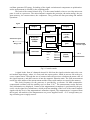
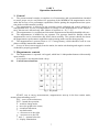
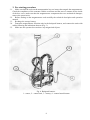
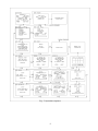
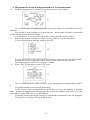
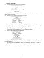
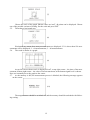
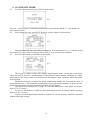
Ministry of Natural Resources of Russian Federation Federal State Unitary Research &Production Enterprise «Geologorazvedka» MINIMAG-M (new edition) Portable Proton Magnetometer User manual St. Petersburg Contents Page Introduction ………………………………………………………....……………… 3 PART 1. Technical description …………………………………………..………… Functions …………………………………………………………....……………… Technical characteristics ………………………………………………....………… Complete set of the MINIMAG magnetometer ………………………….………… Arrangement and operation of the magnetometer ………………………..………… Principle of operation …………………………………………………….………… Block diagram ……………………………………………………………………… 3 PART 2. Operation instruction ……………………….......………………………… 1. General ………………………………………………………..……………………. 2. Magnetometer controls …………………………………………………….……….. Control button functions ………………………………………………….………… 3. Pre-starting procedure ……………………………………………………………… 4. Magnetometer turn-on and performance of test measurement ………………...…… 5. Manual mode ………………………………………………………………..……… 6. Automatic mode ……………………………………………………….…………… 7. Data view ………………………………………………………………..………….. 8. Data output …………………………………………………………….…………… 9. ERASE ………………………………………………………………….………….. 10. Scan mode ……………………………………………………………….…………. 11. Battery operating instruction …………………………………………......………… Battery charging ……………………………………………………………………. Precautions ………………………………………………………….……………… Storage ………………………………………………………………..…………….. 7 1. 2. 3. 4. 2 3 3 4 5 5 5 7 7 7 8 10 11 13 14 14 15 15 16 17 17 17 Introduction MINIMAG-M is an upgraded variant of portable single-channel proton magnetometer with a simplified control circuit, designed for a wide variety of applications in mineral exploration, as well as for detection of buried magnetized objects. It can also be used as a self-contained base station magnetometer (geomagnetic-variation system) with a programmable working cycle with a maximum sampling rate of 1 reading per 2 seconds. In spite of its small size MINIMAG-M has sufficiently high metrological characteristics which ensure high-accuracy magnetic survey. At the basis of its development is the present-day ideology of the design of field magnetic instrument, which involves employment of microprocessor control and accumulation of digital data in the memory. The MINIMAG-M development program, a joint effort of “Geologorazvedka” Enterprise and “Geomer” Center, was completed in 2009. Compared to previous modification of MINIMAG, the new one has easies control protocol and more reliable maintainability. New LCD display is bigger and has better contrast than the one of the previous generation. The graph of the recorded field is shown on the display now. And the memory is increased 8 times, what reduces limitations of the use of magnetometer. Digital data output is performed via RS-232 or USB. Magnetometer kit is supplemented by remote launch button for convenience in case of survey performance by one operator. The present manual consists of two parts. In the first part (technical description) the user is introduced to the principle of operation and the design of the magnetometer; the second part (operation instructions) contains basic recommendations on the instrument operation under field conditions. PART 1 Technical description 1. Functions 1.1. The MINIMAG-M portable proton magnetometer is designed to measure the absolute value (T) of the Earth’s magnetic field in carrying out ground magnetic survey operations and detections of buried ferrous objects. 1.2. The main restrictions on the operations with magnetometer and high level of electromagnetic (industrial) noise and heterogeneity of measured field. Maximum gradient should not exceed 5000nT/m. Without special precautions it should not be used under vibrations and shaking. 2. Technical characteristics Total field measurement range: 20 to 100 T with a reading error 0.01 nT The limit of the basic systematic error of total field measurements over the entire range: no more than ±2 nT 2.3. The limit of the root-mean-square error in total field measurements does not exceed 0.03 nT over the range from 30 to 100 T and 0.1 nT over the range from 20 to 30 T. 2.4. Magnetometer drift with time does not exceed ±0.2 nT over 8 hours of continuous operation. 2.5. The magnetometer has a manual operation mode and an automatic measurement mode with a working cycle programmable from 2 seconds to 24 hours in 1 s steps; one measurement time does not exceed 2 s. 2.6. Operating conditions setting time – no longer than 1 minute. 2.7. Internal real-time clock instability – no greater than 1 second over 24 hours. 2.8. The magnetometer has an external power supply of 13 2 V (storage battery); variations in magnetometer indications with power-supply variations from 11 V to 15 V do not exceed ±0.2 nT; an average power consumption at 10 s intervals does not exceed 1 W. 2.1. 2.2. 3 The sensor operating angle is 45 from the optimum orientation (when the sensor lowfrequency coil axis is orthogonal to the magnetic field vector); an additional error due to sensor orientation deviation from the optimum by an angle of 45 is no greater than ±1 nT. 2.10. The information stored in the magnetometer memory: magnetic intensity at each station accompanied by the reliability parameter (D)* of the measurement; reading order number; reading time; auxiliary information entered by the operator(date, site number, starting number) 2.11. The memory capacity allows to store about 500 000 readings in the walking mode of operation and no less than 1 000 000 readings in the base station mode; 2.12. The information stored in the memory can be output to a PC via the RS-232 or USB interface; 2.13. Operating temperature range: - 10C … + 50C; the magnetometer drift over the operating temperature range does not exceed ±0.5 nT; 2.14. Weight of the complete working outfit does not exceed 4 kg 2.9. 3. Complete set of the MINIMAG magnetometer Designation тт2.809.015-01 тт3.036.021-01 LC-123R4PG ГРПА.468363.004 ГРПА.468363.001 ГРПА.468363.167 Name Assembly units Magnetometric transducer Control console Storage battery Cable connecting megnetometric transducer and control console Power supply cable Remote launch button cable Quantity 1 1 1 1 1 1 1 1 1 1 1 1 1 ГРПА468.363.002 ГРПА468.363.005 US232B Accessories Storage battery Battery charger Backpack harness Case RS-232 cable Power supply cable (additional) Cable RS232-USB тт4.161.044 Packing box 1 тт1.420.087-01 РЭ тт1.420.087-01 ФО Documentation Operation manual Record of calibration service CD-R with the data input program 1 1 1 LC-123R4PG ТУ3468-005-39491876-99 ГРПА301.549.002-01 Notes Packing * D is a conditional parameter, which is characteristic of the spread of the precession signal period or signal-to-noise ratio; it is expressed in numerals from 0 to 9 (when D=0 to 2 – signal is normal; when D>2 – signal is degraded, at D=9 there is no signal) 4 4. Arrangement and operation of the magnetometer 4.1. Principle of operation The magnetometer measurements are based on free precession of polarized protons in sensor under magnetic field influence. The polarization is based on the Overhauser effect. Each measurement cycle consists of two periods. First period – polarization: DC and high-frequency magnetic fields act on the sensor working substance so that the proton spin axes turn perpendicular to the Earth’s magnetic field vector. Second period – measurement: polarization is turned off, and protons begin to precess around the Earth’s magnetic field vector. As a result, a damped sinusoid shaped signal EMF is induced in HF-coils of the sensor. The frequency of the sinusoid is proportional to the magnetic intensity: T F where: F – frequency of the precession signal T – magnetic intensity – proton gyromagnetic ratio If F – Hz, T – nT; then = 23,487189 nT/Hz The signal is amplified in the signal excitation unit, and in the control console the precession signal frequency is measured and converted into the magnetic field value. 4.2. Block diagram The magnetometer consists of three main blocks: the magnetometric transducer comprising the sensor and the signal excitation unit, the control console and the storage battery power supply. Signal excitation unit Sensor Signal HF-circuit 1) e Working n substance s o LF-coils r H-F oscillator Signal amplifier Polarization pulse +12 V Switch Capacitor bank Range code Fig. 1. Magnetometric transducer The sensor is designed to obtain a signal of free precession of protons placed into the magnetic field to be measured. The sensor (Fig. 1) comprises a glass ampoule with the working substance located in a highfrequency circuit. Over the HF circuit the low-frequency coils are wound. During polarization, a low d.c. bias current is applied to the LF-coils, and high-frequency energy to the HF circuit. When polarization is turned off, EMF of a signal of a damped sinusoid shape is induced in the LF-coils. The signal excitation unit comprises a HF-oscillator and a signal generator board. The latter contains a switching node, a bank of trimming capacitors, and a signal amplifier. The trimmer capacitor bank and sensor LF-coils form a series oscillatory circuit tuned to the signal frequency. Tuning is effected by the processor based on the previous measurement result. The precession signal is amplified and fed to the control console for measurement. During polarization the HF5 oscillator generates HF energy. Switching of the signal excitation unit components to polarization and to measurement is effected by the switching node. The basis of the control console (Fig. 2) is the control module, where a one-chip microcomputer is used as a processor. The microcomputer contains the processor, the main storage, the program memory, the counter-timers, the comparator. They perform all data processing and transfer operations. Signal Shaper Polarization pulse Processor Reference oscillator 5 MHz Memory Range code Keypad Display Piezoelectric ceramics aural indicator indicator RS-232 port RS-232 output Level converter +12,6 V +10 V +5 V Secondary power suppply +13 V -8 V Fig.2. Control console A signal in the form of a damped sinusoid is fed from the signal excitation unit to the control module input shaper, where it is converted into square pulses, which in turn are fed to the processor counter-timers. Through the use of counter-timers the processor calculates the mean value of the signal frequency, and then converts it into the magnetic induction units. The field measurement results, the time instant of the measurement and the frame serial number are stored in the memory. The clock frequency for the processor is provided by a reference 20 MHz temperaturecompensated oscillator with the stability not less than 2*10-6. The measurement results and auxiliary information are displayed. Control of the magnetometric transduser is performed by the processor via the signal level transformer, which performs matching of the level of the control module signals with the level of the magnetometric transducer signals. The magnetometer is operated from the keypad. All modules of the magnetometer are power supplied from a +12 V storage battery using secondary power supply sources. 6 PART 2 Operation instruction 1. General 1.1. The present manual contains a complete set of instructions and recommendations intended to assure proper service and failure-free operation of the MINIMAG-M magnetometer and to make the best use of its performance capabilities. Before putting the magnetometer into operation mode read this manual carefully. 1.2. The magnetometer is delivered to the customer tested, calibrated and sealed, packed in a transportation box. In case of transportation or storage of the magnetometer at low temperatures, the turn-on is allowed only after 4 hours of exposure at + 20 ÷ ± 5°C. 1.3. The magnetometer is a sophisticated electronic instrument and should be handled with care. 1.4. The magnetometer is handled by one operator. The operator should be familiar with the magnetometer service instructions and follow them carefully. The operator should also know the magnetometer performance capabilities and operating modes and use them properly. 1.5. The magnetometer is powered from a +12 V storage battery, which should be used in compliance with the instructions attached. 1.6. In case of direct current supply from the mains, the mains unit housing and negative terminal should be properly grounded. 2. Magnetometer controls 2.1. The magnetometer is operated via keypad, which has 18 independent buttons with normally open contacts. A keystroke is accompanied with a beep. 2.2. Control button functions Fig. 3. Keyboard START –test or survey measurements, magnetometer start-up in the base station mode, memory data unloading to a PC; ESC – move to the main menu; ENT – launch the operation; F – switch to image mode; – move the graph to the center; - second measurement; - step backwards; - cursor move to the right - cursor move to the left and - numeral selection ☼ - display illumination 7 3. Pre-starting procedure 3.1. Make sure that the seals on the transportation box are intact, then unpack the magnetometer. Check the compliance of the contents with the certificate and the note of contents on the inside of the box cover; make sure that the magnetometer components have no mechanical damages; remove the preservative. 3.2. Before turning on the magnetometer read carefully the technical description and operation manual. 3.3. Recharge the storage battery. 3.4. Fasten the magnetometer function units in the backpack harness, and connect the units with cables following the indications thereon (Fig. 3). 3.5. Make sure the operator does not have any magnetized objects. Fig. 4. Backpack harness. 1 – sensor, 2 – control unit, 3 – battery, 4 - remote launch button 8 Fig. 5. Operation sequence 9 4. Magnetometer turn-on and performance of test measurement 7.1. When the magnetometer is switched on the display shows setup window: (1) «I» - cursor for date, time and number of the survey area setting. To set the data use numeric keyboard. Date should be in day-month-year format and time - hours-minutes-seconds. to launch the set time and information press ENT button. As a default date is not set and the time will be counted from the switch-on time. 7.2. After setting the date and time press ENT, then press ESC to go to the main menu. To go to the main menu from any window press ESC. (2) 7.3. To enter the selection of any mode type N ENT, where N is the number of the chosen mode. Pressing ESC for the second time in main menu switches display to setup window. At dark time display can be lit by pressing «¤» button. Press 1 ENT in main menu to enter TEST mode: (3) The test measurements are made in order to check signal quality and magnetometer usability. Test measurements are not stored in the memory. In TEST mode a series of measurements can be done (in N type the quantity of measurements). In that case magnetometer will automatically measure the magnetic field each 2 s N times and calculate average field value (Tavg) and RMS (). For quality control power supply voltage (U) and current consumption (I) are also displayed. The signal level is shown as decaying black stripe. 10 5. MANUAL MODE 5.1. To enter manual mode press 3 ENT in main menu: (4) Line number and point number can be set here. With ↑ or ↓ chose either ascending or descending numbering of points. 5.2. Press ENT twice. Ready to work window will be shown: (5) Magnetometer will show the values of magnetic field measured every 2 s (without saving into memory), current time and position (line and point) and signal level indication in form of shaded decaying line. For quality control power supply voltage (U) and current consumption (I) are also displayed. The number of the station does not change therewith. If error occurs in any data shown press ↑ to go to the previous window. 5.3. Press START button to launch the measurement: (6) Magnetic field value, time and coordinates will be stored in memory. Point number is automatically changed when measuring magnetic field next time. If another measurement is needed at the same point press ↓. All measurement performed on one point are saved in memory. The last one is counted as most reliable. When the last measurement is done on the line, press ↑ to set next line and point number (go to setup display 4). 5.4. The result can be displayed as a graph. To enter that mode press F: 11 (7) Choose the scale of the graph. Shown values are in nT. 40 points can be displayed. Choose one of the possible variants of scaling. Set the scale and press ENT. 5.5. Then choose horizontal step: (8) Horizontal step means how many measurements are displayed. If 1 is chose then 120 measurements will be displayed, 2 – 60 measurements, 3 – 40 measurements. 5.6. The result is shown as a graph: (9) At top left corner chosen scale is displayed in nT, at top right corner – the time of last measurement, bottom right corner – the value of last measurement, at the bottom signal level is shown. Press to manually move the graph to the center. 5.7. As the memory is full, the measurement process is blocked; the following message appears on the screen: (10) The magnetometer should be switched off, and the memory should be unloaded with following erasing. 12 6. AUTOMATIC MODE 8.1. To enter automatic mode press 4 ENT in main menu: (11) Set cycle – period of time of automatic launching the measurements and M-T – route number or base station position. 8.2. After setting the cycle, press ENT. Ready to operate window will be shown: (12) Magnetometer will show the values of magnetic field measured every 2 s (without saving into memory). If error occurs in any data shown press ↑ to go to the previous window. 8.3. Press START button to launch the measurement: (13) The screen is similar to that of the manual measurements mode, except that a root-meansquare error () of the last 15 measurements will be displayed rather than the reliability of a single measurement. The value of this error characterizes the magnetic field variations, which take place at the moment. Should the need arise to change the initial measurement number, the cycle and the series of measurements press ↑. The automatic measurement process will be discontinued. To proceed to automatic measurements with new parameters, push the START button. The result can be displayed as a graph. To enter that mode press F and follow the instructions in 5.4-5.6 section. As soon as the memory is filled up, the measurement process is blocked and the message appears as in 5.7 section. In this case the magnetometer should be turned off, and the memory should be unloaded with the following erasing. 13 7. DATA VIEW 7.1. To enter data view mode press 2 ENT in main menu: (14) Using the cursor control keys ← or → and ↑ or ↓ set the date and the time of the data to be reviewed. Press ENT. 7.2. The information of the frame nearest to the specified time will be displayed on the screen. To review the consecutive readings stored in the magnetometer memory within the specified date before or after the specified time, push the ↓ or ↑ keys. 7.3. If the date is not specified (the default value is 0), all readings stored in the memory will be available for review. 8. DATA OUTPUT 8.1. To output data use RS-232 cable or RS-232 with USB connector. It is recommended to disconnect the control unit from the battery. Turn on the PC and launch the supplied with magnetometer minimag-m.exe utility. Choose the COM-port that the magnetometer is attached to and press IMPORT DATA. 8.2. Turn on the magnetometer and choose UPLOAD mode by pressing 5 ENT in main menu: (15) Using the cursor control keys ← or → and the numeral selection keys ↑ or ↓ , specify the date, the information of which is to be unloaded. If the date is not specified (zero values), all the information stored in the memory will be output. 8.3. The data array of this date will be output to the computer: (16) When the data output is accomplished, the computer input program is closed by the ESC command. 8.4. The exported data can be viewed on PC: If the data is exported from automatic mode datasheet will contain 2 columns – magnetic field value and time of measurement. If the data is exported from manual mode each measurement will have 4 parameters – magnetic field value, time of measurement, point number and line number. 14 The heading of datasheet will consist of survey area number and date. Data from automatic mode will also have cycle of measurements, route number or base station position information. Exported data is saved to PC memory and can be reshown later. 9. ERASE 9.1. To erase the information go to main menu and press 6 ENT. The following window will be displayed: (17) 9.2. Erasing data cannot be undone. After pressing ENT window will switch to dialog: (18) After this procedure the display will show setup menu, in case ESC button was pressed main menu will be shown. 10. SCAN MODE 10.1. To enter scan mode go to main menu and press 7 ENT. After that press 2 ENT to see the dialog: (19) Scan mode is designed for cases, when magnetometer is not able to detect signal. It may happen when, for example gradient of measuring field is so great (>10 000 nT), the sensor cannot adjust the measuring field. 10.2. When this mode is launched the device will automatically measure magnetic field in different ranges (measuring each second) choosing the one with biggest amplitude and smallest D parameter. The end of scanning is indicated with a signal. After that press ESC to go to the main menu and continue measurements. 10.3. If the D parameter is still unsatisfying (> 3-4) that meant the sensor in located in highly gradient field. The position of the sensor should be changed. 15 11.Battery operating instruction Achievable capacity (%) 11.1. The magnetometer operates from a non-magnetic sealed lead – acid storage battery of the LC-R123R4PU type with a capacity of 3.4 Ah. Operating temperature conditions: Charge: 0ºC to +40ºC Discharge: -15ºC to +50ºC Storage: -15ºC to +40ºC Normal operating conditions: +25ºC. 11.2. The average service life of the battery may vary from 3 to 5 years depending on operating conditions; e.g. the service life extends considerably as the degree of discharge is reduced (Fig. 5). That is why it is not advisable to discharge the battery to a degree lower than 50 % of the rated capacity. (Degree of discharge 100 %) (Degree of discharge 50 %) (Degree of discharge 30 %) Temperature 25ºС 0 200 400 600 800 1000 1200 1400 Number of charge-discharge cycles Fig. 6. Service life in charge-discharge cycles 11.3. The degree of charge (discharge) of the battery can be assessed with the use of the plot in Fig. 6 through measuring the voltage of the battery at no-load. Volts Voltage at no-load 13,2 Conditions: 24 hours after charge 10 minutes after discharge Temperature 25ºC 12,6 12,0 11,4 2 50 Residual capacity (%) Fig. 7. Voltage versus residual capacity 16 100 % 11.4. In order to assure sufficient reliability the following conditions should be met: the voltage measurement should be made not before than 24 hours after the previous charging and not before than 10 minutes after turning – off the load; measurements should be made at room temperature; if the battery has been used at low temperatures, it should be exposed at room temperature for 2 - 3 hours. It should be remembered that the storage battery capacity is heavily dependent on the ambient temperature. For instance, at an average discharge current of 0.1 A and ambient temperature 8ºC the battery capacity will amount to about 65 % of the rated value, while at -20ºC it will be about 50 %. 11.5. Battery charging Battery charging should be performed at room temperatures with the use of the automatic charger supplied with the standard service kit. The battery charger operating instructions are given in the attached certificate. Charging process is indicated with the red light and when the battery is charged - green light. In the absence of the battery charger, it is allowed to apply a constant current source with a controllable voltage and provided with a test ammeter. As with any type of acid storage batteries, the optimum charging current is estimated at 0,1 of the battery capacity, i.e. here it is about 0.7 -0.9 A. In case of emergency, a rapid charging is permissible. It should be remembered, however, that the increase of the charging current results in significant decrease of the battery capacity. 11.6. Precautions All safety precautions pertaining to the application of lead-acid cells, should be observed in operation of the storage battery. The battery should be protected from shocks which may cause damage to leak-proofness and eletrolyte leaks. Operation of the battery in small, closed, unventilated rooms, close to heat sources and in direct sunlight is not allowed. The use of the battery upside-down is not advisable. In order to avoid short circuit and excessive current leakage, the battery terminals and the surface in between should be kept clean. 11.7. Storage The battery may be stored at temperatures from -15ºC to +40ºC. The battery terminals should be at no-load. The battery is liable to self-discharge. The rate of self-discharge increases with increasing temperature. Therefore, the battery should be recharged at least once every 6 mouths. 17