1
User Manual
DSPC-8661-PCXE
DSPC-8662-PCXE
Linux Programming Guide
Copyright
The documentation and the software included with this product are copyrighted 2012
by Advantech Co., Ltd. All rights are reserved. Advantech Co., Ltd. reserves the right
to make improvements in the products described in this manual at any time without
notice. No part of this manual may be reproduced, copied, translated or transmitted
in any form or by any means without the prior written permission of Advantech Co.,
Ltd. Information provided in this manual is intended to be accurate and reliable. However, Advantech Co., Ltd. assumes no responsibility for its use, nor for any infringements of the rights of third parties, which may result from its use.
Acknowledgements
Intel and Pentium are trademarks of Intel Corporation.
Microsoft Windows and MS-DOS are registered trademarks of Microsoft Corp.
All other product names or trademarks are properties of their respective owners.
Product Warranty (2 years)
Advantech warrants to you, the original purchaser, that each of its products will be
free from defects in materials and workmanship for two years from the date of purchase.
This warranty does not apply to any products which have been repaired or altered by
persons other than repair personnel authorized by Advantech, or which have been
subject to misuse, abuse, accident or improper installation. Advantech assumes no
liability under the terms of this warranty as a consequence of such events.
Because of Advantech’s high quality-control standards and rigorous testing, most of
our customers never need to use our repair service. If an Advantech product is defective, it will be repaired or replaced at no charge during the warranty period. For outof-warranty repairs, you will be billed according to the cost of replacement materials,
service time and freight. Please consult your dealer for more details.
If you think you have a defective product, follow these steps:
1. Collect all the information about the problem encountered. (For example, CPU
speed, Advantech products used, other hardware and software used, etc.) Note
anything abnormal and list any onscreen messages you get when the problem
occurs.
2. Call your dealer and describe the problem. Please have your manual, product,
and any helpful information readily available.
3. If your product is diagnosed as defective, obtain an RMA (return merchandize
authorization) number from your dealer. This allows us to process your return
more quickly.
4. Carefully pack the defective product, a fully-completed Repair and Replacement
Order Card and a photocopy proof of purchase date (such as your sales receipt)
in a shippable container. A product returned without proof of the purchase date
is not eligible for warranty service.
5. Write the RMA number visibly on the outside of the package and ship it prepaid
to your dealer.
Part No. 2002866100
Edition 1
Printed in Taiwan
September 2012
DSPC-8661/8662-PCXE User Manual
ii
Declaration of Conformity
CE
This product has passed the CE test for environmental specifications when shielded
cables are used for external wiring. We recommend the use of shielded cables. This
kind of cable is available from Advantech. Please contact your local supplier for
ordering information.
CE
This product has passed the CE test for environmental specifications. Test conditions
for passing included the equipment being operated within an industrial enclosure. In
order to protect the product from being damaged by ESD (Electrostatic Discharge)
and EMI leakage, we strongly recommend the use of CE-compliant industrial enclosure products.
FCC Class A
Note: This equipment has been tested and found to comply with the limits for a Class
A digital device, pursuant to part 15 of the FCC Rules. These limits are designed to
provide reasonable protection against harmful interference when the equipment is
operated in a commercial environment. This equipment generates, uses, and can
radiate radio frequency energy and, if not installed and used in accordance with the
instruction manual, may cause harmful interference to radio communications. Operation of this equipment in a residential area is likely to cause harmful interference in
which case the user will be required to correct the interference at his own expense.
FCC Class B
Note: This equipment has been tested and found to comply with the limits for a Class
B digital device, pursuant to part 15 of the FCC Rules. These limits are designed to
provide reasonable protection against harmful interference in a residential installation. This equipment generates, uses and can radiate radio frequency energy and, if
not installed and used in accordance with the instructions, may cause harmful interference to radio communications. However, there is no guarantee that interference
will not occur in a particular installation. If this equipment does cause harmful interference to radio or television reception, which can be determined by turning the equipment off and on, the user is encouraged to try to correct the interference by one or
more of the following measures:
Reorient or relocate the receiving antenna.
Increase the separation between the equipment and receiver.
Connect the equipment into an outlet on a circuit different from that to which the
receiver is connected.
Consult the dealer or an experienced radio/TV technician for help.
FM
This equipment has passed the FM certification. According to the National Fire Protection Association, work sites are classified into different classes, divisions and
groups, based on hazard considerations. This equipment is compliant with the specifications of Class I, Division 2, Groups A, B, C and D indoor hazards.
iii
DSPC-8661/8662-PCXE User Manual
Technical Support and Assistance
1.
2.
Visit the Advantech web site at www.advantech.com/support where you can find
the latest information about the product.
Contact your distributor, sales representative, or Advantech's customer service
center for technical support if you need additional assistance. Please have the
following information ready before you call:
– Product name and serial number
– Description of your peripheral attachments
– Description of your software (operating system, version, application software,
etc.)
– A complete description of the problem
– The exact wording of any error messages
Safety Instructions
1.
2.
3.
4.
5.
6.
7.
8.
9.
10.
11.
12.
13.
14.
15.
16.
17.
18.
19.
20.
21.
Read these safety instructions carefully.
Keep this User Manual for later reference.
Disconnect this equipment from any AC outlet before cleaning. Use a damp
cloth. Do not use liquid or spray detergents for cleaning.
For plug-in equipment, the power outlet socket must be located near the equipment and must be easily accessible.
Keep this equipment away from humidity.
Put this equipment on a reliable surface during installation. Dropping it or letting
it fall may cause damage.
The openings on the enclosure are for air convection. Protect the equipment
from overheating. DO NOT COVER THE OPENINGS.
Make sure the voltage of the power source is correct before connecting the
equipment to the power outlet.
Position the power cord so that people cannot step on it. Do not place anything
over the power cord.
All cautions and warnings on the equipment should be noted.
If the equipment is not used for a long time, disconnect it from the power source
to avoid damage by transient overvoltage.
Never pour any liquid into an opening. This may cause fire or electrical shock.
Never open the equipment. For safety reasons, the equipment should be
opened only by qualified service personnel.
If one of the following situations arises, get the equipment checked by service
personnel:
The power cord or plug is damaged.
Liquid has penetrated into the equipment.
The equipment has been exposed to moisture.
The equipment does not work well, or you cannot get it to work according to the
user's manual.
The equipment has been dropped and damaged.
The equipment has obvious signs of breakage.
DO NOT LEAVE THIS EQUIPMENT IN AN ENVIRONMENT WHERE THE
STORAGE TEMPERATURE MAY GO BELOW -20° C (-4° F) OR ABOVE 60° C
(140° F). THIS COULD DAMAGE THE EQUIPMENT. THE EQUIPMENT
SHOULD BE IN A CONTROLLED ENVIRONMENT.
DSPC-8661/8662-PCXE User Manual
iv
22. CAUTION: DANGER OF EXPLOSION IF BATTERY IS INCORRECTLY
REPLACED. REPLACE ONLY WITH THE SAME OR EQUIVALENT TYPE
RECOMMENDED BY THE MANUFACTURER, DISCARD USED BATTERIES
ACCORDING TO THE MANUFACTURER'S INSTRUCTIONS.
23. The sound pressure level at the operator's position according to IEC 704-1:1982
is no more than 70 dB (A).
DISCLAIMER: This set of instructions is given according to IEC 704-1. Advantech
disclaims all responsibility for the accuracy of any statements contained herein.
Safety Precaution - Static Electricity
Follow these simple precautions to protect yourself from harm and the products from
damage.
To avoid electrical shock, always disconnect the power from your PC chassis
before you work on it. Don't touch any components on the CPU card or other
cards while the PC is on.
Disconnect power before making any configuration changes. The sudden rush
of power as you connect a jumper or install a card may damage sensitive electronic components.
v
DSPC-8661/8662-PCXE User Manual
DSPC-8661/8662-PCXE User Manual
vi
Contents
Chapter
Chapter
1
Introduction..........................................1
1.1
1.2
Overview ................................................................................................... 2
Key Acronyms and Vocabulary ................................................................. 2
2
Package Content .................................3
Table 2.1: Package content list ................................................... 4
Chapter
Chapter
Chapter
Chapter
3
Installation............................................5
3.1
3.2
3.3
3.4
3.5
Host System Requirement ........................................................................ 6
Build Instruction......................................................................................... 6
3.2.1 Build and install driver................................................................... 6
3.2.2 Build boot loader utility.................................................................. 7
3.2.3 Build V4L2-Like example code ..................................................... 7
Driver Usage ............................................................................................. 7
Boot Loader Utility Usage ......................................................................... 8
V4L2-Like Example Application Usage ..................................................... 9
4
PCIe EP Boot Driver ..........................11
4.1
4.2
4.3
Features Supported ................................................................................ 12
Supported IOCTLs .................................................................................. 12
Table 4.1: Driver I/O control code list ........................................ 12
4.2.1 TI81XX_PCI_GET_BAR_INFO................................................... 12
4.2.2 TI81XX_PCI_SET_BAR_WINDOW............................................ 13
4.2.3 TI81XX_PCI _DWNLD_DONE ................................................... 13
Source Files ............................................................................................ 13
5
PCIe EP Boot Application .................15
5.1
5.2
5.3
Features Supported ................................................................................ 16
Features NOT Supported........................................................................ 16
Source Files ............................................................................................ 16
6
Video For Linux 2 - Like Driver.........17
6.1
6.3
6.4
Features Supported for Basic V4L2 ioctl() handling................................ 18
Table 6.1: ioctl parameters for Video For Linux II...................... 18
Extended Features.................................................................................. 19
6.2.1 Pixel Format in VIDIOC_G_FMT and VIDIOC_S_FMT .............. 19
6.2.2 Private Control Command........................................................... 19
Features NOT supported ........................................................................ 20
Audio Supported ..................................................................................... 21
7
Video For Linux 2 Sample Code.......23
7.1
7.2
Programming Structure ........................................................................... 24
Procedure................................................................................................ 24
6.2
Chapter
vii
DSPC-8661/8662-PCXE User Manual
7.2.1
7.2.2
7.2.3
7.2.4
7.2.5
7.2.6
7.2.7
7.2.8
Open the device.......................................................................... 24
Properties Negotiation ................................................................ 24
Pixel Format and Image Size Negotiation. ................................. 25
Request Buffers and Query Buffer Using Memory mapping....... 25
Getting audio data ...................................................................... 26
Main loop .................................................................................... 27
Private control command settings............................................... 27
Close the device. ........................................................................ 27
DSPC-8661/8662-PCXE User Manual
viii
Chapter
1
Introduction
1
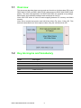
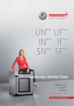
1.1 Overview
This document describes how to set up and use linux driver for Netra-base PCIe card
DSPC-8661-PCXE and DSPC-8662-PCXE (abbreviated as DSPC-8661/DSPC-8662
below). The driver and application for DSPC-8661/8662 are released as a package.
Below figure show software package stack developed in host PC.
Linux host PCIE driver is used to create mapping between PC memory and Netra
memory.
Linux driver contain boot portion and V4L2-Like (Video For Linux 2 Like) API. This
document described here, allow capture video using the v4l2-like driver API.
1.2 Key Acronyms and Vocabulary
Terms
Description
Netra
TI DM8168
PCIe
PCI-Express
EP
PCIe Endpoint
RC
PCIe Root Complex
V4L2
Video for Linux II
V4L2-Like
Video for Linux II with additional function
DSPC-8661/8662-PCXE User Manual
2
Chapter
2
Package Content
2
This package is created in Linux to help customer quickly boot Netra through PCIE,
the package includes:
Table 2.1: Package content list
Path
Purpose
driver
Linux boot and V4L2-Like driver
utility
Boot Loader Utility included pre-built board u-boot, kernel image
and filesystem.
V4l2_samples-0.4.1
V4L2-Like (Video for Linux 2 Like) sample code modified by
Advantech.
DSPC-8661/8662-PCXE User Manual
4
Chapter
3
Installation
3
3.1 Host System Requirement
A reference of the OS used to develop and execute this software release is:
1. Linux distribution: Ubuntu 10.04 LTS.
2. Kernel: Linux kernel version 2.6.35.22. In fact, the driver should work with any
kernel with version >=2.6.20.
3.2 Build Instruction
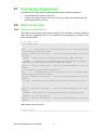
3.2.1 Build and install driver
The driver is closely tied to Linux kernel running on PC, therefore, it must be rebuilt to
work with the supporting kernel. The command and messages for building PCIE
driver is listed below:
# cd {pkage_dir}/
# sh install.sh
make
-C /lib/modules/2.6.32-38-generic/build M=/home/user/
src/ti816x_pcie/driver clean
make[1]: Entering directory `/usr/src/linux-headers-2.6.32-38generic'
CLEAN
/home/user/src/ti816x_pcie/driver/.tmp_versions
CLEAN
/home/user/src/ti816x_pcie/driver/Module.symvers /
home/user/src/ti816x_pcie/driver/modules.order
make[1]: Leaving directory `/usr/src/linux-headers-2.6.32-38generic'
rm -rf modules.order Module.markers
make
-C /lib/modules/2.6.32-38-generic/build M=/home/user/
src/ti816x_pcie/driver modules
make[1]: Entering directory `/usr/src/linux-headers-2.6.32-38generic'
CC [M] /home/user/src/ti816x_pcie/driver/ti816x_pcie_drv.o
...
...
make[1]: Entering directory `/usr/src/linux-headers-2.6.32-38generic'
INSTALL /home/user/src/ti816x_pcie/driver/ti816x_pcie.ko
DEPMOD 2.6.32-38-generic
make[1]: Leaving directory `/usr/src/linux-headers-2.6.32-38generic'
User need to reboot Host PC
# sudo reboot
DSPC-8661/8662-PCXE User Manual
6
The command for building boot application is listed below:
# cd util
# make clean
# make
Chapter 3
3.2.2 Build boot loader utility
Make boot application as executable:
3.2.3 Build V4L2-Like example code
The command for building V4L2-Like example code is listed below:
# cd V4l2-example.x.x
# make clean
# make
Make example code as executable:
# chmod a+x capturer_mmap
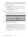
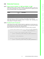
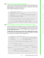
3.3 Driver Usage
Linux host PCIE driver is used to create mapping between PC memory and Netra
memory. The device information is shown by dmesg command.
After finishing previous steps, users can run the following boot application and V4L2Like example code to access boot driver directly without “insmod”.
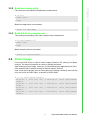
User could check devices node in files system as following command, there will be
only one device for DSPC-8661, 4 devices for DSPC-8662.
# ls -al /dev/ti81xx/ti816x-*
crw-rw-rw- 1 root root 251,
ti816x-0
crw-rw-rw- 1 root root 251,
ti816x-1
crw-rw-rw- 1 root root 251,
ti816x-2
crw-rw-rw- 1 root root 251,
ti816x-3
0 2012-03-12 16:32 /dev/ti81xx/
1 2012-03-12 16:32 /dev/ti81xx/
2 2012-03-12 16:32 /dev/ti81xx/
3 2012-03-12 16:32 /dev/ti81xx/
7
DSPC-8661/8662-PCXE User Manual
Installation
# chmod a+x saBootApp
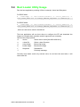
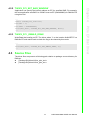
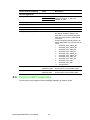
3.4 Boot Loader Utility Usage
Run the boot application providing U-Boot, bootscript, kernel and filesystem:
For DSPC-8661:
# ./saBootApp -d /dev/ti81xx/ti816x-0 -u u-boot_8661.bin -s
boot_ramfs_8661.scr -k uImage_DM816X_sdpc8661 -f ramdisk.gz
For DSPC-8662:
# ./saBootApp -d /dev/ti81xx/ti816x-n -u u-boot_8662.bin -s
boot_ramfs_8662.scr -k uImage_DM816X_sdpc8662 -f ramdisk.gz
, which n is the device exist in /dev/ti81xx/.
The boot application will use boot driver to configure the EP and download the
images to complete boot operation and all arguments are necessary.
Here are the usage options:
-d
device
Select device name [/dev/ti81xx/ti816x-n]
-u
u-boot file
Select u-boot file name
-s
script image
Boot script image
-k
kernel image
Boot kernel image
-f
filesystem
Ramdisk file
-?
Print help message.
Currently boot loader could only execute once, do not boot the card twice, it will
cause card fail.
DSPC-8661/8662-PCXE User Manual
8
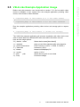
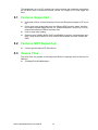
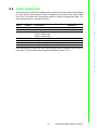
Before using this example, user should refer to section 7.2.1 find out which video
device is available in your system. Run the example application providing video
device, video format or video standard.
# ./capturer_mmap -D /dev/video0 -p 0 // set video format
or
# ./capturer_mmap -D /dev/video0 -s 0// set video standard
# ./capturer_mmap -D /dev/video0 -f {folder for storage}
The V4L2-Like example application will process negotiation with video device and
start to stream data from dedicated EP then store data to the folder user set.
Here are the usage options:
-D | --device name
Select device name [/dev/video0]
-s | --standard
show current Video standard after auto-detection
-p | --pixel-formatnumber
Pixel Format (0 = H264, 1 = RAW, 2 = MJPG )
-F | --framerate
framerate:1~30"\n"
-b | --bitrate
bitrate:64~2000(Kbps)"\n"
-q | --quality
quality:1~30"\n"
-f | --path
path
Select directory path to store data
-h | --help
Print this message
9
DSPC-8661/8662-PCXE User Manual
Installation
Run the example application providing video device and storage path to capture
data:
Chapter 3
3.5 V4L2-Like Example Application Usage
DSPC-8661/8662-PCXE User Manual
10
Chapter
4
4
PCIe EP Boot Driver
This driver runs on x86 PC running Linux kernel 2.6.32 onwards. It will configure
each DM816x/DM814x EP device detected in the system and configures them to be
able to carry boot operation. This API is included by default in the 2.6 kernel series.
4.1 Features Supported
Support for detecting and configuring each DM816x device to device node in
Linux file-system.
Provides character device interface on Linux Kernel to PCIe boot user-space
application
Provide mmap support to enable the boot application to copy image files (UBoot, kernel etc) to EP memory
Can be built as loadable module or into kernel
4.2 Supported IOCTLs
It is a Linux based PCIE driver which is used to map between PC memory and
DM8168 memory, the implemented I/O control is listed below, The IOCTL and data
structure declarations are in drivers/ti816x_pcie_drv.h file in release package source.
Table 4.1: Driver I/O control code list
IOCTL code
Description
TI816X_PCI_IOCTL_DWNLD_DONE
Write/Read to boot control flag for checking
boot status.
TI816X_PCI_IOCTL_SET_BAR_WINDOW
Change the memory address mapping of the
specified window
TI816X_PCI_IOCTL_GET_BAR_INFO
Get the current BAR information of the specified window
TI816X_PCI_BUF_SETOB
TBD
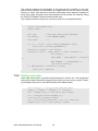
4.2.1 TI81XX_PCI_GET_BAR_INFO
Returns the size in bytes of the specified BAR.
int dev_desc;
dev_desc = open("/dev/ti81xx/ti816x-0", O_RDWR);
...
struct ti81xx_bar_info bar;
bar.num = bar_number;
ioctl(dev_desc, TI81XX_PCI_GET_BAR_INFO, &bar);
...
In the above code fragment, the driver returns BAR size in 'size' field of the 'bar'
structure object on success.
DSPC-8661/8662-PCXE User Manual
12
Application can specify the internal address on EP for specified BAR. For example,
the boot application sets BAR1 to OCMC1 start on EP (0x40400000) for DM816x EP
using this ioctl.
4.2.3 TI81XX_PCI _DWNLD_DONE
Write/Read the bootflag on EP. The driver writes '1' to the location 0x4043FFFC on
DM816x EP and read it back to check the flag to be cleared by boot code.
...
ioctl(dev_desc, TI81XX_PCI_SET_DWNLD_DONE, 3);
...
4.3 Source Files
The driver files are present at following path relative to package source directory for
DM81xx.
{Package Dir}/driver/ti81xx_pcie_drv.h
{Package Dir}/driver/ti81xx_pcie_drv.c
13
DSPC-8661/8662-PCXE User Manual
PCIe EP Boot Driver
...
struct ti816x_bar_info bar;
bar.num = 1;
bar.addr = 0x40400000;
ioctl(dev_desc, TI81XX_PCI_SET_BAR_WINDOW, &bar);
...
Chapter 4
4.2.2 TI81XX_PCI_SET_BAR_WINDOW
DSPC-8661/8662-PCXE User Manual
14
Chapter
5
PCIe EP Boot
Application
5
This application runs on RC running Linux and accesses the interfaces provided by
the EP Boot Driver to download U-Boot, Kernel, etc images to EP and trigger EP
boot.
5.1 Features Supported
Download U-Boot, U-Boot bootscript, Kernel and filesystem images to EP memory.
Dirver allow user dynamically map into different DDR memory space, this feature support transfer bigger file size, ex, ramdisk filesystem, from PC to PCIe EP
without the limitation of BARn windows size.
Uses 2 stage boot loading
Requires only 3 BARs (BAR0, BAR1 and BAR2) to perform complete boot operation. Uses EP boot driver to move internal EP windows to access OCMC and
DDR.
5.2 Features NOT Supported
Cannot operate without EP Boot Driver
5.3 Source Files
The driver files are present at following path relative to package source directory for
DM81xx.
{Package Dir}/util/saBootApp.c
DSPC-8661/8662-PCXE User Manual
16
Chapter
6
6
Video For Linux 2 Like Driver
V4L2 driver is a standard video device driver API of Linux OS. The detail V4L2 API
description could be referred at V4L2 API document. Following description will
enhance the features that current V4L2-Like driver provided.
After installing boot driver correctly, the V4L2-Like driver will also register video
devices in Host Linux system. This driver works with the internal kernel API designed
for video device. Most part of the API is same as V4L2, but we extend some features
for DSPC-8661/8662.
6.1 Features Supported for Basic V4L2 ioctl()
handling
The following table shows the available ioctl operation codes of normal V4L2 driver
with their corresponding structures types supported by this driver:
Table 6.1: ioctl parameters for Video For Linux II
op. code
I/O
structure
VIDIOC_QUERYCAP
IOR
struct v4l2_capability. The flag
V4L2_CAP_STREAMING of the capabilities field in
the v4l2_capability structure is set
VIDIOC_ENUM_FMT
IOWR
struct v4l2_fmtdesc, refer to section 6.2.1
VIDIOC_G_FMT
IOWR
struct v4l2_format, refer to section 6.2.1
VIDIOC_S_FMT
IOWR
struct v4l2_format, refer to section 6.2.1
VIDIOC_REQBUFS
IOWR
struct v4l2_requestbuffers
VIDIOC_QUERYBUF
IOWR
struct v4l2_buffer
VIDIOC_QBUF
IOWR
struct v4l2_buffer
VIDIOC_DQBUF
IOWR
struct v4l2_buffer
VIDIOC_STREAMON
IOW
int
VIDIOC_STREAMOFF
IOW
int
VIDIOC_ENUMINPUT
IOWR
struct v4l2_input
VIDIOC_G_CTRL
IOWR
struct v4l2_control
VIDIOC_S_CTRL
IOW
struct v4l2_control
VIDIOC_QUERYCTRL
IOWR
struct v4l2_queryctrl
VIDIOC_QUERYMENU
IOWR
struct v4l2_querymenu
VIDIOC_QUERYSTD
IOR
v4l2_std_id, only for DSPC-8661
VIDIOC_TRY_FMT
IOWR
struct v4l2_format
The section 7, explain in more detail the steps in a V4l2 program.
DSPC-8661/8662-PCXE User Manual
18
6.2.1 Pixel Format in VIDIOC_G_FMT and VIDIOC_S_FMT
Additional format is able to access at VIDIOC_G_FMT and VIDIOC_S_FMT ioctl.
User could set following fourcc value in fmt.pix.pixelformat field to specify the data
format. Next table shows current supported format:
FOURCC
Value
Description
V4L2_PIX_FMT_TI_H264
davc
H.264 format
V4L2_PIX_FMT_MJPEG
MJPG
Motion JPEG format
V4L2_PIX_FMT_NV12
NV12
Raw Image, 4:2:0, Y planar, CbCr Interleaved
Additional format is also able to be queried by using VIDIOC_TRY_FMT ioctl.
User could reference the set_format function in example code. ({Package_Dir}/
V4l2_samples-x.x.x/capturer_mmap.c )
6.2.2 Private Control Command
V4l2 provide private control command interface for application to access extra command defined by driver. Below table show the additional control commands included
encoder arguments setting and video standard setting.
Below example code show how to setup frame rate in private control command.
struct v4l2_control std= {.id = V4L2_CID_VENC_FRAMERATE,
.value = venc_framerate};
if (-1 == ioctl (*fd, VIDIOC_G_CTRL, &std))
perror ("VIDIOC_G_CTRL::V4L2_CID_VENC_FRAMERATE");
std.value = venc_framerate;
if (-1 == ioctl (*fd, VIDIOC_S_CTRL, &std))
perror ("VIDIOC_S_CTRL::V4L2_CID_VENC_FRAMERATE");
19
DSPC-8661/8662-PCXE User Manual
Video For Linux 2 - Like Driver
Format
Chapter 6
6.2 Extended Features
Private Control command
Value
Description
‘dvac’
Set the FOURCC value same as Pixel
Format in VIDIOC_G_FMT and
VIDIOC_S_FMT
Encoder arguments
V4L2_CID_VENC_FMT
‘MJPG’
‘NV12’
V4L2_CID_VENC_BITRATE
64-4000
Set encoder bitrate.
V4L2_CID_VENC_QUALITY
1-30
Set encoder I-frame interval.
V4L2_CID_VENC_FRAMERATE 1-30
Set target encoder framerate.
Video standard setting
V4L2_CID_VID_DIM_STD
0-10
It is read-only command. Auto-detection will be enabled in default. The
value will be set to detected standard
after executing VIDIOC_STREAMON
command.
Current supported standard shown as
follow, DSPC-8661 only support item 8
and 9.:
0.
SYSTEM_STD_1080P_60
1.
SYSTEM_STD_1080P_50
2.
SYSTEM_STD_1080I_60
3.
SYSTEM_STD_1080I_50
4.
SYSTEM_STD_1080P_30
5.
SYSTEM_STD_1080P_24
6.
SYSTEM_STD_720P_60
7.
SYSTEM_STD_720P_50
8.
SYSTEM_STD_576I
9.
SYSTEM_STD_480I
10. Auto-detection
V4L2_CID_VID_DIM_H
Small than autodetected height
Auto-detection in default.
Set the value of scale output height.
V4L2_CID_VID_DIM_W
Small than autodetected width
Auto-detection in default.
Set the value of scale output width.
6.3 Features NOT supported
Current driver only support memory mapping capability in capture mode.
DSPC-8661/8662-PCXE User Manual
20
Audio data was transferred in packet format. Each frame buffer reserved 8192 bytes
for audio packet. Audio packet header is attached to the end of each frame buffer
first. User could check the audio packet header to receive available audio data. The
audio packet structure is shown as below.
Default
Description
Mnemonic
00h
0
Id[5]
Reserved
05h
1
Number of channels
Reserved
06h
16000
Audio sample rate
16000 for DSPC-8661
48000 for DSPC8662
Reserved
08h
0
Timestamp
Reserved
10h
Audio packet payload length, in bytes.
14h
Audio packet payload length, in bytes.
18h
Audio packet payload data
User application could get the audio data through memory mapping frame buffer at
user space. Frame buffer memory mapping detailed in section 7.2.4.
21
DSPC-8661/8662-PCXE User Manual
Video For Linux 2 - Like Driver
Offset
Chapter 6
6.4 Audio Supported
DSPC-8661/8662-PCXE User Manual
22
Chapter
7
Video For Linux 2
Sample Code
7
The V4l2 example code is referenced from http://alumnos.elo.utfsm.cl/~yanez/videofor-linux-2-sample-programs/
The code in released package has been modified for adding some different device
driver controls and application usage.
By using this sample code, user could setup video format, setup video standard and
capture the video/audio to files.
The usage of this sample has been described in section 3.5.
7.1 Programming Structure
In DSPC-8661/8662 V4L2-Like driver use case, user application should also follow
below Video for Linux II standard procedure to execute the next steps:
Open the device.
Properties Negotiation (video input, video standard, and more)
Pixel Format Negotiation
Request Buffers and Query Buffer
Main Loop
Close the device
7.2 Procedure
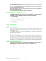
7.2.1 Open the device
After installing boot driver correctly, the V4L2-Like driver will also register video
devices in Host Linux system as shown in below. User could open the video devices
with the open function.
In DSPC-8662, there are 16 video devices registered for one chip, but only first two
video devices were available.
#ls -al /dev/video*
crw-rw----+ 1 root video 81, 0 2012-03-13 08:06 /dev/video0
crw-rw----+ 1 root video 81, 1 2012-03-13 08:06 /dev/video1
...
crw-rw----+ 1 root video 81, 15 2012-03-13 08:06 /dev/video15
7.2.2 Properties Negotiation
As normal V4L2 video device, it°Øs necessary to negotiate the possible values of
some properties. The properties to set on V4L2-Like device driver are:
Pixel Format
Image Size
Request Buffers and Query Buffer
DSPC-8661/8662-PCXE User Manual
24
The pixel format is how every pixel is stored in memory, and the application need to
know this format to allow the properly interpretation of that pixel and how big the
memory space is. In V4L2-Like device driver, there are compression formats exist,
H264 and MJPEG, as described in section 6.2.1.
User could follow this sample code to setup the
fmt.fmt.pix.pixelformat = V4L2_PIX_FMT_TI_H264;
if (-1 == xioctl (*fd, VIDIOC_S_FMT, &fmt))
errno_exit
("\nError:
pixel
format
ported\n");
not
sup-
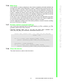
7.2.4 Request Buffers and Query Buffer Using Memory mapping
This is the fastest method, read and write functions are not needed, instead of those,
the mmap() function is used. This functions returns a pointer to the start of a valid
memory area, this memory is used by the application to read the data. A device support this method when the flag V4L2_CAP_STREAMING of the capabilities field in
the v4l2_capability struct is set.
A device supports this method if the field V4L2_CAP_STREAMING in the member
capabilities of the struct V4l2_capability returned by the VIDIOC_QUERYCAP ioctl is
set. If the particular user pointer method (not only memory mapping) is supported
must be determined by calling the VIDIOC_REQBUFS ioctl.
struct v4l2_requestbuffers req;
req.count
= 2;
req.type
= V4L2_BUF_TYPE_VIDEO_CAPTURE;
req.memory
= V4L2_MEMORY_MMAP;
if (-1 == xioctl (*fd, VIDIOC_REQBUFS, &req))
{
if (EINVAL == errno)
{
fprintf (stderr, "%s does not support "
"memory
mapping\n",
dev_name);
exit (EXIT_FAILURE);
} else {
errno_exit ("VIDIOC_REQBUFS");
}
}
25
DSPC-8661/8662-PCXE User Manual
Video For Linux 2 Sample Code
struct v4l2_format fmt;
CLEAR (fmt);
//set pixel format properties
fmt.type
= V4L2_BUF_TYPE_VIDEO_CAPTURE;
fmt.fmt.pix.width= width;
fmt.fmt.pix.height= height;
Chapter 7
7.2.3 Pixel Format and Image Size Negotiation.
This method combines the advantage of the both previous methods. In the user
pointer method buffers are allocated by the application and can be shared memory
(mmap) or virtual. Only pointers to data are exchanged, these pointers is passed in
struct v4l2_buffer. The driver must be switched into user pointer I/O mode by calling
the VIDIOC_REQBUFS with the desired buffer type.
The example code here show how to memory map one of requested buffers.
{
struct v4l2_buffer buf;
CLEAR (buf);
buf.type
buf.memory
buf.index
= V4L2_BUF_TYPE_VIDEO_CAPTURE;
= V4L2_MEMORY_MMAP;
= i;
if (-1 == xioctl (*fd, VIDIOC_QUERYBUF, &buf))
errno_exit ("VIDIOC_QUERYBUF");
buffers[i].length = buf.length;
buffers[i].start = mmap (NULL /* start anywhere */,
buf.length,
PROT_READ | PROT_WRITE /* required
*/,
MAP_SHARED /* recommended */,
*fd, buf.m.offset);
if (MAP_FAILED == buffers[i].start)
errno_exit ("mmap");
}
7.2.5 Getting audio data
Audio data was transfer in packet format described in section 6.4. User application
could get the audio data while mapping frame buffer into user memory space. Following example shows how to read audio packet with shifted pointer.
void *aud_ptr = &vid_ptr[PKT_QUE_AUD_OFT];
audpkt_t *audpkt = (audpkt_t *) aud_ptr;
len = audpkt->len;// available data length
src = &aud_ptr[sizeof(audpkt_t)];
//writing to standard output
ret = file_write_frames(src, len, ch, audf[ch]);
audpkt->len = 0;// Clear packet length
DSPC-8661/8662-PCXE User Manual
26
7.2.7 Private control command settings
User could setup extended features through VIDIOC_G_CTRL or VIDIOC_S_CTRL
operation code of V4L2 driver ioctl API.
Following example show how to set and get extra video standard from
V4L2_CID_VID_DIM_STD command, mentioned in section 6.2.2.
struct v4l2_control std= {.id = V4L2_CID_VID_DIM_STD,
.value = 0};
if (-1 == ioctl (*fd, VIDIOC_G_CTRL, &std))
perror ("VIDIOC_G_CTRL::V4L2_CID_VID_DIM_STD");
std.value = video_standard;
if (-1 == ioctl (*fd, VIDIOC_S_CTRL, &std))
perror ("VIDIOC_S_CTRL::V4L2_CID_VID_DIM_STD");
7.2.8 Close the device.
The close function is used to close the device.
27
DSPC-8661/8662-PCXE User Manual
Video For Linux 2 Sample Code
If user pointer or memory mapping is used, that are streaming oriented methods, the
first step is the start of the transmission of data. In addition these methods have buffers with queues, in that way, V4L2 enqueue data, and the application dequeue the
data, with a FIFO criteria. In the case of output devices, the process is the same but
inverse. In addition the buffer must be previously configured with the properties of the
frames, to know the size of one frame, for allocation of memory. And at the end of the
loop, the data transmission must be stopped and the buffers freed.
In the case of use of read/write functions in the main loop, the application only have
one memory buffer, that one allows the store of one frame. On a capture application
in every loop the read function must be called to capture one frame.
For the 3 methods is valid the use of the select() function, to wait for events, avoiding
the use of CPU when is waiting.
Chapter 7
7.2.6 Main loop
www.advantech.com
Please verify specifications before quoting. This guide is intended for reference
purposes only.
All product specifications are subject to change without notice.
No part of this publication may be reproduced in any form or by any means,
electronic, photocopying, recording or otherwise, without prior written permission of the publisher.
All brand and product names are trademarks or registered trademarks of their
respective companies.
© Advantech Co., Ltd. 2012