1
User’s manual CAST FOR OVERVIEW P SERIES DOC-3179-2 DOC-3179-2 Title: CAST – User Manual ID No.: DOC-3179-2 Date: 2006-12 Revision: 07 Chapter 1 Chapter 2 Chapter 3 Chapter 4 Chapter 5 Chapter 6 Chapter 7 Chapter 8 Chapter 9 Chapter 10 Chapter 11 Chapter 12 Chapter 13 Chapter 14 Chapter 15 Chapter 16 Primary Edition new new new new new new new new new new new new new new new new Update new: The corresponding chapters were newly generated or completely revised. corr.: Parts of the corresponding chapter were corrected; see edit mark. add: Missing parts of the corresponding chapter were added; see edit mark. Document History Changes resulting in a new version are marked with a bar in the margin of the text. Do not discard this page! This manual refers to CAST Release 2.2. CAST Release 2.2. supports the spectrometer of type USB4000. CAST Release 2.1 and CAST Release 2.2 have basically no changes compared to CAST Release 2.0. CAST Release 2.0 has only minor changes compared to rel. 1.2. New in this release: the database stores only one wall file. This makes the exchange of wall files easier. Main software changes of Release 1.2 compared to CAST Rel. 1.1: • Backup of color adjustment (luminance and coefficients) of the projectors • Color adjustment without spectrometer • More precise luminance slider • Proprietary test pattern • User targets with auto-saturation and auto-luminance • User defined cabling order Trademarks Company and product names listed in this manual are trademarks and/or registered trademarks of their respective owners. All of the company and product names listed in this publication serve as reference or example and are not intended as advertisement for these products or manufacturers. Copyright 2001-2006 Barco Control Rooms GmbH Die Weitergabe sowie die Vervielfältigung aller Unterlagen, die von uns überlassen werden, deren Verwertung und Mitteilung ihres Inhaltes an Dritte ist nicht gestattet, soweit dies nicht ausdrücklich zugestanden ist. Urheberrechte, insbesondere auch solche an Software, werden nur insoweit übertragen, als es für die Erreichung des speziellen Vertragszwecks erforderlich ist. Zuwiderhandlungen können zu Schadensersatz verpflichten. Alle Rechte aus der Erteilung eines Patents oder der Eintragung eines Gebrauchsmusters verbleiben bei uns. Copyright 2001-2006 Barco Control Rooms GmbH All rights reserved. No part of this document may be copied, reproduced or translated. It shall not otherwise be recorded, transmitted or stored in a retrieval system without the prior written consent of the Barco Control Rooms GmbH. Warranty and Compensation for Damages The company Barco Control Rooms GmbH guarantees perfect manufacture within the scope of legal warranty periods. The buyer has to inspect the goods delivered by Barco Control Rooms GmbH for transport, material, or manufacturing damages/defects immediately upon receiving the goods. Any complaints have to be immediately submitted to Barco Control Rooms GmbH in writing. The warranty period starts with at time of risk transference and with initial operation for special systems and software but not later than 30 days after the time of risk transference. If the complaints are justified Barco Control Rooms GmbH can chose to repair or replace the goods within an appropriate timeframe. If repairs are not possible or if they failed the buyer can demand a price reduction or withdraw from the contract (cancellation). Barco Control Rooms GmbH is not liable for any additional demands, especially for direct or indirect damages as well as damages caused by operating the software or other services, system-integral or independent, provided by Barco Control Rooms GmbH, if it cannot be proven that the damage is caused or based on missing properties guaranteed in writing or that Barco Control Rooms GmbH is guilty of gross negligence or intend of defrauding the buyer. If the buyer or a third party changes, modifies, repairs, or improperly operates or uses the goods delivered by Barco Control Rooms GmbH, especially if systems are started or operated incorrectly or if goods are subjected to risks after the transfer of risk, which are not covered by the contract, the buyer's warranty claims become null and void. System failures caused by programs or special electronics supplied by the customer, e.g., interfaces, are also not covered by the warranty. Normal wear and tear as well as normal maintenance is not covered by the Barco Control Rooms GmbH warranty. The environmental conditions specified in this manual as well as the care and maintenance guidelines have to be adhered to by the customer. Corrections To • Barco Control Rooms GmbH An der Rossweid 5, D-76229 Karlsruhe Telephon: (49) (721) 6201-0, Fax: (49) (721) 6201-298 E-mail [email protected], Web www.barcocontrolrooms.de Sender: Date: Please correct the following items in the documentation DOC-3179-2: Page Incorrect Text Correction Contents 1 Preliminary Remarks ......................................................................................................................... 1-1 1.1 Overview......................................................................................................................................................1-2 1.2 Manual Structure .........................................................................................................................................1-2 1.3 Numbering...................................................................................................................................................1-3 1.4 Styles and Symbols......................................................................................................................................1-3 2 CAST – a tool for Color Adjustment.................................................................................................... 2-1 2.1 Introduction .................................................................................................................................................2-2 2.2 Automatic Color Adjustment by CAST .........................................................................................................2-2 2.3 Limitations of automatic color adjustment ................................................................................................2-2 2.4 Visual evaluation optimizes automatic adjusting ......................................................................................2-2 3 Installation and Cabling..................................................................................................................... 3-1 3.1 Requirements ..............................................................................................................................................3-2 3.2 Components of CAST....................................................................................................................................3-2 3.3 Setup ............................................................................................................................................................3-3 3.4 Update of previous releases of CAST ............................................................ .........................................3-4 3.5 Spectroscope USB 2000...............................................................................................................................3-5 . 3.6 Installation of the spectroscope USB4000 (new).......................................................................................3-9 . 3.7 Installation of the cordless mouse........................................................................................................... 3-13 3.8 Remote Control Cabling............................................................................................................................ 3-14 3.9 Sequence of communication ................................................................................................................... 3-15 4 Color Measurement and Color Adjustment....................................................................................... 4-1 4.1 Color .............................................................................................................................................................4-2 4.2 White point, hue, and saturation................................................................................................................4-3 4.3 Principle of Color Adjustment .....................................................................................................................4-4 4.4 CAST – mode of operation ...........................................................................................................................4-5 4.4.1 Operating conditions of CAST .............................................................................................................4-5 4.4.2 Colors...................................................................................................................................................4-5 4.4.3 Brightness ........................................................................................................................................ 4-11 5 Overview of adjustment steps .......................................................................................................... 5-1 5.1 Flow chart ....................................................................................................................................................5-2 5.2 CAST – options of operation ........................................................................................................................5-3 5.2.1 Recommended standard procedure: bold .........................................................................................5-3 5.2.2 Skip second measuring cycle: dotted ................................................................................................5-3 5.2.3 Modify target: dash ............................................................................................................................5-3 5.2.4 Without any spectrometer: dash-dot-dash........................................................................................5-3 5.2.5 Adjustment of individual projection modules only...........................................................................5-3 5.3 List of important topics ...............................................................................................................................5-4 6 Fully automated adjustment of the Display Wall ............................................................................. 6-1 6.1 Starting the software ..................................................................................................................................6-2 6.2 Configuration of measurement...................................................................................................................6-4 6.3 Connecting the Display Wall .......................................................................................................................6-6 6.4 Loading the Factory Colors ....................................................................................................................... 6-10 6.5 Measuring the factory color locations ..................................................................................................... 6-11 6.6 Auto Target ............................................................................................................................................... 6-12 6.7 Verifying the Auto-target ......................................................................................................................... 6-14 7 User-defined targets.......................................................................................................................... 7-1 7.1 General.........................................................................................................................................................7-2 7.1.1 Modifying the white point .................................................................................................................7-4 7.1.2 Modifying the color locations for the primaries................................................................................7-6 7.1.3 Modification of luminance..................................................................................................................7-8 7.2 Activating the modified target ...................................................................................................................7-9 7.2.1 Verifying the new target ................................................................................................................. 7-10 7.2.2 Modifying a user-defined target ..................................................................................................... 7-10 8 Reachability ....................................................................................................................................... 8-1 8.1 General.........................................................................................................................................................8-2 8.2 Not reachable: luminance ...........................................................................................................................8-2 8.3 Not reachable: color ....................................................................................................................................8-4 8.4 Not reachable: Gradient between the stripes is too big ...........................................................................8-6 8.4.1 Not reachable: Indication on the measurement dialog....................................................................8-7 8.4.2 Not reachable: What to do .................................................................................................................8-7 9 Maintenance with CAST ..................................................................................................................... 9-1 9.1 General.........................................................................................................................................................9-2 9.2 Projector Exchange ......................................................................................................................................9-2 9.3 Lamp exchange ...........................................................................................................................................9-3 9.4 Lamp ageing ................................................................................................................................................9-4 9.5 Maintenance without spectrometer ...........................................................................................................9-4 10 Manual Adjustment ....................................................................................................................... 10-1 10.1 General.................................................................................................................................................... 10-2 10.2 Fine tuning after the automated adjustment procedure ..................................................................... 10-2 10.2.1 Manual Adjustment: White ........................................................................................................... 10-4 10.2.2 Manual Adjustment: Luminance ................................................................................................... 10-5 10.2.3 Manual Adjustment: primary colors.............................................................................................. 10-7 10.2.4 Manual Adjustment: individual adjustment of the 8 stripes ....................................................... 10-9 10.3 Fully manual wall adjustment ............................................................................................................. 10-10 10.3.1 Manual adjustment from scratch................................................................................................ 10-11 10.3.2 Improve homogeneity of an already adjusted Display Wall ..................................................... 10-12 11 Advanced Topics ............................................................................................................................ 11-1 11.1 PSI Settings ............................................................................................................................................. 11-2 11.1.1 Backup user settings ..................................................................................................................... 11-2 11.1.2 Restore factory settings ................................................................................................................ 11-2 11.1.3 Exchange of X-Cube....................................................................................................................... 11-3 11.1.4 Restore user settings..................................................................................................................... 11-3 11.1.5 Saving and restoring PSI settings ................................................................................................. 11-4 11.2 Measuring the projectors' drift .............................................................................................................. 11-5 11.3 Disable Module....................................................................................................................................... 11-6 11.4 Vertical inhomogeneity.......................................................................................................................... 11-7 11.4.1 Choosing the vertical measuring position .................................................................................... 11-9 11.5 Horizontal inhomogeneity ................................................................................................................... 11-10 11.5.1 Color and Luminance ................................................................................................................... 11-10 11.5.2 Basics of CAST alogrithmic........................................................................................................... 11-11 11.5.3 Gradient limitation error (GLE).................................................................................................... 11-11 11.5.4 Maximal allowed gradients......................................................................................................... 11-12 11.6 Adjusting Projectors with extremely bad color locations................................................................... 11-14 12 CAST user interface ........................................................................................................................ 12-1 12.1 Menu bar of CAST ................................................................................................................................... 12-2 12.2 File menu ................................................................................................................................................ 12-2 12.2.1 New................................................................................................................................................ 12-2 12.2.2 Open............................................................................................................................................... 12-4 12.2.3 Close ............................................................................................................................................... 12-5 12.2.4 Delete wall..................................................................................................................................... 12-5 12.2.5 Exit.................................................................................................................................................. 12-6 12.3 Wall ......................................................................................................................................................... 12-6 12.3.1 PSI settings .................................................................................................................................... 12-7 12.3.1.1 Backup user settings ....................................................................................................................... 12-7 12.3.1.2 Restore factory settings .................................................................................................................. 12-7 12.3.1.3 Restore user settings....................................................................................................................... 12-7 12.3.2 Color adjustment ........................................................................................................................... 12-8 12.3.2.1 Load.................................................................................................................................................. 12-8 12.3.2.2 Save to EEPROM............................................................................................................................... 12-8 12.3.2.3 Reduce luminance of rows.............................................................................................................. 12-9 12.3.2.4 Recalculate auto target ................................................................................................................... 12-9 12.3.3 Measure ....................................................................................................................................... 12-10 12.3.4 Wall properties............................................................................................................................. 12-11 12.4 Projector................................................................................................................................................ 12-12 12.4.1 PSI settings .................................................................................................................................. 12-12 12.4.2 Lamp exchange............................................................................................................................ 12-12 12.4.3 Disable Module ............................................................................................................................ 12-13 12.4.4 Measure ....................................................................................................................................... 12-13 12.4.5 Manual adjust .............................................................................................................................. 12-13 12.4.6 Color&Luminance ......................................................................................................................... 12-14 12.4.6.1 Colors.............................................................................................................................................. 12-14 12.4.6.2 Luminance...................................................................................................................................... 12-18 12.4.6.3 Distance to target .......................................................................................................................... 12-20 12.4.6.4 Reachability ................................................................................................................................... 12-21 12.5 Tools ...................................................................................................................................................... 12-22 12.5.1 Options ......................................................................................................................................... 12-22 12.5.1.1 File locations .................................................................................................................................. 12-22 12.5.1.2 Hardware ....................................................................................................................................... 12-23 12.5.1.3 Remote mouse .............................................................................................................................. 12-24 12.5.1.4 Tolerances ...................................................................................................................................... 12-25 12.5.1.5 Advanced ....................................................................................................................................... 12-26 12.5.1.6 How CAST determines the Auto target......................................................................................... 12-27 12.5.2 Calibrate Spectrometer................................................................................................................ 12-30 12.5.3 Test spectrometer........................................................................................................................ 12-32 12.6 Help....................................................................................................................................................... 12-32 12.6.1 Contents ....................................................................................................................................... 12-33 12.6.2 Select language ........................................................................................................................... 12-33 12.6.3 About............................................................................................................................................ 12-33 12.7 Tool bar ................................................................................................................................................. 12-34 12.7.1 New wall...................................................................................................................................... 12-34 12.7.2 Open wall..................................................................................................................................... 12-34 12.7.3 Connect ........................................................................................................................................ 12-34 12.7.4 Module Order ............................................................................................................................... 12-35 12.7.5 Projector Identification ................................................................................................................ 12-36 12.7.6 Grid view...................................................................................................................................... 12-36 12.7.7 Table view.................................................................................................................................... 12-37 12.7.8 Factory Colors............................................................................................................................... 12-38 12.7.8.1 Grid view........................................................................................................................................ 12-38 12.7.8.2 Table view...................................................................................................................................... 12-38 12.7.9 Adjusted color .............................................................................................................................. 12-40 12.7.9.1 Grid view........................................................................................................................................ 12-40 12.7.9.2 Table view...................................................................................................................................... 12-41 12.7.9.3 Test pattern.................................................................................................................................... 12-42 13 Theoretical Principles..................................................................................................................... 13-1 13.1 Introduction ............................................................................................................................................ 13-2 13.2 Color ........................................................................................................................................................ 13-2 13.3 Color differences..................................................................................................................................... 13-3 13.4 Spectral sensitivity of the human eye................................................................................................... 13-4 13.5 Imaging Devices ..................................................................................................................................... 13-4 13.6 Color Adjustment Theory........................................................................................................................ 13-7 13.6.1 Primary color Correction................................................................................................................ 13-7 13.6.2 White Correction ............................................................................................................................ 13-7 13.6.3 Brightness Correction..................................................................................................................... 13-7 13.6.4 Uniformity Correction .................................................................................................................... 13-7 13.7 How CAST Works..................................................................................................................................... 13-8 13.7.1 Principle ......................................................................................................................................... 13-8 13.7.2 Factory Colors................................................................................................................................. 13-9 13.7.3 Measurement procedure............................................................................................................. 13-10 13.7.3.1 User targets.................................................................................................................................... 13-10 14 Technical Data................................................................................................................................ 14-1 14.1 Technical data of the CAST spectroscope .............................................................................................. 14-2 14.2 Technical data of the cordless mouse ................................................................................................... 14-2 15 Troubleshooting ............................................................................................................................. 15-1 15.1 Troubles .................................................................................................................................................. 15-2 16 Hotline............................................................................................................................................ 16-1 16.1 Addresses................................................................................................................................................ 16-2 Index...........................................................................................................................................................I 1. Preliminary Remarks 1 Preliminary Remarks Barco – CAST for OverView P series – Doc-3179-2 – user's manual – Revision 07 – December-2006 _____________________________________ 1-1 1. Preliminary Remarks 1.1 Overview This chapter explains the structure of the manual as well as the applied style conventions and symbols. 1.2 Manual Structure This manual is divided into 16 chapters: Preliminary Remarks This chapter explains the structure of the manual itself as well as the applied style conventions and symbols. CAST – a tool for Color Adjustment This chapter explains why projection modules have to be adjusted and introduces CAST Installation and Cabling Explains the system requirements and the installation of CAST, software, spectroscope, mouse and the remotecontrol cabling Color Measurement and Color Adjustment Gives some background information on color measurement and explains how CAST works. Overview of adjustment steps Shows a flow chart of the adjustment procedure and a list which refers to the most important topcis in the manual Fully automated adjustment of a Display Wall Gives a detailed description of the various steps CAST performs during an adjustment procedure User-defined targets Explains how the target of CAST can be customized to meet special requirements or to deal with projectors of lower quality Reachability This chapter deals with the main reasons a projector cannot reach the target Maintenance with CAST Describes how to preserve or re-new the adjustment of a Display Wall Manual Adjustment Introduces into the adjustment procedure without spectrometer Advanced Topics Gives some background information on projectors and on the way CAST works and points out how to modify the measurement strategy to optimize adjustment depending on the current conditions CAST user interface This chapter is a reference to the GUI and explains the menus and dialogs Theoretical Principles Goes into detail with respect to the color correction as implemented in digital poly-Silicon projection engines Technical Data Includes the technical specification of the CAST hardware spectrometer and cordless mouse Trouble shooting Lists possible problems and their solution Barco – CAST for OverView P series – Doc-3179-2 – user's manual – Revision 07 – December-2006 _____________________________________ 1-2 1. Preliminary Remarks Hotline Lists the contact addresses in case you encounter problems 1.3 Numbering Chapters, pages, illustrations, and tables are numbered separately. The chapters and the chapter sections feature a »point syntax«, e.g., 4.2.3; however, pages feature a »line syntax« 1.4 Styles and Symbols The typographic styles and the symbols used in this document have the following meaning: Bold Labels, menus and buttons are printed in Bold font. Condensed Links to both other chapters of this manual and to sites in the Internet are printed condensed. In the on-line version of this manual all hyperlinks appear teal. Courier Names of files and parts from programs are printed in the Courier font. Courier bold Inputs you are supposed to do from the keyboard are printed in Courier bold font. The sheet icon indicates additional notes. Next to this icon you find further information. This icon marks tips. Next to this icon you find important notes. Barco – CAST for OverView P series – Doc-3179-2 – user's manual – Revision 07 – December-2006 _____________________________________ 1-3 2. CAST – a tool for Color Adjustment 2 CAST – a tool for Color Adjustment Barco – CAST for OverView P series – Doc-3179-2 – user's manual – Revision 07 – December-2006 _____________________________________ 2-1 2. CAST – a tool for Color Adjustment 2.1 Introduction As known from computer monitors and TV, every device has its specific color rendering. In case this color rendering does not meet your needs, you adjust the colors until the results pleases you. Usually this is done once, and should be valid for all applications or all broadcasting, respectively. In case of a single monitor, color adjustment is quite an easy task. In case of multiple monitors which should look the same, this task is difficult: Due to production processes, the desired color rendering as set on one monitor might not be achieved by the other monitors. 2.2 Automatic Color Adjustment by CAST Due to tolerances, modular rear-projection Display Walls don't feature a homogenous color and brightness distribution: every projection module houses its own projection engine with its individual color rendering. CAST is a software with a measuring device which measures the factory colors of every projector. Subsequently it determines a color space which can be reached by every projection engine, and then adjusts every projection engine to this common color space. As a result the Display Wall features homogenous color and brightness. 2.3 Limitations of automatic color adjustment In spite of being a measurable property, color is an impression of a physiological sense and perceived differently by different observers, above all when looked at under different viewing angles. Therefore an observer might judge the result of the automatic color adjustment by CAST to be unsatisfying. CAST works on a formal objective basis. Human color perception is a highly subjective matter. 2.4 Visual evaluation optimizes automatic adjusting To overcome the above mentioned limitations, CAST offers in addition the possibility of a manual adjustment. After an automatic color adjustment, a visual fine tuning can be done. Barco – CAST for OverView P series – Doc-3179-2 – user's manual – Revision 07 – December-2006 _____________________________________ 2-2 3. Installation and Cabling 3 Installation and Cabling Barco – CAST for OverView P series – Doc-3179-2 – user's manual – Revision 07 – December-2006 _____________________________________ 3-1 3. Installation and Cabling 3.1 Requirements • Windows 2000 or Windows XP • Standard PC or Laptop • Processor Pentium II 500 MHz or higher • Main memory 64 MB • Screen resolution XGA (1024×768) or higher • Interfaces: 1x USB (spectroscope) 1x USB (cordless mouse) 1x Serial (remote control) 3.2 Components of CAST CAST consists of a color measuring unit (spectrometer) [2] connected with a notebook computer via a USB interface [3], and a cordless mouse[4] with its receiver [5] to control the measurement. During measurement, the sensor [S] of the spectrometer has to touch the screen. The CAST software [1] controls the measuring instrument, processes the measured data, and adjusts the projectors via remote control. For remote control cabling , the delivery of CAST includes the connection between the laptop and the first projection engine (V24 cable [6] and adapter [7] as well as the shorting plug [8] to be plugged into the remote-out socket of the last projection engine. Figure 3-1 CAST Installation therefore comprises installation of software (CAST software) and hardware (spectrometer, cordless mouse) Barco – CAST for OverView P series – Doc-3179-2 – user's manual – Revision 07 – December-2006 _____________________________________ 3-2 3. Installation and Cabling 3.3 Setup You need administrative access rights to install CAST. Enter the CD into the computer drive and run setup.exe. The Install Shield Wizard will guide you through the installation process. Follow the displayed instructions. Figure 3-2 InstallShield Wizard The installation procedure offers a complete and a custom installation: Figure 3-3 InstallShield Wizard Select (1) Complete to install the CAST software, both versions for OverView D series and OverVierw P series as well as the spectrometer ActiveX control. Select (2) Custom to install only one of the software versions or the spectrometer ActiveX control only.. Barco – CAST for OverView P series – Doc-3179-2 – user's manual – Revision 07 – December-2006 _____________________________________ 3-3 3. Installation and Cabling A folder named Barco CAST is created during the installation in the directory Program Files and shortcuts are generated as well. The following subfolders are created as well: Cast_P (complete installation or selected component with custom installation) with the subfolders Help, PSI-Backup-Settings, PSI-Factory-Settings, Template DB as well as the examples database. Help In this subfolders the help file and the manual is located TemplateDB In this subfolder an Access database named template.mdb is created . This database is prepared for the projector data, but initially contains no data. PSI-Factory-Settings It is recommended to save the PSI factory settings from the CAST CD-ROM to this folder. PSI-Backup-Settings For each wall, when restoring user settings, CAST will automatically create an appropriate subfolder to the PSI-Backup-Settings folder to save the user settings. In Tools | Options | File locations, cf. File locations¸ CAST refers to these folders. If you choose to have different folders for the PSI factory settings and PSI user settings, you have to adjust the entries on this tab accordingly! Examples There you can find some samples databases. Cast_D (complete installation or selected component with custom installation) with the subfolders Help, Examples, Template DB. Help In this subfolders the help file and the manual is located TemplateDB In this subfolder an Access database named template.mdb is created . This database is prepared for the projector data, but initially contains no data. Examples There you can find some sample databases. Inf This is the subfolder for the driver files of the CAST spectroscopes If CAST propose to restart the system, follow this advice! After re-booting, log in again with administrative rights to make sure that Windows 2000 can perform the update of the configuration files. If this update is done, no longer administrative rights are required for CAST. 3.4 Update of previous releases of CAST To update previous releases of CAST, you have to de-install the software and then to install the new release. You need administrative privileges to de-install and re-install the software! The database files of previous versions of CAST 2.0 (β versions) are not compatible! CAST Rel. 2.2 still supports the spectroscope USB2000. It is recommended to update the driver, cf. Spectroscope USB2000. Barco – CAST for OverView P series – Doc-3179-2 – user's manual – Revision 07 – December-2006 _____________________________________ 3-4 3. Installation and Cabling 3.5 Spectroscope USB2000 Check the label on the spectroscope: if it reads CST-3122-01, then the spectroscope is of type USB2000. With previous deliveries of CAST, a spectroscope of type USB2000 has been included. When updating the CAST software to rel. 2.2, it is recommended to update the driver of this spectroscope as well. In case the spectroscope USB2000 shows a strange behavior, update of the driver file is mandatory! During the installation of the CAST software the driver files of the spectroscope have been copied to C:\windows\inf. To update the driver, navigate to the entry of the spectroscope in the Windows Device Manager: Figure 3-4 The spectroscope (Ocean Optics USB2000) is listed in the Device Manager Right click on the entry of spectroscope. From the context menu, select Properties, and then activate the tab Driver. Click the button Update driver. Select the file ooi_usb.inf, located in C:\Windows\Inf Barco – CAST for OverView P series – Doc-3179-2 – user's manual – Revision 07 – December-2006 _____________________________________ 3-5 3. Installation and Cabling Figure 3-5 Driver file for the spectroscope This driver supports the spectroscope USB2000 as well as the spectroscope USB4000. However, with USB4000, in addition Java Runtime Environment has to be installed! (For USB2000, no JRE is required!) After the update of the driver, the spectroscope USB2000 gets a dedicated entry in the Windows Device Manager. It is no longer listed below the Universal Serial Bus controllers: Barco – CAST for OverView P series – Doc-3179-2 – user's manual – Revision 07 – December-2006 _____________________________________ 3-6 3. Installation and Cabling In addition to the driver files, CAST requires a calibration file, which is specific for every CAST spectroscope. When the spectroscope is connected, CAST determines its serial number and requests for the corresponding calibration file. Starting measurements without the calibration file results in the message: Figure 3-6 The calibration file is missing! If the calibration file is missing, this message also pops up when switching to the Hardware tab in Tools | Options. Every CAST spectroscope includes a calibration file. It is recommended to store this file in a safe location since it is needed again when re-installing the CAST spectroscope. If this message is ignored and CAST is started without the necessary calibration file of the CAST spectroscope no measurements will be taken by CAST. On the Hardware tab this status is notified. The serial number of the CAST spectroscope then is written in red. Barco – CAST for OverView P series – Doc-3179-2 – user's manual – Revision 07 – December-2006 _____________________________________ 3-7 3. Installation and Cabling Figure 3-7 spectrometer status is OK In regular intervals (about one year) the CAST spectroscope has to be re-calibrated in the factory, cf. Hardware. Recalibration results in a new calibration file. Before operating the CAST spectroscope, it is recommended to do a luminance calibration (cf. Calibrate Spectrometer). CAST is able to manage multiple CAST spectroscopes and their corresponding calibration files. The serial numbers of the spectroscope are read and the calibration files requested if they are not available yet. All calibration files, which have been used with CAST systems, are saved in the WinNT folder in the file spectroscope.ini. If the USB interface is plugged into the laptop and not recognized when booting the laptop, unplug it, and plug it in again. It then should be recognized! Barco – CAST for OverView P series – Doc-3179-2 – user's manual – Revision 07 – December-2006 _____________________________________ 3-8 3. Installation and Cabling 3.6 Installation of the spectroscope USB4000 (new) Check the label on the spectroscope: if it reads CST-3122-11, then the spectroscope is of type USB4000. The spectroscope USB4000 requires JRE 1.4 or 1.5 or JRE 6! On the CAST CD-ROM, JRE1.5 is provided in the folder: …\Accessories\Java Runtime Environment. In case there are multiple JRE installed on a computer, make sure that JRE current version points to JRE 1.4 or 1.5 or 1.6: To check the respective registry key, select Start|RUN|Regedit Navigate to HKEY_LOCAL_MACHINE\SOFTWARE\JavaSoft\Java Runtime Environment\CurrentVersion If CurrentVersion is different from 1.4 or 1.5 or 1.6, modify the key! The CAST spectroscope has an USB interface and is being installed via Plug&Play. The following dialog is displayed when you plug in the spectroscope: Figure 3-8 Plug&Play: Found New Hardware During the installation of the CAST software the driver files for the spectrosopes have been copied to the folder …\Windows and ….\Windows\INF. No more actions to activate/enable the drivers are required. After the successful installation, the Windows Device Manager includes a new nod Ocean Optics Devices and lists CAST spectroscope as a new hardware device: Barco – CAST for OverView P series – Doc-3179-2 – user's manual – Revision 07 – December-2006 _____________________________________ 3-9 3. Installation and Cabling Figure 3-9 The spectroscope (Ocean Optics USB4000) is listed in the Device Manager In case you encounter problems with your spectroscope, navigate to the respective entry in the device manager and right-click on the device to check its properties and/or to update the driver. For location of the driver files, see above. In addition to the driver files, CAST requires a calibration file, which is specific for every CAST spectroscope. When the spectroscope is connected, CAST determines its serial number and requests for the corresponding calibration file. Starting measurements without the calibration file results in the message: Figure 3-10 The calibration file is missing! If the calibration file is missing, this message also pops up when switching to the Hardware tab in Tools | Options. Every CAST spectroscope includes a calibration file. It is recommended to store this file in a safe location since it is needed again when re-installing the CAST spectroscope. If this message is ignored and CAST is started without the necessary calibration file of the CAST spectroscope no measurements will be taken by CAST. On the Hardware tab this status is notified. The serial number of the CAST spectroscope then is written in red. Barco – CAST for OverView P series – Doc-3179-2 – user's manual – Revision 07 – December-2006 ____________________________________ 3-10 3. Installation and Cabling Figure 3-11 spectrometer status is not OK In regular intervals (about one year) the CAST spectroscope has to be re-calibrated in the factory, cf. Hardware. Recalibration results in a new calibration file. Before operating the CAST spectroscope, it is recommended to do a luminance calibration (cf. Calibrate Spectrometer). CAST is able to manage multiple CAST spectroscopes and their corresponding calibration files. The serial numbers of the spectroscope are read and the calibration files requested if they are not available yet. All calibration files, which have been used with CAST systems, are saved in the WinNT folder in the file spectroscope.ini. If the USB interface is plugged into the laptop and not recognized when booting the laptop, unplug it, and plug it in again. It then should be recognized! Barco – CAST for OverView P series – Doc-3179-2 – user's manual – Revision 07 – December-2006 ____________________________________ 3-11 3. Installation and Cabling 3.7 Use of miscellaneous spectrometers When using miscellaneous spectrometers, e.g. USB2000 and USB4000, in one installation, you should keep in mind that the measurement values may differ. USB4000, for example, in principle measures colors which are more saturated. When adjusting replaced projection units to the target of a display wall, make sure to use the type of spectrometer which has been used to determine the target. In case you are not sure about the type of spectrometer, or in case this type of spectrometer is not available, re-measuring and re-adjustment of the entire display wall (including the new projection unit) is recommended! Barco – CAST for OverView P series – Doc-3179-2 – user's manual – Revision 07 – December-2006 ____________________________________ 3-12 3. Installation and Cabling 3.8 Installation of the cordless mouse CAST comes with a cordless mouse, the Ultra GT cordless optical mouse of Gyration. Its installation is quite easy; no driver files are required. The following installation instructions are copied from Gyration web page: Remove Protective Tab from Mouse The Ultra Mouse ships with a clear plastic sheet inserted beneath the battery pack. This keeps the battery from fully discharging before the product is sold. Remove the battery pack by depressing the button at the base of the mouse. Remove the plastic tab and discard. Replace the battery pack. Charge Mouse Batteries The rechargeable Ultra Mouse batteries may need to be recharged before first use. Fully depleted batteries require up to 9 hours of charge for full replenishment. To charge the mouse, simply plug the charging cradle into a standard electrical outlet and place the mouse in the cradle. The LED light on the charging cradle will light solid and the LED light on the top of the mouse will pulsate slowly. Note: The mouse does not require a full charge to operate and the batteries have no memory effect so charging it for longer or shorter times between uses will have no adverse effects. Plug in USB Receiver Turn on the computer and plug the USB receiver into an available USB port on your computer. The Ultra USB receiver will also work with USB hubs or USB extenders. Depending on your operating system, your computer may perform a brief USB Device Installation routine. If so, simply follow any on-screen instructions. Put USB Receiver into 'LEARN' Mode The LEARN button is located on the top of the USB receiver. Press the LEARN button for 2 seconds, then release. The receiver STATUS light will flash slowly indicating the receiver is now ready to be synchronized with the mouse. Synchronize Mouse The TEACH button is located on the bottom of the Ultra Mouse. Press the TEACH button and release. The STATUS light on the USB receiver will flicker for 5 seconds indicating the USB receiver has recognized and synchronized the mouse. Take the USB Receiver out of 'LEARN' Mode Press the LEARN button on the USB Receiver again for 2 seconds, then release. The receiver STATUS light will stop flashing, indicating the receiver is now in normal operating mode. This step is optional because the receiver will automatically return to Normal mode after 5 minutes. Doing so manually ensures that your receiver will not accidentally 'Learn' any other devices that may be in the vicinity. Barco – CAST for OverView P series – Doc-3179-2 – user's manual – Revision 07 – December-2006 ____________________________________ 3-13 3. Installation and Cabling 3.9 Remote Control Cabling Make sure that there is no SNMP agent running. Indicate the Display Wall as being unmanaged. Communication between CAST and the projection engines is done via the serial line. Before adjusting a Display Wall, the remote control cabling has to be done. For OverView P series, only use the combination cable/adapter included in the delivery of CAST. Do not connect the communication cable of OverView D series! CAST includes a V24 cable, an adapter and a shorting plug for the remote control cabling. The remote control cabling has to be done in the following way: • plug one interface of the provided adapter to one interface of the V24 cable (both included in CAST) • plug the second interface of the adapter into the serial interface of the computer • connect the second interface of the V24 cable to the remote-in socket of the first projection engine. • connect all other projection engines to the remote-control chain by connecting the remote-out socket of the previous engine to the remote-in socket of the following engine by means of the V24 cable included in the projection modules. • plug the shorting plug (included in CAST) into the remote-out socket of the last projection engine in order to close the ring. This kind of cabling is called daisy chain. The connection (V24 cable and adapter) between the serial interface of the laptop and the first projection engine as well as the shorting plug are included in the delivery of CAST The projection engines are addressed via an un-ambiguous address. The addresses are allocated in the sequence of the cabling. CAST addresses the projection engines using this address. A shorting plug must be inserted into the Remote Out socket of the last device in order to close the ring. Figure 3-12 remote-control cabling Barco – CAST for OverView P series – Doc-3179-2 – user's manual – Revision 07 – December-2006 ____________________________________ 3-14 3. Installation and Cabling For example the cabling of 2×2 system could look like this. Please note also the addresses. address 2 address 3 projection engine in remote out address 1 in in remote out address 4 projection engine remote projection engine out projection engine in remote out serial port RCM (Laptop) Figure 3-13 cabling of 2×2 configuration 3.10 Sequence of communication Figure 3-14 communication process Barco – CAST for OverView P series – Doc-3179-2 – user's manual – Revision 07 – December-2006 ____________________________________ 3-15 4. Color Measurement and Color Adjustment 4 Color Measurement and Color Adjustment Barco – CAST for OverView P series – Doc-3179-2 – user's manual – Revision 07 – December-2006 _____________________________________ 4-1 4. Color Measurement and Color Adjustment 4.1 Color Color is an impression of a physiological sense. By means of the "CIE 1976" chromaticity diagram color can be described by its coordinates. G R B Figure 4-1 CIE 1976 chromaticity diagram If three points in this diagram are selected and combined to a triangle every color within this triangle can be created by mixing the three colors placed at the corners. With display devices, usually Red, Green, and Blue are selected colors placed at the corner. These colors are called primaries. Barco – CAST for OverView P series – Doc-3179-2 – user's manual – Revision 07 – December-2006 _____________________________________ 4-2 4. Color Measurement and Color Adjustment 4.2 White point, hue, and saturation On the straight line defined by a color located on the outline of the triangle and the white point, the hue of this color remains the same, but the saturation decreases towards the white point. G W R B* B Figure 4-2 moving from B* to W, hue remains constant, saturation decreases Barco – CAST for OverView P series – Doc-3179-2 – user's manual – Revision 07 – December-2006 _____________________________________ 4-3 4. Color Measurement and Color Adjustment 4.3 Principle of Color Adjustment Due to production processes, imaging devices have native color deviations. In case of two imaging devices, the two color triangles might look like this: G1 G2 R1 B1 R2 B2 Figure 4-3 color triangles of two imaging devices (schematic) A Display Wall housing these imaging devices features rather inhomogeneous color and brightness. Therefore the projection engines have to be adjusted to a common color triangle. It is obvious that the common color triangle is the intersection of the individual color triangles. G1 G2 G* R* R1 R2 B* B1 B2 Figure 4-4 common color triangle Compared to the color locations before adjustment, the primary colors of the adjusted imaging devices are less saturated. Besides the luminance has decreased. Barco – CAST for OverView P series – Doc-3179-2 – user's manual – Revision 07 – December-2006 _____________________________________ 4-4 4. Color Measurement and Color Adjustment 4.4 CAST – mode of operation 4.4.1 Operating conditions of CAST For the color adjustment of optical engines which are used in rear projection modules measurements of the uncorrected primary colors are required. These measurements will be done in the field at the final installation under different ambient light conditions. Even if the rear projection principle is much less sensitive to the ambient light, the measured color coordinates might be wrong by the impact of the ambient light. Due to the laws of color mixing, red and blue are expected to suffer most under the spoiling effect of the background light Especially in blue, for a real precision measurement it is mandatory to dimm down the ambient light. To achieve an accuracy in u’, v’ of better than +- 0.001 when measuring on a 50" screen, it is recommended to ensure an outside illumination of the screen by less than 50 Lux. For larger screen sizes the upper limit becomes even smaller! The upper limit of the ambient light is calculated according the following rule: 50 upper limit = 50 Lux ∗ screensize 2 with screensize is the screen diagonal value (in inch) Please note that the upper limit might also depend on the stray element of the screen. During measurement, it is mandatory that the backside of the projection modules is closed by the backside sheetmetal shielding the CAST sensor is pressed tightly on the screen to avoid the direct detection of ambient light. 4.4.2 Colors As explained above, imaging devices feature native color deviations. Display Walls combine individual rear projection modules, each of them have its own imaging device. These imaging devices have to be adjusted to one common color location. For the convenient automatic color adjustment, Barco has developed CAST. CAST includes a spectrometer to measure the color locations of the projection engines as well as a software to determine a common color location and to adjust the projection engines to this common target. Color deviations do not only occur between different projection engines. They also occur within one single imaging device. A projection engine is divided into 8 stripes: Barco – CAST for OverView P series – Doc-3179-2 – user's manual – Revision 07 – December-2006 _____________________________________ 4-5 4. Color Measurement and Color Adjustment 12 3 4 5 6 7 8 Figure 4-5 a projector is divided into 8 stripes CAST measures the left stripe (1), the center of the two middle stripes (4 and 5), and the right stripe(8). The measurement sequence is white, red, green, blue. Thus per projection module 3 locations for R, G, and B are determined as well as 3 positions for the white point. The result of this measurement is visualized on the Color tab of the Projector|Color&Luminance dialog. Figure 4-6 color triangles of the three stripes measured by CAST If you zoom in the graphic (right mouse click), you can distinguish the three measurement points for white and the primaries. You can also use the zoom option on the dialog sheet. The following pictures show the color locations for white and for red: Barco – CAST for OverView P series – Doc-3179-2 – user's manual – Revision 07 – December-2006 _____________________________________ 4-6 4. Color Measurement and Color Adjustment Figure 4-7 each stripe has a different white location Figure 4-8 each stripe has a different color location for red To identify which color location corresponds to the left (middle/right) stripe, just remove the ticks of Middle and Right (Left and Right/Middle and Left) in the checkbox for the visible stripes. Barco – CAST for OverView P series – Doc-3179-2 – user's manual – Revision 07 – December-2006 _____________________________________ 4-7 4. Color Measurement and Color Adjustment CAST measures the factory colors of every projector. All color locations can be seen by clicking All projectors in the dialog sheet. Figure 4-9 location of white of all stripes of all projectors Figure 4-10 color location for red of all stripes of all projectors Based on these measurements, CAST calculates common color locations for the primaries and for the white point, the so-called Auto target. To see the result of this calculation, click Auto target. Barco – CAST for OverView P series – Doc-3179-2 – user's manual – Revision 07 – December-2006 _____________________________________ 4-8 4. Color Measurement and Color Adjustment Figure 4-11 white point of Auto-Target Figure 4-12 color location for red of the Auto-Target Barco – CAST for OverView P series – Doc-3179-2 – user's manual – Revision 07 – December-2006 _____________________________________ 4-9 4. Color Measurement and Color Adjustment As explained above, the common color locations and thus the common color triangle is inside the color triangles of all projectors If you zoom in the white location, also the correlated color temperature is displayed. Figure 13 correlated color temperature, Planck curve The Planck curve is displayed as a dotted line, the distance between to dots is 100K. The dot of the Planck curve which has the least distance to the white point is taken as reference point, and the corresponding temperature is indicated in the bitmap as the correlated color temperature. To "select" a color temperature, scan the bitmap with the mouse, watch the value of the displayed temperature, and if it meets your desires, double click in the bitmap to define the white point. The Auto-Target calculated by CAST can be achieved by all projectors. Also customized target can be defined for the projectors, cf. User-defined targets After the adjustment procedure, all projectors feature the same color locations and therefore the entire Display Wall features a homogeneous color. Barco – CAST for OverView P series – Doc-3179-2 – user's manual – Revision 07 – December-2006 ____________________________________ 4-10 4. Color Measurement and Color Adjustment 4.4.3 Brightness In addition to the deviation of color locations, imaging devices also differ in brightness due to different luminance values. CAST also determines the luminance of all projectors, and adjusts them to a common luminance which of course cannot be higher than the luminance of the “darkest” projection engines. The luminance of all projectors are visualized on the dialog Projector|Color&Luminance|Luminance Figure 4-14 luminance distribution of all projectors This example shows 6 projection engines with factory luminance values ranging from 136 lx to 198 lx. After the last step of the adjustment procedure, the luminance distribution is more homogeneous and all projection engines have similar luminance values. Figure 4-15 luminance distribution after adjustment Now you are familiar with the way CAST works, let’s start with the adjustment processes. Barco – CAST for OverView P series – Doc-3179-2 – user's manual – Revision 07 – December-2006 ____________________________________ 4-11 5. Overview of adjustment steps 5 Overview of adjustment steps Barco – CAST for OverView P series – Doc-3179-2 – user's manual – Revision 07 – December-2006 _____________________________________ 5-1 5. Overview of adjustment steps 5.1 Flow chart CAST uses a spectrometer to measure the native color locations of a projector, the Factory Colors. The measured values of all projection engines are taken into consideration when calculating a common color location, a socalled target. Then the projection engines are adjusted to this calculated target. The user may stop the adjustment procedure whenever he wants to. In case of a later resume, CAST starts exactly with the following step of the aborted procedure. Figure 5-1 Activity diagram Barco – CAST for OverView P series – Doc-3179-2 – user's manual – Revision 07 – December-2006 _____________________________________ 5-2 5. Overview of adjustment steps 5.2 CAST – options of operation The flow chart shows all possible options how to operate CAST. The different ways are colored for better overview. 5.2.1 Recommended standard procedure: bold The red flow shows the fully automated adjustment process, cf. Fully automated adjustment of the Display Wall. It comprises two measuring cycles, one to measure the factory colors, the second to measure the adjusted colors (Auto target). If desired, the measurement procedure can be followed by a manual fine tuning, cf. Fine tuning after the automated adjustment procedure. 5.2.2 Skip second measuring cycle: dotted The second measuring cycle is optional. In case of large Display Walls were measuring requires the use of a ladder or rack, trained personnel may skip the second measuring cycle and decide either to accept the result of the first adjustment or to manually improve individual modules, cf. Manual adjust. Using this method, no proof for the quality of the adjusted colors (measurement results) will be available 5.2.3 Modify target: dash If you are not satisfied with the quality of the Auto target (e.g. the Display Wall is too dark or has an unacceptable white color), you can modify the target and apply a user-defined target. CAST will then calculate a new inital correction for all modules, cf. User-defined targets. This must be done before the second measuring cycle or any manual improvements 5.2.4 Without any spectrometer: dash-dot-dash The entire Display Wall can be adjusted without any measurements at all. CAST offers the possibility to manually adjust ("by eye") white and luminance, cf. Fully manual wall adjustment. Be aware that in-depth experience is required to do the entire adjustment process by eye, especially with large Display Walls. Manual adjustment of the primary colors is recommended for very experienced users only! 5.2.5 Adjustment of individual projection modules only With CAST, the entire Display Wall is adjusted to homogeneous brightness and color, using one of the procedures described above. However, these options are also available for an individual projector e.g. in case it has been replaced and has to be adjusted to the target of the Display Wall, cf. Projector Exchange Barco – CAST for OverView P series – Doc-3179-2 – user's manual – Revision 07 – December-2006 _____________________________________ 5-3 5. Overview of adjustment steps 5.3 List of important topics Topic Chapter Page Loading Factory colors Loading the Factory Colors 6-2 Recalculate auto target 12-9 Measuring the factory color locations 6-12 Auto Target 12-9 Verifying the auto-target Verifying the Auto-target 6-14 Define user target User-defined targets 7-1 Manual improvement of white Manual Adjustment: White 10-4 Manual improvement of luminance Manual Adjustment: Luminance 10-5 Manual improvement of primary colors Manual Adjustment: primary colors 10-7 Individual adjustment of stripes Manual Adjustment: adjustment of the 8 stripes 10-9 Lamp ageing Lamp ageing 9-4 Lamp replacement Lamp exchange 9-3 Projector drift Measuring the projectors' drift 11-5 Projector exchange Projector Exchange 9-2 X-Cube exchange Exchange of X-Cube 11-3 Maintenance of a Display Wall Maintenance with CAST 9-1 Enabling of quality levels Tolerances 12-25 Modification of quality levels Tolerances 12-25 Vertical inhomogeneity Vertical inhomogeneity 11-7 Horizontal inhomogeneity Horizontal inhomogeneity 11-10 Bad projectors Adjusting Projectors with extremely bad color locations 11-14 Calibration of spectrometer Calibrate Spectrometer 12-30 Loading spectrometer calibration files Hardware 12-23 Defining the auto-target individual Barco – CAST for OverView P series – Doc-3179-2 – user's manual – Revision 07 – December-2006 _____________________________________ 5-4 6. Fully automated adjustment of the Display Wall 6 Fully automated adjustment of the Display Wall Barco – CAST for OverView P series – Doc-3179-2 – user's manual – Revision 07 – December-2006 _____________________________________ 6-1 6. Fully automated adjustment of the Display Wall 6.1 Starting the software Select Start | Programs | Barco CAST 2.1 | Cast-P to start the software. Figure 6-1 starting the software The About dialog is displayed. Figure 6-2 CAST About dialog Barco – CAST for OverView P series – Doc-3179-2 – user's manual – Revision 07 – December-2006 _____________________________________ 6-2 6. Fully automated adjustment of the Display Wall Then the main window of CAST is opened. Figure 6-3 CAST main window The installation of CAST creates a folder C:\Program Files\Barco Cast\Cast_P sample databases Example. To use CAST in the field, the user has to create a new database at his desired location. Mainly CAST will store the following information in the file: • The configuration of the Display Wall • the product information of the projection engines • Lamp operation time • Factory colors of the projection engines • The automatic calculated color locations for all projection engines (auto-target) • User defined targets Select File | New to create a new wall file (database). The following dialog pops up: Figure 6-4 Define a new wall Barco – CAST for OverView P series – Doc-3179-2 – user's manual – Revision 07 – December-2006 _____________________________________ 6-3 6. Fully automated adjustment of the Display Wall Please enter the required information. Customer, Location, and Wallname are fields to identify the wall, Columns and Rows are mandatory for CAST. Creation Date and Technician are filled in automatically. Check Manual mode if you don’t want to use a spectrometer but do exclusively visual adjustment. To learn more about the manual mode, cf. Manual Adjustment After clicking OK, the standard windows dialog for saving a file opens. Browse for the desired location or create a new folder. For the file itself CAST suggests a name which combines the important properties of the Display Wall. If you change the name, you should use one which also informs about the Display Wall! Before you can start using CAST, some customizations have to be done: the serial port has to be configured, the mouse buttons have to be specified, and a measurement sequence has to be selected. 6.2 Configuration of measurement • Define the serial port (Remote Control) Select Tools | Options | Hardware and enter the serial port. Figure 6-5 hardware tab • Assign the actions to the mouse buttons Select Tools | Options | Remote mouse Barco – CAST for OverView P series – Doc-3179-2 – user's manual – Revision 07 – December-2006 _____________________________________ 6-4 6. Fully automated adjustment of the Display Wall Figure 6-6 Remote mouse tab To assign the action, click with the desired mouse button into the respective action field. The current mouse has two buttons. The third button ("mid button") then is simulated by pressing the left and the right button simultaneously! • Define a measurement sequence by selecting one of the proposals in Tools | Options | Remote mouse | Select modules in this order. This setting has nothing to do with the projector sequence in the remote cable linkup but serves only to optimize the measuring order concerning the length of the USB cable. With the selected sequence (pressed button ), measurement will start on the upper left module, down the first column, on bottom row switching to the next column and so on. The last module to be measured will be the upper right one. • If desired, check automatically measure next color on the Tools | Options | Remote mouse tab and specify the time to measure the next color To perform the required adjustment procedure, CAST has to be connected to the wall. Barco – CAST for OverView P series – Doc-3179-2 – user's manual – Revision 07 – December-2006 _____________________________________ 6-5 6. Fully automated adjustment of the Display Wall 6.3 Connecting the Display Wall • Click on the red Connect icon of the toolbar Figure 6-7 CAST has not been connected to the Wall yet If it is a new wall, or if the configuration of the wall has been changed, (e.g. a projector is broken), CAST has to assign a Remote-Control address for each projector. The Verify the position of modules dialog is displayed. On the Standard tab, the dialog depicts 8 predefined possibilities for remote control cabling Figure 6-8 Verify the position of the modules A test pattern is applied to the first module in the chain, e.g., left corner. Exactly two options start with the left upper module (buttons on the very left in both rows of the Verify the position of modules dialog). • Select one of the 8 options which starts at the module which displays the test pattern, e.g. the left button of the upper row. • Click on the Next button • The module which is the second one the remote cabling starts displaying the test pattern • Check whether the sequence of displaying the test pattern is conform with the sequence depicted on the chosen option: • if the test pattern is displayed on the second module in the upper row of the Display Wall, the cabling is conform to the depicted sequence on the button. Click Next again to proceed in assigning of the modules. Each click on this button will show the test pattern on the next module in the remote-control chain. • But if the test pattern is displayed on the first module of the second row of the Display Wall, then the cabling is not according the selected order and another option has to be selected. Click on the left button of the lower row; this is the only button which shows a cabling also starting in the upper left corner. • The module assignment starts anew and the first module of the wall starts to display the test pattern again. Barco – CAST for OverView P series – Doc-3179-2 – user's manual – Revision 07 – December-2006 _____________________________________ 6-6 6. Fully automated adjustment of the Display Wall Click on the Next button to confirm that the colored module in the CAST window corresponds to the module on the display wall displaying the test pattern. In case the predefined cabling sequences do not match the sequence in which the test pattern is applied, switch to the tab Userdefined: Figure 6-9 User defined order of cabling To define the order of the remote-control cabling and to assign a remote-control address, proceed as indicated on the dialog: • Click on the projector which displays the test pattern • The test pattern will be applied to the next projector. • Click into this projector, too. • Proceed until all projectors have displayed the test pattern. • Click OK to tell CAST that all projectors have been assigned to a remote-control address. The number of connected projectors is displayed in the status bar. Make sure that this number is correct! Figure 6-10 CAST has been connected to the wall, the grid shows the defined address of the projector (position in chain) The following dialog opens when clicking the OK button after the assignment process: Barco – CAST for OverView P series – Doc-3179-2 – user's manual – Revision 07 – December-2006 _____________________________________ 6-7 6. Fully automated adjustment of the Display Wall Figure 6-11 confirming of the remote control cabling If you click NO, the connection with the Display Wall is closed. The entire procedures will be repeated when again connecting to the Display Wall. If you click YES the cabling of the wall is set. As soon as all modules have been assigned, CAST reads the product and serial numbers of the projectors. In case a projector does not have this complete set of identification numbers, CAST refuses to connect to the Display Wall. CAST refuses to connect to the Display Wall if the serial number of a projector is missing. Enter the serial number manually by starting pSi Remote-Control. Define a project for the Display Wall, enter the product and serial number for the projector on the State tab of the Operating Window, and then save this data to EEPROM using the Write Settings command (see doc-30465 Service Manual pSi Remote-Control). Whenever a connection is established to this wall, CAST looks for the projector identifications in the given sequence of the remote-control cabling. If the projector in the chain does not match the identification CAST expects, this has to be explicitly confirmed, cf. Projector Exchange. In case more than half of the projectors do not match, CAST requires to create a new wall. If the cabling has been modified, CAST will ask to re-configure it. After the connection has successfully been established, CAST offers to make a backup of the current color adjustment. It is recommended to accept this backup procedure! It guarantees that whatever might happen, the Display Wall can be re-set to the original state again by means of the command Wall|Color adjustment|Load to RAM|Backup colors. Figure 6-12 backup of color adjustment If you accept, the projectors are indicated as BAK Barco – CAST for OverView P series – Doc-3179-2 – user's manual – Revision 07 – December-2006 _____________________________________ 6-8 6. Fully automated adjustment of the Display Wall Figure 6-13 the color adjustment has been backuped Figure 6-14 the target color is indicated as BAK Now you can start the adjustment procedure. Barco – CAST for OverView P series – Doc-3179-2 – user's manual – Revision 07 – December-2006 _____________________________________ 6-9 6. Fully automated adjustment of the Display Wall 6.4 Loading the Factory Colors For a real precision measurement, it is mandatory to dimm down the ambient light, cf. Operating conditions of CAST Select Wall|Measure to start the adjustment procedure. CAST then loads the factory colors (indicated in the status bar) and switches automatically to view the factory colors (the button Factory Colors of the tool bar is depicted as pressed). The factory colors are the native color locations of projection engines and have the max. possible saturation. The LCDs of the projector have full transmittance. Figure 6-15 loading the factory colors Figure 6-16 the colors hat not been verified yet Barco – CAST for OverView P series – Doc-3179-2 – user's manual – Revision 07 – December-2006 ____________________________________ 6-10 6. Fully automated adjustment of the Display Wall 6.5 Measuring the factory color locations Adjustment process with CAST requires that the characteristics of the electronic components had not been manipulated before. The parameters are saved in the PSI settings file, cf. PSI Settings. It is recommended to first restore the factory settings and afterwards start the adjustement procedure. Select Projector|Measure to display the measurement dialog. The title bar of this dialog indicates the projection module which is actually measured. Figure 6-17 Measure dialog, the factory colors had not been measured yet When measuring, hold the spectroscope perpendicular to the screen. The spectroscope has to touch the screen! Never remove the scattering pane of the sensor! horizontal position of the spectroscope: in the mid of a stripe! vertical position: depends on the number of rows. In case of two rows, measure the upper row on bottom, and the lower row on top. In case of three rows, measure the upper row on bottom, the mid row on bottom, and the lower row on top. These measurement points are selected to minimize vertical inhomogeneity, cf. Vertical inhomogeneity. In case of more than three rows, measure all rows in the mid. • Hold the spectroscope on the left stripe of the projection module which will be the first to be measured according the selected module order (Tools | Options | Remote mouse). • Click on the Measure button on the Measure dialog to start measuring. The measurement sequence is carried out according to the specifications in Tools | Options | Remote mouse. White is loaded and measured first at the left strip of the first module, followed by red, green, and blue. • After measurement of the first stripe of the first module is completed, position the spectroscope on the middle stripe and click on the left mouse button. Proceed until all stripes of all projectors have been measured. Whenever the stripe changes (both, on the same projection module from e.g. left to middle, and from one projection module to the other), CAST waits for an acknowledge. Click on the left mouse button to continue the measurement! Mid click to skip a projector and to continue with the next one. Press ESC to interrupt the measurement sequence (or use the mouse and right click) Whenever you cancel a measurement and resume it later, CAST knows which projection engines have already been measured, and starts automatically with the first projection engine in the change which has not been (completely) measured. Barco – CAST for OverView P series – Doc-3179-2 – user's manual – Revision 07 – December-2006 ____________________________________ 6-11 6. Fully automated adjustment of the Display Wall When the measurement of projection engine is completed, CAST indicates the luminance of the projection engine in the grid. A question mark "?" indicates that the projector has not been measured yet. Figure 6-18 after the measurement of the factory color, the factory luminance is indicated 6.6 Auto Target After the factory colors of all projection engines have been measured, CAST determines the best target (AutoTarget) for the Display Wall and suggests to load this target to the wall. The Auto-Target is the common color location and luminance CAST determines after having measured the factory color locations and luminances. Figure 6-19 loading the auto-target The Auto-target is applied to the Display Wall, and CAST activates automatically Adjusted colors (the corresponding icon in the tool bar is depicted depressed). Since the colors have not been measured and verified yet, a question mark "?" is displayed. Barco – CAST for OverView P series – Doc-3179-2 – user's manual – Revision 07 – December-2006 ____________________________________ 6-12 6. Fully automated adjustment of the Display Wall Figure 6-20 Auto-target, not verified yet You might be already satisfied with the result of applying the Auto target. Close the Measure Dialog by clicking Close. Apply one or more of the test pattern to see how the Display Wall looks in e.g. white or red or with the original application of the customer. Figure 6-21 applying one of the built-in test patterns If the Display Wall already meets the your ideas, you probably want to stop the adjustment procedure. Barco – CAST for OverView P series – Doc-3179-2 – user's manual – Revision 07 – December-2006 ____________________________________ 6-13 6. Fully automated adjustment of the Display Wall In case you want to further improve the color adjustment, there are three possibilities: • Start a second measurement procedure to automatically verify and improve the auto-target. The homogeneity will further be improved. • Perform a manual improvement to change the color and/or luminance of the Display Wall (cf. Fine tuning after the automated adjustment procedure) • Select a user defined target, and apply this to the Display Wall, cf. User-defined targets) Whenever a target is applied, there is the possiblity of automatic or manual improvement. 6.7 Verifying the Auto-target Let's assume to continue with the automatic adjustment procedure. To continue, select again Wall|Measure. The measurement dialog is displayed, indicating in the title bar the first projection engine to be verified. Figure 6-22 Measure dialog, before the first adjustment This dialog has three vertical sections, representing the left, middle and right stripe of the projection engine. Each of the three sections has 4 squares, one for each color (white, red, green, blue). The first row displays the factory colors. Figure 6-23 Factory colors/luminance and target values The following row(s) is (are) meant to display the results of the first (following) adjustment steps. As long as the respective color has not been measured, a question mark "?" is displayed. As soon as the result is available, CAST displays the current values. CAST then tries to improve the color locations of the projectors. After the first adjustment step, the result looks like this: Barco – CAST for OverView P series – Doc-3179-2 – user's manual – Revision 07 – December-2006 ____________________________________ 6-14 6. Fully automated adjustment of the Display Wall Figure 6-24 first adjustment step Below the squares, the numeric value of the distance between actual color location and target color location is noted. The relationship between actual luminance (yellow) and target luminance (purple) of the stripe is also displayed. The max. number of adjustment steps is defined via the spin button on the bottom of the dialog and applies only if the checkbox is selected. The default value is 5, if the adjustment is reached at less steps, CAST will automatically switch to the following projector. In case the checkbox is not selected, after the first measurement, CAST will switch to the following projector. Mid click to skip a projector and to continue with the next one. The target values are always displayed purple, the actual colors are displayed in the appropriate color, and the actual luminance is displayed yellow. The first row shows the relation between factory colors and the auto-target. Usually neither color location nor luminance of the factory colors are in the close neighborhood of the target values. To visualize that the factory colors and the luminance are beyond the acceptable range of the target, the fields are colored red. When regarding the squares, please keep in mind that CAST scales the presentation in order to show the distance to the target. That's why some circles around the target look so small … the actual distance of the color location to the target is to be taken from the numeric value below the squares. Most of all color locations are nearby the target, the related squares are colored green. Since the checkbox is selected, and 5 adjustment steps have been specified, and since there are still 3 red squares, CAST does a second improvement. Barco – CAST for OverView P series – Doc-3179-2 – user's manual – Revision 07 – December-2006 ____________________________________ 6-15 6. Fully automated adjustment of the Display Wall Figure 6-25 second adjustment step, color locations of all stripes and luminance have reached the target Again the adjustment is improved, and all squares are green now. Then CAST measures the next projection engine. In case the target had not been reached, additional adjustment steps would be made (until the max. number of adjustment steps as defined via the spin button is done). CAST performs all the measurements on its own. The user only has to define the max. number of adjustment steps. If the target is reached with fewer steps, CAST switches to the next projector. For a detailed description of the information displayed on the Measure dialog, cf. Measure. Barco – CAST for OverView P series – Doc-3179-2 – user's manual – Revision 07 – December-2006 ____________________________________ 6-16 6. Fully automated adjustment of the Display Wall The result can also be viewed by selecting Projector | Color&Luminance | Colors. Now the color triangle of the projector is identical with the color triangle of the target. Figure 6-26 color triangle of projectors and target after the adjustment For detailed information about the Colors tab, cf..Operating conditions of CAST. The grid view (cf. Grid view) of the Display Wall looks like this: All projection modules are ticked (= measured), but one had not reached the target yet (colored red) Figure 6-27 Grid view of an adjusted Display Wall Adjust a test pattern on the Display Wall and check the result. In case you are not satisfied and you want to further improve the projector which had not reached the target yet, right click into the projector and select Measure from the context menu. This projector then is measured again and further improved. Barco – CAST for OverView P series – Doc-3179-2 – user's manual – Revision 07 – December-2006 ____________________________________ 6-17 7. User-defined targets 7 User-defined targets Barco – CAST for OverView P series – Doc-3179-2 – user's manual – Revision 07 – December-2006 _____________________________________ 7-1 7. User-defined targets 7.1 General The fully automated adjustment procedure by CAST measures the factory colors of all projectors. Then the autotarget is calculated, which means that the color locations the projectors are adjusted to are inside the color triangles of all projectors so that all projectors can reach this target. Select Projector|Color&Luminance to visualize the color locations. Check Auto-Target to see the color locations CAST has calculated. Figure 7-1 color tab after the adjustment to the auto-target This Auto-Target can be modified to a User-defined target with customized color locations and/or customized luminance. A modification might be recommended if e.g. one projector is too dark. Then the luminance of the target can be selected without taking into account the dark projector. A modification might also be advisable if there is one projector whose color locations are far out of range and which thus forces down the common color triangle and the color saturation of the Display Wall. A modification might be recommended e.g. to adjust white: Depending on the application, white should look more reddish or more bluish than the average white CAST has calculated (in broadcast application, white tends to be more red, whereas in computer application, white might be desired to be more blue) Barco – CAST for OverView P series – Doc-3179-2 – user's manual – Revision 07 – December-2006 _____________________________________ 7-2 7. User-defined targets To modify the Auto-Target, click on the button Modify Target. The dialog is expanded. Figure 7-2 expand the dialog to modify the target You have to copy the Auto target to modify it. Click Copy, and then enter a name for the user-defined target. Figure 7-3 enter a name for the target Now this target is applied to the Wall, and you can modify the target according your needs. Barco – CAST for OverView P series – Doc-3179-2 – user's manual – Revision 07 – December-2006 _____________________________________ 7-3 7. User-defined targets 7.1.1 Modifying the white point Moving the white point just requires to mid click onto the desired white location. Figure 7-4 clicking into the triangle to modify the white point Barco – CAST for OverView P series – Doc-3179-2 – user's manual – Revision 07 – December-2006 _____________________________________ 7-4 7. User-defined targets Look at the following picture to see the relationship between the freely selected white point and the white color locations of the involved projection engines. The white has turned reddish. Figure 7-5 new location of white Barco – CAST for OverView P series – Doc-3179-2 – user's manual – Revision 07 – December-2006 _____________________________________ 7-5 7. User-defined targets 7.1.2 Modifying the color locations for the primaries Moving the primary colors requires first to de-activate Auto Sat: Figure 7-6 modifying the primaries requires disabling of Auto Sat However, disabling the Auto Sat function should be well considered. Some projectors then will probably not reach the target: Figure 7-7 CAST informs about the risk of disabling Auto Sat Uncheck Auto Sat to proceed. Now you can freely select the color locations of the primaries, e.g. the color location of red. Just click onto the desired location. You may also enter numeric values for the new color coordinates via the spin button for the respective color on the bottom of the dialog. Barco – CAST for OverView P series – Doc-3179-2 – user's manual – Revision 07 – December-2006 _____________________________________ 7-6 7. User-defined targets Figure 7-8 selecting a new color location of red for the target The new color location for red has a higher saturation than one of the involved projection engines. This projection engine cannot be adjusted to this target. Keep in mind that disabling Auto Sat and adjusting the primary colors might results in projection engines which won't reach the target. Barco – CAST for OverView P series – Doc-3179-2 – user's manual – Revision 07 – December-2006 _____________________________________ 7-7 7. User-defined targets 7.1.3 Modification of luminance As with the color locations, CAST also selects as auto-target for luminance a value which can be reached by all projectors involved. Naturally this luminance is comparable the luminance of the darkest projector. Select Projector|Color&Luminance|Luminance to see the luminance distribution of the projectors. In case one single projector is far out of range, you can define a luminance for the Display Wall which is higher than this least luminance. Of course the respective projector will then probably not reach the target. To define a luminance higher than the least value, you have to uncheck Auto Lum. A warning pops up: Figure 7-9 CAST informs about the risk of disabling Auto Lum After the Auto Lum checkbox has been cleared, luminance can be adjusted either via the respective spin button, or by clicking onto the desired luminance value on the luminance tab. Figure 7-10 click onto the desired luminance If this target (purple) is applied to the wall, the projector with the luminance of 54 lux will not reach the target. Barco – CAST for OverView P series – Doc-3179-2 – user's manual – Revision 07 – December-2006 _____________________________________ 7-8 7. User-defined targets 7.2 Activating the modified target Click Apply to load the new target to the wall. The modified target is loaded to the Display Wall. As expected, not all projectors can be adjusted to this target, since the color location for red is beyond the color location of a projector, and the selected luminance exceeds the luminance of a projector, too. These projectors are indicated by a don’t enter sign. The other projectors are indicated by a question mark"?", since the colors had not been measured and verified yet. Figure 7-11 one projector is out of range, three have to be verified To check the reason of unreachability, select Projector|Color&Luminance|Reachability. On this tab detailed information about the projector and its prospects to reach the target is displayed: Figure 7-12 Reachability tab Barco – CAST for OverView P series – Doc-3179-2 – user's manual – Revision 07 – December-2006 _____________________________________ 7-9 7. User-defined targets 7.2.1 Verifying the new target To measure and verify the user-defined target, select Wall|Measure. The measurement dialog pops up, which also indicates why a projector has not reached the target Figure 7-13 Measure dialog Perform the measurement for all projectors as described for verifying the Auto-target, cf. Verifying the Auto-target 7.2.2 Modifying a user-defined target In contrast to the Auto target, CAST does not refuse to modify a user-defined target. After the modifications, when applying the target to the wall, a warning pops up: Figure 7-14 applying a user-defined target after having modified it This warning only pops up if the user-defined target already has been verified, since applying a modified target will invalidate all previous verification measurements. With the Auto target it is mandatory, with the user-defined target recommended: Whenever a target has to be modified, copy the target, rename it, and then perform the modification on the copy. Thus always every verified target can be re-applied to the wall. Barco – CAST for OverView P series – Doc-3179-2 – user's manual – Revision 07 – December-2006 ____________________________________ 7-10 8. Reachability 8 Reachability A projection engine cannot reach a target Barco – CAST for OverView P series – Doc-3179-2 – user's manual – Revision 07 – December-2006 _____________________________________ 8-1 8. Reachability 8.1 General • if the luminance of the target is higher than its factory luminance • if at least one color location of the target features a more saturated color than the factory color location • if the gradient between the left, middle, and right stripes are too big, and the projection module features visible vertical stripes. 8.2 Not reachable: luminance A projector will not reach the target in case the selected luminance is higher than its factory luminance. When calculation the auto-target, CAST considers all projectors and defines the common luminance thus all projectors can reach it. Normally unreachability of luminance should only occur when defining a customized target and clearing the Auto Lum check box. Figure 8-1 the luminance of the target is higher than the luminance of a projector This example shows a luminance of the target of 66 lux which exceeds the factory luminance of a projector of 54 lux. It goes without saying that this projector will not reach the target luminance of 66 lux. This information is also displayed on the tab Projector|Color&Luminance|Reachability: Barco – CAST for OverView P series – Doc-3179-2 – user's manual – Revision 07 – December-2006 _____________________________________ 8-2 8. Reachability Figure 8-2 the projector does not reach the target because of the selected luminance Barco – CAST for OverView P series – Doc-3179-2 – user's manual – Revision 07 – December-2006 _____________________________________ 8-3 8. Reachability 8.3 Not reachable: color A projector will not reach the target in case the selected color location is beyond its factory color location. When calculation the auto-target, CAST considers all projectors and defines the common color locations thus all projectors can reach it. Normally unreachability of red (green, blue) color should only occur when defining a customized target and clearing the Auto Sat check box. The following detail shows the color location of the user-defined target (purple, triangle: white), which is more saturated than the color location of the right stripe Figure 8-3 color location of the target is beyond the factory color location It is evident that the projector cannot reach a target with this color location for red. This information can also be found on the tab Projector|Color&Luminance|Reachability: Barco – CAST for OverView P series – Doc-3179-2 – user's manual – Revision 07 – December-2006 _____________________________________ 8-4 8. Reachability Figure 8-4 the projector can not reach the saturation for red Click on Details >> to get more background information about the unreachability. Figure 8-5 expanded dialog showing detailed information The reason why saturation can not be reached in red are the negative values listed in the row Red on the left table. For further information on these values, cf. Tolerances Barco – CAST for OverView P series – Doc-3179-2 – user's manual – Revision 07 – December-2006 _____________________________________ 8-5 8. Reachability 8.4 Not reachable: Gradient between the stripes is too big A projector will not reach the target in case the gradient between the stripes is too big. The projection module won't show a homogenous color distribution, but vertical stripes. This imperfection is also indicated on the tab Projector|Color&Luminance|Reachability. Click on Details >> to get more background information about the unreachability. Figure 8-6 the projector will show vertical visible stripes Investigation has to take into consideration the gradients between stripes and the gradient limitation error. For more information, cf. Vertical inhomogeneity Barco – CAST for OverView P series – Doc-3179-2 – user's manual – Revision 07 – December-2006 _____________________________________ 8-6 8. Reachability 8.4.1 Not reachable: Indication on the measurement dialog During a measurement procedure, CAST indicates those projectors which probably will not reach the target by means of the "not reachable overlay". In this overlay a ticked checkbox shows the crucial feature which is out of range, luminance (Lum), color (Color) or too big gradients (GLE). Figure 8-7 the Measure dialog also indicates the weak points of the projector 8.4.2 Not reachable: What to do A projection engines which is indicated as probably not to reach the target might nevertheless reach the target after one or more additional adjustment steps. In case of only one or two critical projection engines it might be worth the effort of performing some additional measurements. As mentioned earlier, CAST is based on objectives rules and calculations which sometimes do not match the visual impression. Even projectors which CAST indicates as out of the target might match with the overall impression of homogeneity of the Display Wall. Apply a test pattern to judge "by eye" the result of the adjustment process. In case the eyes also reject the quality of the projector, a manual improvement might do the trick, cf. Error! Reference source not found. If e.g. a projector is too dark, exchange of the lamp might result in higher luminance. After replacement of the lamp, adjust the projector again to the target, cf. Lamp exchange Another possibility might be the modification of the target, cf. User-defined targets Barco – CAST for OverView P series – Doc-3179-2 – user's manual – Revision 07 – December-2006 _____________________________________ 8-7 9. Maintenance with CAST 9 Maintenance with CAST Barco – CAST for OverView P series – Doc-3179-2 – user's manual – Revision 07 – December-2006 _____________________________________ 9-1 9. Maintenance with CAST 9.1 General After the adjustment procedure with CAST, the Display Wall features a homogeneous color and brightness distribution. But due to ageing processes of the lamps and/or the projector the adjustment does not last for ever. Furthermore every replacement of a lamp and/or a projector will require to adjust this projection module to fit into the Display Wall again. After replacement of the lamp and/or the projector, this projection module might no longer fit into the target of the Display Wall. Therefore it has to be re-adjusted to match again the target color locations and the target luminance. In case the exchange/replacement the projector features a lower quality than before, it won’t be possible to adjust it to the previous target. The projector then will be indicated unreachable. Use CAST to do a convenient re-adjustment of the Display Wall. In case more than half of the projectors has been exchanged, CAST refuses to connect to the wall but requires to define a new wall and do the adjustment from the scratch. 9.2 Projector Exchange To exchange a projector, disconnect from CAST, replace the projector, and then re-connnect. CAST stores all information about the projection engines of a Display Wall in the wall and will compare the stored values with the current ones. Therefore when connecting CAST to the Display Wall after the exchange of a projector, CAST will indicate that the product number of the replaced projector does not match the former one and requires confirmation of this situation. If a projector has been replaced, CAST will discard all measurements related with this projector, and the measurements have to be repeated with the new projector. • Click into this projector in the grid view. • Select Projector | Measure to start the procedure. CAST will determine its factory colors and will try to fit the projector into the target applied to the Display Wall. Barco – CAST for OverView P series – Doc-3179-2 – user's manual – Revision 07 – December-2006 _____________________________________ 9-2 9. Maintenance with CAST 9.3 Lamp exchange In contrast to a projector exchange, CAST does not recognize if a lamp has been replaced. Therefore the user has to make this information available for CAST by selecting Projector | Exchange lamp. Selecting this command, CAST changes to the table view showing a list of all projectors with their serial number and the lamp operation time. The position of the selected projector has a blue interior color. After the replacement of a lamp, the adjustment of the respective projectors is lost. Therefore when selecting this command, a warning pops up: Figure 9-1 warning when replacing a lamp Quitting this dialog with Yes will discard all measurements and verifications ever done for this projector. You then will be asked about the run time of the exchanged lamp: Figure 9-2 enter the operating hours of the new lamp The entered lamp run time will have to be confirmed: Figure 9-3 confirm the operating hours Barco – CAST for OverView P series – Doc-3179-2 – user's manual – Revision 07 – December-2006 _____________________________________ 9-3 9. Maintenance with CAST CAST then discards all measurements done for this projector. This is indicated by a "?" in the grid view. The measurements for this projector have to be made again, select Projector | Measure, cf. Measure. The Measure dialog pops up, indicating that the factory colors of this projectors are unknown. Figure 9-4 the factory colors are not measured yet CAST then will determine the locations of the factory colors for this projector and then try to adjust the projector to the target which is currently applied to the wall. 9.4 Lamp ageing Luminance and color changes during operation time. CAST does not automatically detect this drift. To activate CAST to re-measure the current factory colors and to fit the projector again into the target, a lamp exchange has to be simulated. To simulate a lamp exchange proceed as follows: • Click on the respective projector in the grid view. • Change to table view • Note the operation time of its lamp • Select Projector|Lamp exchange • Proceed as described in the chapter Lamp exchange. When asked for the run time of the lamp, enter the values looked up before. 9.5 Maintenance without spectrometer The procedure described above are based on measurement. However, it is also possible to re-adjust a projection module "by eye" , for example if a lamp has been replaced or a projector has been exchanged and the use of the spectrometer is not desired or not possible. For more information, cf. Manual Adjustment Barco – CAST for OverView P series – Doc-3179-2 – user's manual – Revision 07 – December-2006 _____________________________________ 9-4 10. Manual Adjustment 10 Manual Adjustment Barco – CAST for OverView P series – Doc-3179-2 – user's manual – Revision 07 – December-2006 ____________________________________ 10-1 10. Manual Adjustment 10.1 General Besides the automated adjustment procedure which requires the use of a spectrometer and adjusts the colors to a given target, CAST also offers the possibility to adjust a Display Wall "by eye". In manual mode, usually only the white location and the luminance is adjusted. The horizontal inhomogeneities between the individual stripes are not taken into consideration. Adjusting the primary colors and/or the horizontal stripes is only possible on the Advanced dialog and is recommended for very experienced personnel only! The following situations might ask for manual adjustment: • Adjustment is only required for a single projection module, e.g. after the replacement of a projector and/or the lamp, cf. Projector Exchange, Lamp exchange. An automated adjustment would require a ladder (which is too much trouble) and spectrometer (which might be not available). • The automated color adjustment does not satisfy your visual impression. In spite of being a measurable property, color is an impression of a physiological sense and perceived differently by different observers, above all when looked at under different viewing angles. This is mainly due to the characteristic of the screen. CAST measures directly in front of the screen, thus achieving a merely good homogenity impression for all viewing angles. However if you want to optimize the homogenity for one specific viewing position this can only be done via manual improvement. • Furthermore CAST measures only at one vertical position in the module and does not correct vertical inhomogenities. In case projectors show strong vertical inhomogenity, at the vertical edges visible differences can be noticed, even if the projectors have the same color and luminance at the measuring points. 10.2 Fine tuning after the automated adjustment procedure As mentioned earlier, the objective measurement and adjustment by CAST is not always recognized perfect since the human eyes judges color differently, particularly when seen from a viewing angle other than 90°. Therefore it might be recommended to complete the automated adjustment procedure by a visual one, by the manual adjustment. This procedure differs from the fully manual adjustment procedure in a very homogeneous starting point for all projectors. • To start the manual fine tuning of a Display Wall, choose a white test pattern, click into the desired projector and select Projector|Adjust manual. The Adjust manual dialog opens. • Click on Enable manual to start the manual adjustment. The caption of the button will switch to Disable manual. • Use the White&Luminance tab to change the white of the projection module. In the bitmap, the target white is indicated by a purple dot. Indicate in the bitmap the white of the respective projection module by double clicking on this location. CAST then adjusts this projector white towards the white of the target. Barco – CAST for OverView P series – Doc-3179-2 – user's manual – Revision 07 – December-2006 ____________________________________ 10-2 10. Manual Adjustment Figure 10-1 manual adjustment, white point Use the Luminance slider on the White&Luminance tab to adjust the luminance. • Proceed until your visual inspection is satisfactory. Close the dialog by clicking Close. Manual adjustment can be done of the current color locations, the factory colors (click on Factory Colors), and the colors saved in the EEPROM (click on the button Read EEPROM). In the last two cases a confirmation is required to reset the colors. When enabling manual adjustment, all previous measurements and verifications are preserved and can be re-applied to the wall if desired. To return from the manual adjustment mode to the automated color adjustment facilities of CAST click on Disable manual. A warning pops up: Figure 10-2 disabling manual adjust will ruin all manual adjustment All manual modifications then will be lost! Barco – CAST for OverView P series – Doc-3179-2 – user's manual – Revision 07 – December-2006 ____________________________________ 10-3 10. Manual Adjustment 10.2.1 Manual Adjustment: White • Use the white test pattern: Figure 10-3 applying a test pattern • Click on a projector • Select Manual adjust from the context menu or select Projector|Manual adjust. A dialog opens. This dialog has two tabs: White&Luminance and Advanced. Figure 10-4 Manual Adjust: White&Luminance The tab White&Luminance is not enabled if a red, green or blue test pattern has been applied. Barco – CAST for OverView P series – Doc-3179-2 – user's manual – Revision 07 – December-2006 ____________________________________ 10-4 10. Manual Adjustment To adjust the projector white, proceed as follows: • Click into the bitmap to indicate the white color impression of the projection module. • CAST tries to adjust the projector towards the target white. • Repeat until the projector white is satisfactory. If you want to apply the Factory Colors or the colors saved in the EEPROM, click the respective button. To send the corresponding command to all projectors, check Apply to all modules. In the manual adjustment mode, you tell CAST the actual white of the current projection module by double clicking onto the matching color on the White&Luminance tab. CAST then adjust this color location towards the white of the target (purple dot). Check the adjusted white of the projector. In case it is still too reddish/bluish/greenish, indicate this again by clicking on the corresponding color location on the bitmap. Always tell CAST the current color location, not the desired color location! If required, you can adjust the position of the target in the bitmap. Per default it will be centered which means the target white is perfect white. If you e.g. prefer a more blusih white target you can move the target location towards blue by aid of the spin-buttons in the lower right corner. If a projectors white then is less bluish as desired you can click in the middle of the bitmap to tell CAST to make it more blusish. After the projection module has been adjusted to your needs, click on the next projection module to adjust this one. 10.2.2 Manual Adjustment: Luminance • Select the white test pattern. Figure 10-5 apply a test pattern in manual mode Barco – CAST for OverView P series – Doc-3179-2 – user's manual – Revision 07 – December-2006 ____________________________________ 10-5 10. Manual Adjustment • Click on a projector • Select Manual adjust from the context menu or select Projector|Manual adjust. A dialog opens. This dialog has two tabs: White&Luminance and Advanced. Figure 10-6 manual adjustment of luminance The luminance slider on this dialog indicates the max. reachable luminance (%) for the selected projecter(s) with the indicated location for white. Whenever a new color location for white is indicated by clicking into the matching color of the bitmap, the luminance slider is adjusted to keep the absolut luminance. In case the luminance slider already reads 100%, and a further increasement is not possible, a message is displayed in the bottom of the dialog which reads "Module lost luminance" The max. possible luminance depends on the distance of the white location to the factory white: the smaller the distance, the higher the luminance which can be achieved. In case you are satisfied with the result for the projector, switch to the next projector by clicking into the respective projector in the grid view. • Close the dialog by clicking Close. Barco – CAST for OverView P series – Doc-3179-2 – user's manual – Revision 07 – December-2006 ____________________________________ 10-6 10. Manual Adjustment 10.2.3 Manual Adjustment: primary colors To adjust the color, it is mandatory that you are familiar with the color matrixes and the color coefficients. The coefficients can be modified on the Advanced tab of the Manual adjust dialog. To adjust the primary colors, proceed as follows: • Select the respective test pattern, i.e. red for adjusting red, green for adjusting green, blue for adjusting blue. • Click into the desired projector. The Manual Adjust dialog opens. • Switch to the Advanced tab. Figure 10-7 modifying the coefficients of the color matrixes The tab White&Luminance can only be activated if the test pattern is original, white or grey. Click on the Maximize Lum button to maximize the values of the color coefficients without changing the color. Barco – CAST for OverView P series – Doc-3179-2 – user's manual – Revision 07 – December-2006 ____________________________________ 10-7 10. Manual Adjustment To modify the coefficients proceed as follows: • Click into to desired stripe, or select multiple stripes by shift+click. The corresponding coefficients on the left side of this tab will be highlighted. • Select a coefficient by clicking on the corresponding button (rr, rg, rb, gr, gg, gb, br, bg, bb) • increase/decrease the values in steps of 30, 15, 5, 1 by means of the increment (>>>>,>>>,>>,>)/decrement buttons (<<<<,<<<,<<,<). Primary color mixed with coefficien shifts primary color towards t red green rg yellow red blue rb violet green red gr yellow green blue gb turquoise blue red br violet blue green row bg turquoise Adjust the coefficients until you are satisfied with the respective color of this projector. Proceed with the other projectors in the same way. When the adjustment is complete, close the Adjust manual dialog by clicking Close. The slider Parameter Table on this tab is related to the luminance. Doubling the value of the Parameter Table will increase the value of the luminace slider on the tab White&Luminance by a factor of four. (general: the dependancy goes with the power of two) Barco – CAST for OverView P series – Doc-3179-2 – user's manual – Revision 07 – December-2006 ____________________________________ 10-8 10. Manual Adjustment 10.2.4 Manual Adjustment: individual adjustment of the 8 stripes Whereas the automatic color adjustment with CAST measures the left, middle and right stripe and then interpolates between left and mid, mid and right, the manual adjustment mode allows to adjust each individual stripe separately. To adjust a stripe, it is mandatory that you are familiar with the color matrixes and the color coefficients. • Click into the desired projector. The Manual Adjust dialog opens. • Switch to the Advanced tab. Figure 10-8 manual adjustment of an individual stripe To adjust a stripe, proceed as follows: • Click into to desired stripe. • The corresponding coefficients on the left side of this tab will be highlighted. • Select a coefficient by clicking on the corresponding button (rr, rg, rb, gr, gg, gb, br, bg, bb) • increase/decrease the values in steps of 30, 15, 5, 1 by means of the increment (>>>>,>>>,>>,>)/decrement buttons (<<<<,<<<,<<,<). If you are satisified with the result, selcect the next stripe, or close the dialog by clicking Close. Barco – CAST for OverView P series – Doc-3179-2 – user's manual – Revision 07 – December-2006 ____________________________________ 10-9 10. Manual Adjustment 10.3 Fully manual wall adjustment This operation mode works completely without spectrometer. In contrast to the automated adjustment procedure, this way to adjust a Display Wall is based on visual impression only. Adjusting a Display Wall by eye requires to click the Manual mode checkbox in the information dialog: Figure 10-9 checking Manual mode to adjust a Display Wall without spectrometer CAST requires a confirmation: Figure 10-10 confirmation of manual adjustment Click on YES to proceed. As with the automated color adjustment, CAST has to be connected to the wall which requires the definition of cabling order of the projection modules, cf. Connecting the Display Wall When the connection is established, CAST also offers to backup the colors. Now the adjustment process can start. In the grid, all the projectors are indicated by a hand to show that CAST is in the manual operation mode. Barco – CAST for OverView P series – Doc-3179-2 – user's manual – Revision 07 – December-2006 ___________________________________ 10-10 10. Manual Adjustment Figure 10-11 CAST is operated in the manual mode As a consequence of the manual adjustment mode, the items Measure and Color&Luminance of the Projector menu are disabled. In case you click on Wall|Measure CAST informs you that this is not possible: Figure 10-12 in manual mode, measuring is not possible 10.3.1 Manual adjustment from scratch If you want to do an initial adjustments, all projectors have to be re-set to their max. luminance and color location (factory colors). To re-set the projectors to their factory colors, proceed as follows: • Select Projector|Manual adjust. The Manual Adjust dialogs open. • Check Apply to all modules • Click Factory Colors Now you can do the adjustment as described above, cf. Manual Adjustment: White, Manual Adjustment: Luminance You can adjust every projector individually (Apply to all modules is not checked) or all projectors simultaneously (Apply to all modules is selected). Since the projectors may vary a lot, it might be recommended to first adjust them individually. If then the Display Wall features a homogeneous color and brightness, the white location for all projectors or the luminance for all projectors can be modified by clicking Apply to all modules. After the Display Wall is homogeneous, a fine tuning to shift color and/or luminance can be applied to all projectors simultaneously by clicking Apply to all modules. Barco – CAST for OverView P series – Doc-3179-2 – user's manual – Revision 07 – December-2006 ___________________________________ 10-11 10. Manual Adjustment 10.3.2 Improve homogeneity of an already adjusted Display Wall After connecting to a Display Wall in manual mode, CAST will automatically read the current color settings from the projectors EEPROM. This allows you to use the current adjustment state of the DisplayWall as a starting point and saves you work: improvement procedures can be restricted to individual projection modules and do not have to be performed on the entire Display Wall. In case you want to improve a Display Wall which has previously been adjusted, and the wall database Is not available, you can also use the manual operation mode. • Click into the desired projector. • Select Projector|Manual adjust. The Manual Adjust dialogs open. Now you can do the adjustment as described above, cf. Manual Adjustment: White, Manual Adjustment: Luminance In case your adjustment turns out to make things worse, you can re-set the mal-adjusted color settings to the color settings from the projectors EEPROM by clicking on Read EEPROM. Barco – CAST for OverView P series – Doc-3179-2 – user's manual – Revision 07 – December-2006 ___________________________________ 10-12 11. Advanced Topics 11 Advanced Topics Barco – CAST for OverView P series – Doc-3179-2 – user's manual – Revision 07 – December-2006 ____________________________________ 11-1 11. Advanced Topics 11.1 PSI Settings The PSI settings are the complete values of all parameters of the projection engine. These settings are optimized in the factory for every projection engine and saved in the EEPROM of the projector. They are also saved in a file , using the product identity and the serial number of the engine as part of the respective file name. If the settings of a projection engine are corrupted or lost, by means of this file the engine can be re-set to the factory settings and put into operation again. The parameters comprise a. o. the gamma parameters, the setting for the red, green, and blue gain, the setting for the red, green, and blue offset, and the coefficients of the color correction matrix. CAST does not touch these settings. If they are corrupted, they can only be restored by aid of the original PSI settings file. If the adjustment procedure fails, it might be due to corrupted factory settings. In case of a Display Wall already in operation, former adjustment procedures have to be taken into account. If these procedures had not been performed by CAST, probably the characteristics of electronic components had been modified. CAST probably will not give satisfying results if the characteristics of the electronic components have been modified. Therefore before using CAST, it is recommended to reset the projection engines to their factory settings. Reset is done by reloading the factory settings to the projection engines. Before reloading the factory settings, the current settings of the projection engines should be saved. This process is started by the command Projector|PSI settings|Backup user settings. 11.1.1 Backup user settings By means of the command Projector|PSI settings|Backup user settings the current set of parameters saved in the EEPROM is completely backuped in a file, using the product identity and the serial number of the engine as part of the respective file name. If e.g. the product identity reads PSI-3140-01 and the serial number is 0187, the settings of this engine are backuped as bak3140V01SN0187. The backup files of a wall are saved in a subfolder of the PSI-Backup-Settings directory. The name of this subfolder is made up of the respective entries in the fields customer, location, wallname as entered during creating a new wall and displayed in the dialog shown via the command Wall | Properties. 11.1.2 Restore factory settings Before using CAST, it is highly recommended to reload the factory settings! In case the characteristics of the LCD have been mal-adjusted in the field, the result of an adjustment with CAST may not be satisfying! The factory settings of all projectors delivered up to release date will be included on the CAST CD-ROM. Select the respective folder by means of the 8 left digits written on the label. The sub folder can be identified using the digits 10 and 11. Then select the appropriate file, load it down on your PC to the folder …\Barco CAST\PSIFactory Settings. The product identity and serial number can be found on the label of the engine, e.g. PSI-3140-01 0187. The settings of an engine with product identity PSI-3140-01 and serial number 0187 are saved as PSI3140V01SN0187 (the respective product information can be found on the label of the engine and is, provided the wall is connected to CAST, also indicated in the representative of the engine in the projector view). Barco – CAST for OverView P series – Doc-3179-2 – user's manual – Revision 07 – December-2006 ____________________________________ 11-2 11. Advanced Topics The command Projector|PSI Settings|Restore factory settings loads the settings both to the EEPROM of the engine and to its RAM. In case of projection engines with a product number starting with PSI-2xxx, loading to the EEPROM and loading to the RAM is done via the serial interface, whereas with new projection engines (product identity starting with PSI-3xxx) the serial interface is only required for loading the file to the EEPROM. Therefore with new projection engines the process is much quicker. CAST knows the type of engine by the firmware of the projector which is read when connecting CAST to the Display Wall. Before restoring the factory settings to the projectors, CAST checks the product identity and the serial number stored in the PSI setting file with those of the projector. If the numbers don't match, CAST displays a warning: Figure 11-1 CAST recognizes an inconsistency If you are sure that it is the correct file, you can ignore this warning and proceed with restoring the settings. Old versions of PSI setting files don't include the product identity and the serial number. These files are always loaded without any warnings. Therefore always take care when selecting the appropriate file for a projection engine! 11.1.3 Exchange of X-Cube Changing the X-Cube of a projector requires the update/replacement of the factory settings of this projector with the factory settings of the new X-Cube. When exchanging the LCDs (the X-Cube) of a projection engines, the PSI settings of this projection engines also have to be replaced by the settings of the new X-Cube, and the PSI settings of new X-Cube have to be loaded. This is also done via the command Projector|PSI Settings|Restore factory settings. It is evident that in this case the identification saved in the PSI settings file and the identification of the projection engines does not match. Special care is required not to mix up the files but to load the correct PSI settings allocated to the new X-Cube to the projection engine. 11.1.4 Restore user settings This command restores the settings saved in a backup file of the projection engine to the projectors EEPROM and RAM. Use this command if you feel that the pSi factory settings had been corrupted! In case of projection engines with a product number starting with PSI-2xxx, loading to the EEPROM and loading to the RAM is done via the serial interface, whereas with new projection engines (product numbers starting with PSI-3xxx) the serial interface is only required for loading the file to the EEPROM. Therefore with new projection engines the process is much quicker. Barco – CAST for OverView P series – Doc-3179-2 – user's manual – Revision 07 – December-2006 ____________________________________ 11-3 11. Advanced Topics 11.1.5 Saving and restoring PSI settings To restore the factory settings, it is mandatory to have the PSI settings file. To check their availability, click on the icon Projector identification on the tool bar. The product numbers and serial numbers of the employed projection engines are listed. Figure 11-2 activate the view Projector Identificaiton Figure 11-3 Projector Identificaiton shown in the grid view Since the file names of the PSI settings file combine product number and serial number, the required files are known then. Check if these files are available in the PSI-factory-settings folder as specified on Tools|Options|File locations|PSI-factory-settings folder. You can see the availability of these files if you switch to the table view. A cross in the respective column indicates that CAST has found the PSI settings file (B: backup of user settings, F: Factory settings) Figure 11-4 Projector Identificaiton shown in the table view Barco – CAST for OverView P series – Doc-3179-2 – user's manual – Revision 07 – December-2006 ____________________________________ 11-4 11. Advanced Topics Before restoring the PSI factory settings, it is recommended to make a backup of the current settings. Click on Projector|PSI settings|Backup user settings to save the current parameters. Now you can restore the PSI factory settings. • Select Projector|PSI settings|Restore Factory settings 11.2 Measuring the projectors' drift Color adjustment of a projector and of a Display Wall unfortunately does not last for ever. Aging processes of projector and lamp shift the color locations. To view this shift, a projector can be re-measured without improvement. By comparing the color locations of the just adjusted projector and the color locations some days after, the drift of the projector can be visualized, cf. Advanced. • Select Tools | Options | Advanced. Figure 11-5 Select Remeasure adjustment without improve • Click on Remeasure adjustment without improve • Select Projector | Measure The Measure dialog is displayed. The last row shows the actual measurement of the color locations. By comparing the current color locations with the adjusted ones, the drift of the projector can be seen. Barco – CAST for OverView P series – Doc-3179-2 – user's manual – Revision 07 – December-2006 ____________________________________ 11-5 11. Advanced Topics Figure 11-6 Visualization of a projector's drift 11.3 Disable Module If a projector is broken, or if the lamp is broken and there is no replacement for it, the projector can be disabled by selecting Projector | Disable module. This command requires the projector is really switched off! CAST then won't take this projector into consideration when calculating a target and adjusting the Display Wall to this target. To disable a projector, the wall has to be disconnected. A warning pops up to inform that disabling a projector will invalidate all previous measurements of this projector: Figure 11-7 warning when disabling a projector If this warning is confirmed, the projector will be disabled. This is indicated by a white cross on black background color: Barco – CAST for OverView P series – Doc-3179-2 – user's manual – Revision 07 – December-2006 ____________________________________ 11-6 11. Advanced Topics Figure 11-8 projector A2 is disabled The projector can be replaced, and then fitted into the target, cf. Projector Exchange, or it can be adjusted manually, cf. Manual adjust This command is only available if the order of the remote-control cabling is done via a predefined sequenze. If the order of cabling is user-defined, a projector can not be disabled. 11.4 Vertical inhomogeneity Inside a projection module, the light is directed on the back of the screen by means of a mirror. From top to bottom of a projection module, this mirror causes a natural gradient in luminance. At the top, a projection module is noticeable darker than at the bottom. In addition, the color is inhomogen: at the bottom, the projectors tend to be more greenish. Let's imagine a Display Wall of two rows. Due to the luminance gradient resulting from the mirrors, the darkest part of the lower row is closed to the brightest part of the upper row, which usually means there are visible differences in brightness. There is no perfect solution to overcome this inherent problem. In a configuration with two rows, it is therefore recommended to proceed as follows: In case the luminance of the lower row is about the luminance of the upper row, this might do the trick: • On the upper row, hold the spectroscope to the bottom of the stripes. • On the lower row, hold the spectroscope to the top of the stripes Then CAST calculates a target which will tune the projectors most perfect with regards to the joint of the upper row and the lower row. Adjusting a Display Wall with reference to adjacent rows will result in a loss of brightness Barco – CAST for OverView P series – Doc-3179-2 – user's manual – Revision 07 – December-2006 ____________________________________ 11-7 11. Advanced Topics If there are more than two rows, you have to weigh up where to minimize the difference in brightness of adjacent rows. In a three rows configuration, you can minimize it between the upper and the middle row (with these two rows, proceed as with a two row configuration). The bottom row then is measured on the top. Or In a three rows configuration, you can minimize the inhomogeneity on the joint of the middle row and the lower row, and measure the top row at the middle. Subsequently you can reduce the luminance of the upper row by means of the command Wall|Color adjustment|reduce luminance of rows, cf. Reduce luminance of rows. All rows are measured in the mid of the projection modules --> in every row, from top to bottom, the luminance decreases. At adjacent rows, a visible difference in luminance can bee seen. To achieve this result with CAST, measure the top row at the bottom and the middle and bottom row at the top. To achieve this result with CAST, measure the bottom row at the top and the top and middle row at the bottom. Subsequently reduce the luminance of the first row. Figure 11-9 adjusting a 3×3 Display Wall Barco – CAST for OverView P series – Doc-3179-2 – user's manual – Revision 07 – December-2006 ____________________________________ 11-8 11. Advanced Topics If the customer has his Display Wall divided for various applications, e.g. he shows videos on one row and graphics on two rows, then this assignment requires to have the "adjacent rows within one application" adjusted best. There is no perfect solution. Just keep in mind the natural gradient from top to bottom, take also into consideration the applications to be displayed on the wall – and select the measurement points of the projection modules accordingly. 11.4.1 Choosing the vertical measuring position There is no "best" vertical measuring position. The vertical measuring position depend on the result to be achieved: best homogeneity or highest brightness. The following table lists the recommended measuring positions. Measuring position One row Measuring position best homogeneity for Measuring position highest brightness for Row 1:mid of module Two rows Three rows Row 1: near the bottom Row 2: near the top Row 1: near the bottom Row 2: near the top Row 3: near the top Row 1: mid of module Row 2: mid of module Row 1: mid of module Row 2: mid of module Row 3: mid of module Measuring position for best homogeneity, incl. joint between row 1 and row 2: Row 1: near the bottom Row 2: near the bottom Row 3: near the top Reduce luminance of row 1 Worst Case Row 1: near the bottom Row 2: near the top Row 3: near the top Please keep in mind that Reduce luminance of rows will increase the overall homogeneity of a Display Wall, but also reduce the brightness of the top row. If a configuration consists of more than three rows, it is recommended to measure all rows in the mid of the projection modules or to split the entire Display Wall into two homogeneous vertical sections. The most outer parts of a projector are sometimes subject to stronger inhomogeneities. Therefore never measure at the very edge of a projector, but have a distance of about 5cm to 10cm to the edge. Barco – CAST for OverView P series – Doc-3179-2 – user's manual – Revision 07 – December-2006 ____________________________________ 11-9 11. Advanced Topics 11.5 Horizontal inhomogeneity 11.5.1 Color and Luminance The measurement procedure of CAST is performed on the left stripe, the mid, and the right stripe of a projection module. Thus per projection module three sets of parameters (white, red, green, blue, luminance) are available. Sometimes these three sets differ a lot, evidently the color differences between the stripes are rather larger. The following example shows the white location of the left, right and middle stripe of the same projector. They differ more than 1/100! Figure 11-10 big distances between the color location of white within on projector Within this projectors, it might be impossible for CAST to do a perfect adjustment for both, the color and the luminance. Color is not independent from luminance, thus the internal adjustment of a projector has always to balance between homogeneous (white) color and homogeneous luminance. In case the values differ too much, differences will be visible: • Adjusting to homogeneous color will result in visible differences in luminance • Adjusting to homogeneous luminance will result in visible color gradients from the mid of the projection modules to the edges and result in visible color differences of adjacent modules. Barco – CAST for OverView P series – Doc-3179-2 – user's manual – Revision 07 – December-2006 ___________________________________ 11-10 11. Advanced Topics 11.5.2 Basics of CAST alogrithmic Per default the algorithmic of CAST is configured to ensure that no visible stripes will occur within the module (homogenous luminance)! In consequence some modules will not reach the target color! If a Display Wall houses projectors which show a big horizontal inhomogeneity, i.e. the color values of the three stripes differ a lot, the algorithmic can be adjusted towards homogenous color adjustment. This must be done after the first measuring cycle. CAST performs the adjustment procedure in three steps • the left, middle and right stripes of a projector are individually adjusted to the same color target (since CAST measures at the middle of stripe 4 and 5, these two stripes have the same correction values. • Subsequently CAST interpolates from stripe 1 to stripe 4, and from stripe 5 to stripe 8. During this interpolation CAST makes sure that the luminance-difference between the stripes does not exceed certain limits (Maximal allowed gradients), which requires a slightly modification of the calculated correction values (GLE, gradient limitation error) • adjustment of the luminance of the whole module (equal for all stripes) 11.5.3 Gradient limitation error (GLE) The modification of the color correction values done in step 2 is indicated for each projector as GLE (gradient limitation error). The GLE is the factor that has been applied to the correction values during stripe-interpolation to prevent luminance differences. If this factor gets too big (e.g. >8%). the target color will no more be reached! Figure 11-11 detail of the Reachability tab Per default, CAST will indicate projectors with a GLE larger than 8% as unreachable (empirical value) This value can be modified on the tab Tools|Options|Advanced. Barco – CAST for OverView P series – Doc-3179-2 – user's manual – Revision 07 – December-2006 ___________________________________ 11-11 11. Advanced Topics 11.5.4 Maximal allowed gradients CAST allows to configure the (luminance)-gradient that are allowed between the stripes. Figure 11-12 detail of Tools|Options|Advanced These values (default) ensure that there are no visible stripes within the module. However this might result in a large GLE: Figure 11-13 The max. allowed gradients result in a big GLE, see table The example above shows that the GLE (listed in column G) is rather large for quite a lot of modules. This can be examined after the factory colors have been measured and the auto target has been loaded to the wall (before second measuring cycle). As seen above (Figure 100 big distances between the color location of white within on projector), the factory-colors of projector D1 show a very large stripe-inhomogeneity in white. After the adjustment, the gradients between the stripes do not exceed the Maximal allowed gradient, but the GLE is very large (10%), see Reachability tab. In consequence the module will not reach the target. Figure 11-14 Maximal allowed gradient in range, GLE out of range Barco – CAST for OverView P series – Doc-3179-2 – user's manual – Revision 07 – December-2006 ___________________________________ 11-12 11. Advanced Topics The GLE can be reduced by modifying the Maximal allowed gradients. The gradients are specified individually for red, green and blue, because a gradient in green (brightest color) will more likely cause visible stripes than the same gradient in red or blue. To see the interaction of Maximal allowed gradients and the GLE, proceed as follows: • double the allowed gradients • click readjust Based on this new strategy, the color adjustment for all modules is repeated. Figure 11-15 GLE after the modification of the Maximal allowed gradients. The GLE of the modules was strongly reduced! Figure 11-16 Information on the Reachability tab after the modifiacttion of the Maximal allowed gradients The same projector now shows a GLE of only 5%, but there is a rather large luminance gradient between stripe 1 and stripe 4. The projector will now reach the target color, but the stripes within the module most probably show visible differences in luminance. Have another try with lower Maximal allowed gradients. Inspect the wall visually to see whether the result is acceptable, or whether the Maximal allowed gradients are still too big. This is the fine tuning of the balance between GLE and luminance differences between the stripes. Fine tuning comprises the following actions • decrease the maximal allowed gradients • click Readjust. • examine the result, repeat until the visibility of the stripes is acceptable. Now the second measuring cycle can be performed. Barco – CAST for OverView P series – Doc-3179-2 – user's manual – Revision 07 – December-2006 ___________________________________ 11-13 11. Advanced Topics 11.6 Adjusting Projectors with extremely bad color locations When measuring the factory colors, CAST might refuse to accept the values. If this is the rule, the calibration of the spectroscope has to be re-done. Send the spectroscope back to factory for re-calibration. If this only happens once in a blue moon, and you still want CAST to do the measurement, you have to edit the registry. In the registry, the range of color locations CAST assigns to a color are defined. There is always the maximum and the minimum given for white, red, green, blue, and luminance. Modify the property which is out of range carefully by editing the respective registry key. You should modify the value only temporary. After measurement of this projector, reset the respective registry key again in order not to lose quality! Figure 11-17 Registry editor Barco – CAST for OverView P series – Doc-3179-2 – user's manual – Revision 07 – December-2006 ___________________________________ 11-14 11. Advanced Topics Except for the registry keys for color validation, all other values are to be modified on Tools | Options only! To reset all values to their defaults, click on the Defaults button on Tools | Options | Advanced. This command also resets the manually edited registry values. Editing registry keys should be restricted to emergency cases and to the values for color validation! Barco – CAST for OverView P series – Doc-3179-2 – user's manual – Revision 07 – December-2006 ___________________________________ 11-15 12. CAST user interface 12 CAST user interface Barco – CAST for OverView P series – Doc-3179-2 – user's manual – Revision 07 – December-2006 ____________________________________ 12-1 12. CAST user interface 12.1 Menu bar of CAST 12.2 File menu To facilitate file exchange, every Display Wall is saved in an individual database file. Thus every database consist of only one file (one Display Wall). This is in contrast to previous releases (CAST for OverView P series) Figure 12-1 File menu 12.2.1 New Use this command to create a new wall. In case of an already opened wall, a warning pops up: Figure 12-2 CAST question: Write colors to EEPROM If confirmed, the wall is closed. The following dialog pops up: Barco – CAST for OverView P series – Doc-3179-2 – user's manual – Revision 07 – December-2006 ____________________________________ 12-2 12. CAST user interface Figure 12-3 Define a new wall Please enter the required information. Customer, Location, and Wallname are fields to identify the wall, Columns and Rows are mandatory for CAST. Creation Date and Technician are filled in automatically. Manual mode is only to check if the Display Wall is to be completely adjusted without spectrometer Click OK. The standard Windows dialog for saving a file opens: Figure 12-4 save dialog Browse for a folder to store the file or create a new one. CAST uses the information entered on the Basic tab to define a file name. You can modify it – however with regards to a global file system where all CAST files are stored, the name should include the information which Display Wall (customer, project name, ...) has been adjusted. The caption of the CAST main window will then show the current file name. Barco – CAST for OverView P series – Doc-3179-2 – user's manual – Revision 07 – December-2006 ____________________________________ 12-3 12. CAST user interface 12.2.2 Open Use this command to open a wall file. In case a file is already opened, a warning pops up: Figure 12-5 CAST warning Click Yes to proceed, No to abort. If positive, the standard Windows dialog to open a file is displayed. Browse for the desired file. Figure 12-6 select the file to be opened Barco – CAST for OverView P series – Doc-3179-2 – user's manual – Revision 07 – December-2006 ____________________________________ 12-4 12. CAST user interface 12.2.3 Close Use this command to close the current wall. All changes are saved. You can only close a file if CAST is disconnected from the Wall. In case the connection is still established. a warning pops up. 12.2.4 Delete wall This command refers to the currently opened file.In case there is still a connection established, a warning pops up: Figure 12-7 to delete a wall, the wall has to disconnected Figure 12-8 CAST warning Barco – CAST for OverView P series – Doc-3179-2 – user's manual – Revision 07 – December-2006 ____________________________________ 12-5 12. CAST user interface 12.2.5 Exit This command closes the application. 12.3 Wall All commands of this menu are applied to the entire Display Wall. Figure 12-9 wall menu Figure 12-10 wall menu: PSI settings Barco – CAST for OverView P series – Doc-3179-2 – user's manual – Revision 07 – December-2006 ____________________________________ 12-6 12. CAST user interface 12.3.1 PSI settings The PSI settings are the complete values of all parameters of the projection engine. These values are saved in the EEPROM of the projector and can be also saved in a file. The parameters comprise a. o. the gamma parameters, the setting for the red, green, and blue gain, the setting for the red, green, and blue offset, and the coefficients of the color correction matrix. Please refer also to PSI Settings. 12.3.1.1 Backup user settings By means of the command Backup user settings the current set of parameters saved in the EEPROM is completely backuped in a file, using the product identity and the serial number of the engine as part of the respective file name. If e.g. the product identity reads PSI-3140-01 and the serial number is 0187, the settings of this engine are backuped as bak3140V01SN0187. The backup files of a wall are saved in a subfolder of the PSI-Backup-Settings directory. The name of this subfolder is made up of the respective entries in the fields customer, location, wallname as entered during creating a new wall and displayed in the dialog shown via the command Wall|Wall Properties. 12.3.1.2 Restore factory settings The settings of the components are optimized in the factory for every projection engine. The values are written in the EEPROM of the projection engine and saved to a file, using the product identity and the serial number of the engine as part of the respective file name. If the settings of a projection engine are corrupted or lost, by means of this file the engine can be re-set to the factory settings and put into operation again. Before using CAST, it is highly recommended to reload the factory settings! In case the characteristics of the LCD have been mal-adjusted in the field, the result of an adjustment with CAST may not be satisfying! The product identity and serial number can be found on the label of the engine, e.g. PSI-3140-01 0187. The settings of an engine with product identity PSI-3140-01 and serial number 0187 are saved as PSI3140V01SN0187 (the respective product information can be found on the label of the engine and is, provided the wall is connected to CAST, also indicated in the representative of the engine in the projector view). CAST looks for the PSI settings file in the folder as specified on Tools|Options|File locations, cf. File locations. 12.3.1.3 Restore user settings This command restores the settings saved in a backup file of the projection engine to the projectors EEPROM and RAM. Use this command if you feel that the pSi factory settings had been corrupted! Barco – CAST for OverView P series – Doc-3179-2 – user's manual – Revision 07 – December-2006 ____________________________________ 12-7 12. CAST user interface 12.3.2 Color adjustment 12.3.2.1 Load This menu entry opens a list with all the targets of this wall available in the database. The current loaded target is indicated by a tick. Figure 12-11 Color Adjustment | Load | List of targets There are three special targets, the Backup colors, Factory colors and the Auto target. Backup colors are only available if the color values have been saved when starting the adjustment process. Selecting Factory colors, all three LCDs of all projectors of the wall are completely opened thus allowing passing the maximum amount of light. After measuring the color locations of all projectors with all LCDs switched to full transmittance, CAST calculates a common color location for red, green and blue for all of the projectors and adjusts their color coefficients accordingly. This target is called Auto target. The entries listed in the bottom section are user-defined targets. 12.3.2.2 Save to EEPROM Adjustments affect the projector's RAM and are volatile, i.e. will be lost after switching off the projector. To make them last, the adjusted color coefficients have to be saved to the EEPROM of the projector. Before closing a wall, use the command Wall | Color Adjustment | Write to EEPROM to make the adjustments last even when the engines are powered off. Barco – CAST for OverView P series – Doc-3179-2 – user's manual – Revision 07 – December-2006 ____________________________________ 12-8 12. CAST user interface 12.3.2.3 Reduce luminance of rows Luminance and colors are measured by the spectroscope and optimized. In order to homogenize the overall impression of the wall, it might be necessary to reduce the luminance of rows. Use this command only for high configurations (more than 2 rows). In case of vertical inhomogeneity, this command can be applied after the measurement to optimize the result, cf. Vertical inhomogeneity. When selecting Reduce luminance of rows, the following dialog pops up where the percentage of luminance reduction and the resulting luminance is indicated and can be changed via the spin buttons. Click Apply to change the luminance, Close to exit the dialog. Figure 12-12 Luminance reduction of rows 12.3.2.4 Recalculate auto target In case a projector has been replaced, this single projector can be measured individually. If it does not fit into the target and considered to be unreachable, a new target can be calculated which also take into account this projector. After selecting this command, a message box is displayed: Figure 12-13 CAST informs about loading a target Recalculate auto target is only enabled if the Auto target is applied to the Display Wall. Barco – CAST for OverView P series – Doc-3179-2 – user's manual – Revision 07 – December-2006 ____________________________________ 12-9 12. CAST user interface 12.3.3 Measure This command starts the measuring procedure. A dialog opens where the desired measurement parameters can be entered, and the color locations of white, red, green and blue of the left, middle and right stripes are indicated. The upper row shows the respective presentation of the Factory colors, the following rows display the results of the particular adjustment step Figure 12-14 Measure dialog The window caption informs about the projector being measured. On this dialog, every row represents a step of measurement, starting with the Factory Colors (measurement no. zero) and subsequently the results of adjusting the projector to the target. For each step of measurement, the results of white, red, green, and blue of the left, middle and right stripes are visualized via dots, luminance is visualized via a bar. Purple is the color used for the properties of the target. The dotted circle (color locations) and the dotted line (luminance) show the tolerances. The position of white, red, green, and blue with respect to the related target is indicated by an equivalent colored dot. The numeric value of the vector distance between the target and the actual value is listed below the illustration. The deviation (percentage) of the actual luminance (yellow) to the luminance of the target (purple) is given. If the yellow bar is right of the purple bar, the actual luminance is greater than the target; in case it is left of the purple bar, the projector is darker than the target. For most possible automation of the measurement procedure, check auto select next when target reached or after a maximum of n improvement steps. Select the number of improvement steps by means of the spin buttons and select one of the quality levels. This quality level is an indicator of the maximum vector distance between the color coordinates of the target and the actual value. To define the quality level, Enable quality level has to be checked on Tools | Options | Tolerances. CAST will perform a series of measurements and adjustments in order to reach the target. The adjustment procedure is stopped either after the target is reached or after the defined number of steps. Barco – CAST for OverView P series – Doc-3179-2 – user's manual – Revision 07 – December-2006 ___________________________________ 12-10 12. CAST user interface With quality levels enabled, the color of the adjusted stripe will change to light green in case the color location reached is within the moderate class, it will change to bright green in case the color location is in the good class, and turns to dark green in case of an excellent correlation of target and actual color location. In case Enable quality level is unchecked, the color shows a dark green if the adjustment is ok. If a projector does not reach the target, the interior color is red. 12.3.4 Wall properties This dialog has two tabs, General and Comment. On the General tab the information entered during creating a new wall is displayed. Customer, Location, Wallname and Technician are editable. Creation shows the date when the wall has been created. The date Last service refers to the last date when the a projector has been measured. Figure 12-15 Wall properties dialog, General tab On the Comment tab the technician may enter any commenting texts he wants to store with the wall. Figure 12-16 Wall properties dialog, Comment tab Barco – CAST for OverView P series – Doc-3179-2 – user's manual – Revision 07 – December-2006 ___________________________________ 12-11 12. CAST user interface 12.4 Projector These menu items are only enabled if an individual projector is selected. Figure 12-17 Projector menu 12.4.1 PSI settings The entries of this submenu are identical to the ones in Wall | PSI Settings and comprise also the commands Backup user settings, Restore factory settings, Restore user settings. To see what's behind these commands, cf. PSI settings. The only difference is that the commands refer to the selected projector only, and not to all projectors. 12.4.2 Lamp exchange Selecting this command, CAST changes to the table view showing a list of all projectors with their serial number and the lamp operation time. The position of the selected projector has a blue interior color. An update of the lamp operation time for all projectors takes place whenever CAST is connected to the wall . The operation time of an individual projector is updated when selecting Lamp exchange (and quitting the then displayed message box by clicking No) After the replacement of a lamp, the adjustment of the respective projectors is lost. Therefore when selecting this command, a warning pops up: Figure 12-18 warning when replacing a lamp Accept this dialog with Yes if the Lamp exchange command has not been selected for updating the operation time of the lamp of a single projector only, but if in fact a lamp exchange had taken place. Quitting this dialog with Yes will discard all measurements and verifications ever done for this projector. Barco – CAST for OverView P series – Doc-3179-2 – user's manual – Revision 07 – December-2006 ___________________________________ 12-12 12. CAST user interface You then will be asked about the run time of the exchanged lamp: Figure 12-19 enter the operating hours of the new lamp The entered lamp run time will have to be confirmed: Figure 12-20 confirm the operating hours Now the measurements for this projector have to be made again, cf. Measure 12.4.3 Disable Module In case a projector is missing (e.g. it is broken), this projector can be disabled when measuring and adjusting the Display Wall. Disable Module requires that the respective projector is really switched off! Please refer also to Disable Module. A projector can only be disabled if the cabling is specified as one of the pre-defined sequences on the dialog Verify the position of modules. A projector which is in a user-defined chain order can not be disabled. 12.4.4 Measure When a projector has been replaced, or if the lamp of a projector has been exchanged, this projector is not adjusted to the target. Fortunately it is not necessary to re-do the adjustment of the entire wall, but it is possible to adjust this single projector by means of the command Projector | Measure. The dialog displayed is identical the one when selecting Wall | Measure, cf. Measure. 12.4.5 Manual adjust Selecting this command, CAST will display a dialog for manual adjustment. On this dialog a button Enable manual has to be clicked to prevent CAST from automatic adjustment for this projector. The user will be able to modify luminance or the color coefficients manually, cf. Manual Adjustment. Barco – CAST for OverView P series – Doc-3179-2 – user's manual – Revision 07 – December-2006 ___________________________________ 12-13 12. CAST user interface 12.4.6 Color&Luminance Selecting this command opens a multi-page with 4 tabs. On the Colors and Luminance tab, the color and luminance values of one or all projectors are visualized. The Distance to Target tab shows the distance of the respective adjustment to the target. An evaluation of the projectors' adjustment can be found on the Reachability tab. 12.4.6.1 Colors Figure 12-21 Colors tab On this tab, all color related information is given. The interior colors of the options next to the chromaticity diagram are equivalent to the color in which the selected options are displayed in the diagram: the selected projectors are displayed in blue, the color triangles of all projectors are displayed in black. The color locations of the target are purple (for better visibility, the triangle itself is drawn white). If the checkbox Saturation after white adjustment is selected, the visualization does not show the original color locations of red, green and blue of the projector, but the color locations of the projector after white has been adjusted to the target white. Barco – CAST for OverView P series – Doc-3179-2 – user's manual – Revision 07 – December-2006 ___________________________________ 12-14 12. CAST user interface The color-space for the primary colors that can be reached by a PSI projector depends on the selection of the target white point, e.g. selecting a redish target white will increase the color-space towards red, and vice verca. To consider this effect CAST per default does not show the real-factory colors but instead predicts how the colors will look like after the white location has been adjusted. To inspect the real factory colors you must deselect the checkbox Saturation after white adjustment This action can easily be checked. • Uncheck All projectors to easy track the changes. • For the same reason, select only one stripe. • Zoom in White. • Have a close look on the original white point and the target white point. Figure 12-22 original white point and white point of the target • Zoom in Red. • Look at the color location of the stripe and the color location of the target. Barco – CAST for OverView P series – Doc-3179-2 – user's manual – Revision 07 – December-2006 ___________________________________ 12-15 12. CAST user interface Figure 12-23 factory color location of red before after adjustment • Uncheck Saturation after white adjustment. The triangle expands (roughly to the amount of the distance between original white point and target white point) Figure 12-24 factory color location of red before white adjustment Barco – CAST for OverView P series – Doc-3179-2 – user's manual – Revision 07 – December-2006 ___________________________________ 12-16 12. CAST user interface Select Factory Colors to display the factory color locations and their related color triangles. Click Adjusted Colors to display the color locations reached after a selected adjustment step. The total number of adjustment steps is listed in brackets. In case it is the last adjustment step of a projector, the numeric value will be replaced by "last". The scale is displayed on the lower left edge of the color diagram. Zoom in the color diagram either by right click or by means of the radio buttons in the Zoom frame. Shift the position of the diagram by means of the spin buttons on the upper right edge. You can extend or reduce the color tab by clicking on Modify Target. The extension also shows the numeric values of the color coordinates for white, red, green and blue as well as the luminance in lux. If more than one target exists, the desired target can be selected in the list box. The selected target is immediately applied to the Display Wall. Copy (Copy) a target and modify its luminance or color saturation by means of the respective spin buttons. Click on the header of a respective color to enable it. Except for the autotarget, the selected target can be deleted (Del) or renamed (Rename) It is also possible to mid-click in the color triangle to define a color location for white and/or for one/all of the primaries. AutoSat and AutoLum are activated by default to ensure that the target is not beyond the color locations or the luminance of one of the involved projectors, cf. User-defined targets Mouse click-actions in color triangle Left mouse click: The projectors with this color location is selected in the grid. Shift + left mouse click The selection is expanded to select a range of values and not one single point. The respective projectors which are inside this range are displayed blue in the table view (in the grid view, their position is marked blue) Right mouse click Zoom in/out Mid mouse click: Define the color locations of a user target. The numeric values of the coordinates are updated in the u', v' fields of the respective color. Barco – CAST for OverView P series – Doc-3179-2 – user's manual – Revision 07 – December-2006 ___________________________________ 12-17 12. CAST user interface 12.4.6.2 Luminance Figure 12-25 Luminance tab On this tab the luminance values of the projectors are displayed. It is a frequency distribution. On the x-axis the luminance values are shown, on the y-axis you can see how many projectors feature this luminance. Use Steps to configure how the lux values are grouped in the diagram. As with the colors, the factory luminance of the projectors may vary a lot. Select Factory Colors to display them! If the checkbox Luminance after color adjustement is selected, the visualization does not show the original luminance of the projector, but the luminance of the projector after the color has been adjusted to the target color. The luminance that can be reached by a PSI projector depends on the selection of the color target escpecially the white target: • The more a projector is moved from its original colors, the more luminance will be lost. • A greenish white is normally brighter than a less greenish white. To consider this effect, CAST per default does not show the original factory luminance but instead predicts the luminance that will result from the color-adjustment. To inspect the real factory luminance you must deselect the checkbox Luminance after color adjustment. (The values in the projector-table on the main-form always shows the real factory luminance). Proceed as follows to check the impact of the selection Luminance after color adjustment Have a look at the luminance values when Luminance after color adjustment is checked: Barco – CAST for OverView P series – Doc-3179-2 – user's manual – Revision 07 – December-2006 ___________________________________ 12-18 12. CAST user interface Figure 12-26 luminance distribution, Luminance after color adjustment selected Unselect Luminance after color adjustment. The values will differ more, depending on the specific distance of the original white color location to the target white color location. Figure 12-27 luminance distribution, Luminance after color adjustment not checked Barco – CAST for OverView P series – Doc-3179-2 – user's manual – Revision 07 – December-2006 ___________________________________ 12-19 12. CAST user interface The luminance CAST calculates for the auto-target is based on the least luminance value, even reduced by a certain factor. This factor is defined in Tools | Options | Advanced and guaranties that the luminance will be met by all projectors. Since luminance and color locations are not independent, the color adjustment of e. g. the projector with the least luminance could result in a luminance for this projector which is lower than before. Therefore it is recommended to have the target luminance (purple) lower than the least luminance, and this factor is defined on the above mentioned tab in the Tools | Options menu, cf. Options Mouse click actions Left mouse click: Left mouse click in a luminance value. The projectors which match this luminance are displayed blue in table view (in the grid view, their position is marked blue) Shift + left mouse click Expand the selection to multiple luminance values while pressing the shift key. The respective projectors which are inside the selected range are displayed blue in the table view (in the grid view, their position is marked blue) Right mouse click: Auto zoom Mid mouse click: Define the luminance of user target. The numeric value of this luminance is updated in the respective field next the spin buttons of the luminance 12.4.6.3 Distance to target Figure 12-28 Distance to target tab On this tab the color locations of the selected projector are displayed as well as its luminance. The position of the color locations with respect to the target is visualized. It is obvious that the Factory Colors are far away of the target. However, this tab will look quite differently for the Adjusted Colors, usually the interior colors will be green showing that one of the quality levels has been reached. In case a projector won't reach the moderate quality level, the tolerance for this level can be increased so that the interior color changes to green., cf. Tolerances. But this is of course only cosmetic: the adjustment of the projector won't be improved. The numeric values list the color coordinates u', v' of the target, the vector distance of the differences between the actual color location and the target, the actual luminance and the deviation of the actual luminance from the target. Barco – CAST for OverView P series – Doc-3179-2 – user's manual – Revision 07 – December-2006 ___________________________________ 12-20 12. CAST user interface 12.4.6.4 Reachability Figure 12-29 Reachability tab On this tab, CAST informs if the projector has reached the target or not. If a projector will not reach the target, CAST will display an explanation box below the indication. Figure 12-30 Reachability tab, explanation The relationship between luminance and green If the white color location of a projector is much more greenish than the target, then the amount of green has to be reduced for this projector. But since green has the maximum luminance (the human eye is especially sensitive in green), reducing green means to reduce the luminance, and then the projector might never reach the target luminance. Not being able to reach the luminance therefore can have two reasons: the projector is too dark, or his white is too greenish. In the Details list the theoretical required values are shown. If a projector will not reach the target, the trained user can make up his mind whether and how to change the specified limits on Tools | Options | Advanced, cf. Advanced. Barco – CAST for OverView P series – Doc-3179-2 – user's manual – Revision 07 – December-2006 ___________________________________ 12-21 12. CAST user interface 12.5 Tools Figure 12-31 Tools menu This menu gives access to the Options submenu and to the spectrometer related items 12.5.1 Options The Options command opens a multi-page with 5 tabs 12.5.1.1 File locations Figure 12-32 File locations tab On this tab, the database and the folders of the PSI Settings are defined: Barco – CAST for OverView P series – Doc-3179-2 – user's manual – Revision 07 – December-2006 ___________________________________ 12-22 12. CAST user interface Reopen this walldatabase at startup of application: When first connecting CAST to wall, a new database has to be created. The name and location of this database is automatically entered in this field. If more than one database is available, click on the Browse button to select a different want. If the last wall should be automatically be opened when starting the application, check Reopen last wall at startup. During installation, CAST creates a folder each for the PSI factory settings and for the PSI backup settings. If you use different ones, browse to thees folder to instruct CAST where to look for the required files. If required, edit the name of the technician. It is recommended to make the respective entries before starting the first adjustment! 12.5.1.2 Hardware Figure 12-33 hardware tab Select from the list of Serial Ports the one connected to the Display Wall and define a timeout time and the number of retries by means of the spin buttons. Timeout specifies how long CAST waits for a hardware response before it assumes a communication failure. The number of Retries indicate how often a command is repeated without notifying the user about a communication failure. On this tab the information about the spectrometer is listed: Serial Nr., ColorCalibration date, Luminance Calibration Date. The status indicates whether the spectrometer can be operated or not. Whereas luminance calibration can be done by the user by means of a lux meter, for spectral calibration the spectrometer has to be sent to the factory. It is recommended to have it re-calibrated every year. In case the date of calibration is more than one year expired, this information will also be shown in the status. Barco – CAST for OverView P series – Doc-3179-2 – user's manual – Revision 07 – December-2006 ___________________________________ 12-23 12. CAST user interface Figure 12-34 calibration is outdated In spite of this warning, the spectrometer can still be used for measurements, but the correctness of the values can no longer be guaranteed. Click on Load Calibration to update the calibration file. Select the Measuretime by means of the spin buttons. Due to the RS 232 connection, big Display Walls might require an increased measure time. If desired, select the Exposuretime. 12.5.1.3 Remote mouse Figure 12-35 Remote mouse tab On this tab, the mouse buttons can be assigned to the respective action and tested. To assign the action, click with the desired mouse button into the respective action field. With a two button mouse, the third button is simulated by pressing both buttons simultaneously. For the measurement and adjustment procedure, the sequence of measurement can be defined by clicking into one of the sequence buttons. With the selected sequence, measurement will start on the upper left module, down the first column, on bottom row switching to the next column and so on. The last module to be measured will be the upper right one. Barco – CAST for OverView P series – Doc-3179-2 – user's manual – Revision 07 – December-2006 ___________________________________ 12-24 12. CAST user interface Please note: this sequence is not related to the sequence of the Remote-Control cabling! Check automatically measure next color, and CAST will perform the measurement on its own. Define the time after the next color and/or the next stripe is measured. CAST will start with the left stripe of the first projection cube and measure white, red, green, and blue. Then the measurement is done on the middle stripe and afterwards on the left stripe. Then measurement proceeds with the following projection cube according to the selected sequence. 12.5.1.4 Tolerances Figure 12-36 Tolerances tab On this tab the maximum difference of vector distance between the color locations of the target and the actual color locations can be modified. The smaller the distance of actual color locations to the target, the better the overall impression of homogeneity. To define an indicator for perfect adjustment, quality levels excellent, good, moderate have been introduced. Each of these quality levels is allocated with a maximum allowed distance of the actual color locations from the target. Then the squares on the Measure dialog will show circles around the target representing the distances for excellent, good, moderate, and show the associated color if one of these levels is reached (light green if its within the moderate distance, bright green for good, dark green for excellent) This color is also shown in the grid view and table view of the adjusted color, cf. Adjusted color. For "cosmetic", the allocated distances can be modified. The following table lists the default values: Level Luminance White Red Green Blue Moderate 0.06 0.003 0.005 0.005 0.01 good 0.04 0.0025 0.004 0.004 0.008 excellent 0.03 0.0015 0.002 0.002 0.004 Barco – CAST for OverView P series – Doc-3179-2 – user's manual – Revision 07 – December-2006 ___________________________________ 12-25 12. CAST user interface Except for the luminance, these values are related to the just noticeable differences (JND), visualized in the ellipses, cf. Color differences. (The luminance of the used lamps fluctuate about 3 to 5 per cent, so it makes no sense to define luminance values exact to per thousand) It is recommended not to change these values! However, if a Display Wall suffers from one or more projectors which don't reach the target within the moderate range, this range can be extended in order to get a green interior color. The adjusted values are then saved in the registry HKEY_CURRENT_USER\Sotware\Barco\CAST\OptoAlgorithm. in the section of the current user These values are not saved with the wall or the database! They are only available again if logged in on the same computer as the same user! To apply the original values again, click Defaults. The colors assigned to the quality levels are the ones the projectors having reached this level display in the grid view. 12.5.1.5 Advanced Figure 12-37 Advanced tab On this tab, some measurement parameters can be set. Barco – CAST for OverView P series – Doc-3179-2 – user's manual – Revision 07 – December-2006 ___________________________________ 12-26 12. CAST user interface 12.5.1.6 How CAST determines the Auto target After having measured the factory color locations, the common color location for all projector has to be calculated. For the Auto target, CASTper default uses the average white of all projectors. The location of this white can be visualized on the tab Projector|ColorLuminance|Color. If the average white is shifted e.g. to the red, the adjusted projectors will have a reduced luminance. Luminance is related to green. To avoid the decrease in luminance when applying the average white, CAST can also use the most greenish white as target. For the primary colors, the color location of the less saturated color is taken and then reduced to make sure that after the adjustment process all projectors can reach this color location. This reduction can be individually defined and modified for all primary colors. For the common luminance, CAST uses the lowest luminance and reduces this value by a certain percentage. This percentage can also be modified. Color location and luminance are not independent. Therefore when changing the color location, a projector might no longer reach his original luminance. CAST applies some correction values when calculating the Auto target to ensure that all projectors can be adjusted to it. On the Advanced tab, the parameters of calculating the Auto target can be modified. White target auto selection • Select most greenish to get the highest luminance • Select average to consider the white color locations of all projectors Reduce autotarget by these values Since color locations and luminance are not independent, it is recommended to shift the calculated color locations of the primaries a bit into the color triangle to make sure that the values can be reached. The same applies for luminance. Check the quality of the projectors by selecting Projector | Projector Properties and visualize the distribution of the color locations and the luminance. The more uniform, the smaller the values specified for reducing saturation and luminance can be chosen. If there are big deviations between the projectors, the auto-target should be recalculated with more reduced values. Adjust the values by means of the spin button. Clicking Recalculate makes CAST calculating a new auto-target which related color triangle is inside the triangle of the previous auto-target. Barco – CAST for OverView P series – Doc-3179-2 – user's manual – Revision 07 – December-2006 ___________________________________ 12-27 12. CAST user interface Consider unreachable limits The algorithm CAST uses to calculate the color locations might result in negative values for the color coefficients. Let’s have a look an a color equation: R* = α11 ⋅ R1 + α12 ⋅ G1 + α13 ⋅ B1 α12 is the coefficient which indicates that some green has to be added for red. It’s obvious that a negative coefficient, meaning to remove some green from red, is not possible. It is only possible to add no green at all. Therefore the algorithm sets a negative value to zero – but of course it makes all difference if – in theory – only one part of green has to be removed, or e.g. 20 parts. The more parts of green would have to be removed, the more greenish the resulting red looks, since it is not possible to remove green. Therefore a limit has to be set to define e.g. how greenish a red may look, or how bluish etc. These limits are defined in the frame Consider unreachable limits, and we now understand why the values with respect to color are negative. The default values given in the frame Consider unreachable values are empiric values, and there are two cases when they have to be changed • (1) CAST considers a projector not to reach the target after a few improvement steps only. Maybe the next step would result in reaching the target. • (2) CAST does not consider the projector not to reach the target, and the improvement process is carried on and on. If you encounter one of these cases e.g. with every Display Wall, then the specified values for the limit has to be increased (case 2) or decreased (case 1) Gradient limitation error If CAST cannot reach the target within the allowed increase/decrease of color per stripe, this projector will not be adjusted to the target, otherwise stripes will be visible! Instead the color coefficients of the left, middle, and right stripe will be changed in order to fulfill the gradient criteria and to give a smooth color impression. CAST applies a factor to the matrix of the color coefficient, thus adjusting the coefficient to be conform to the gradient. The Gradient limitation error shows the maximum factor applied to a coefficient in the main diagonal to stick to the gradient limitation. If this factor is too big, then the projector probably will never reach the target. As the name says, the parameters set on the Advanced tab require an in-depth experience and knowledge either about the mathematical algorithm or about adjusting a Display Wall. It is recommended not to touch them but to leave them as they are. But by means of these limits and their explanation the Details list on the Reachability page can be understood: • If red, green, and/or blue show negative value, then the saturation of this color will be to low. • If luminance reads a value bigger than 511, then the projector will be too dark. These are of course theoretical values only and not allowed in the matrixes, instead the corresponding value in the matrix is set to zero. In the algorithm, a negative value means not adding a color, but distracting a color. Although the negative coefficients are all set to zero, it is of course a difference whether a value of –1 has to be set to zero or of –10. The value CAST would require to reach the target is indicated in the Details list on the Reachability tab. Is the value greater than the value specified on this tab, the projector is considered not to reach the target. Barco – CAST for OverView P series – Doc-3179-2 – user's manual – Revision 07 – December-2006 ___________________________________ 12-28 12. CAST user interface Maximal allowed gradients Each projection cube is divided into eight stripes. CAST measures the colors on the left stripe (1), the middle stripe (4 and 5) and the right stripe (8). The coefficients of the primaries in the color matrixes are then interpolated in order to have a homogeneous color gradient from the left side to the mid (1-4), and from the th th right side to the mid (5-8). Due to this interpolation, the color coefficients of the 4 and 5 stripe might differ, also they had been measured the same. The gradient is defined as: coefficient of stripe 1 - coefficient of stripe 4 3 * coefficient of stripe 4 coefficient of stripe 4 - coefficient of stripe5 Gradient 4 - 5 = coefficient of stripe 5 coefficient of stripe 5 - coefficient of stripe 8 Gradient 5 - 8 = 3 * coefficient of stripe 8 Gradient 1 - 4 = If the gradients are too big, stripes are visible on the Display Wall. If the gradients are too small, the target of the color might not be reached. Since the human eye is at most sensitive in green, the variation of green and associated to this the gradient of green has to be smaller than the gradients of red and blue. Modifications of tolerances If a projector does not reach the target, the Details list on the Projector | Projector Properties | Reachability tab shows the required calculated values. These values can be compared with the corresponding limits in Tools | Options | Advanced. To get the "target reached" tick for this projector, the limits on this tab might be modified accordingly. This should be handled with utmost care! Please read the background information and the allowed exceptions in Advanced. Remeasure adjustment without improving Check this option to only measure the current color location. By means of this option, the drifts of projectors can be analyzed. Let’s image that the Display Wall has been best adjusted by CAST. Some time later, the color locations of the projectors will be remeasured, but without re-adjusting the wall. Since all measurements are stored, a comparison can be made about the color locations at adjustment time and color locations at the time of remeasuring. Evaluating a series of similar measurements will give information about the projector drift, about lamp behavior in dependence of lamp operation time and so on. Select auto select next when target reached on the Measure dialog will make CAST to re-measure without improvement all projectors which had not been measured this day. Uncheck auto select next to re-measure only one projector. Remeasurement without improvement only will be made once, no matter if the projector still reaches the target, or if it has drifted away. In the following picture the Measure dialog shows the history of this projector: the target has been reached after two adjustment steps. 33 days later, this projector has been remeasured without being improved, and we see how the color locations have been drifted – some to the better, some to the worse, and some even out of the quality levels so that the target is no longer be reached. Barco – CAST for OverView P series – Doc-3179-2 – user's manual – Revision 07 – December-2006 ___________________________________ 12-29 12. CAST user interface Figure 12-38 remeasure without improve 12.5.2 Calibrate Spectrometer This menu entry refers to the luminance calibration and can be done by the user by means of a lux meter: To start the procedure, apply a test picture to e.g. the projection module A01 and measure the luminance. Select Tools | Calibrate spectrometer Enter the measurement result as indicated by the lux meter into the following dialog. Figure 12-39 Calibration of spectroscope Click on Start to start the measurement with the spectrometer. Make sure that the spectrometer is hold on approximately the same spot as the lux meter. Barco – CAST for OverView P series – Doc-3179-2 – user's manual – Revision 07 – December-2006 ___________________________________ 12-30 12. CAST user interface After the measurement, CAST displays the following message box: Figure 12-40 Luminance calibration is completed The date in the Calibrate spectrometer dialog will be updated. Luminance calibration has no influence of quality when adjusting a Display Wall. The calibration is only used to show a „true value“ on the Luminance tab in Projector | Projector properties. The color calibration of the spectrometer is done in the optics lab and saved to a file. Each spectrometer has an own calibration file which has to be loaded when installing the device, cf. Spectroscope. The spectrometer has to be sent to the optics lab in regular intervals (1 year) for re-calibration. The updated calibration file then is loaded by clicking on Load calibration on the hardware tab in Tools | Options. There is no possibility to check whether a calibration file is still valid, or whether the spectrometer has to be recalibrated. However, if CAST refuses the result of a measurement (and there is no chance that the user caused a measuring error) then it is quite likely that the spectrometer has to be sent to the optics lab to be re-calibrated. When refusing a measuring result, CAST displays the following information: Figure 12-41 CAST refuses to accept a value Barco – CAST for OverView P series – Doc-3179-2 – user's manual – Revision 07 – December-2006 ___________________________________ 12-31 12. CAST user interface 12.5.3 Test spectrometer Use this command to perform a single measurement for test purposes. Figure 12-42 Test spectrometer 12.6 Help Figure 12-43 Help menu The Help menu gives access to the online help of CAST, allows to select the language of the help file, and gives information about the software version. Barco – CAST for OverView P series – Doc-3179-2 – user's manual – Revision 07 – December-2006 ___________________________________ 12-32 12. CAST user interface 12.6.1 Contents Select Help | Contents to open the online help. With respect to structure and contents, the help file is identical to the electronic manual. When operating CAST, press F1 to get information to the current topic. If no topic is assigned, the Table of Contents of the help file is displayed. Use Index to find a topic in alphabetic order. Use Search to search for a key word. ´ Figure 12-44 online help 12.6.2 Select language Use this command to browse for the desired help file. CAST_P.chm ist the English help file. To make use of the German help file, select CAST-P_de.chm. Both help files are installed during setup in the folder ….\Barco CAST\CAST_P\Help. 12.6.3 About About informs about the software version. The About dialog is also displayed when starting the application. Figure 12-45 About dialog Barco – CAST for OverView P series – Doc-3179-2 – user's manual – Revision 07 – December-2006 ___________________________________ 12-33 12. CAST user interface 12.7 Tool bar The first three icons are action buttons: New wall Open wall Connect The following 4 icons define the information which is displayed: Module Order Projector Identification Factory Colors Adjusted Colors Select the style how the information is displayed by pressing the corresponding button: Grid View The information is displayed in a grid, each cell representing a projection module Table View The information is displayed in a table, one row per projector Test pattern There are multiple test pattern included to apply to the Display Wall. Original: the current desktop of the Display Wall White Grey (the grey level can be entererd) Red Green Blue 12.7.1 New wall Clicking this icon corresponds to the command File | New wall, cf. New. In case a wall is already opened, it will be closed. A new wall is created. The wall properties dialog is displayed, enter the required information. 12.7.2 Open wall Clicking this icon corresponds to the command File | Open wall, cf. Error! Reference source not found.. found. All walls saved in the specified database are displayed. Select the desired wall from the list. 12.7.3 Connect There is no corresponding menu entry. Click on this icon to establish a connection between CAST and the Display Wall. The projector identifications stored in the wall will be compared with the actual projector properties and the lamp run-time of the projectors will be updated. In case a serial number is missing, CAST refuses to connect, cf. Troubleshooting. In case CAST recognizes that a projector does not match (e.g. a projector has been replaced, or the position of the projector has been changed), you have to confirm the situation. The measurements for this projector will have to be repeated. First disconnect from the Display Wall, before disabling / re-enabling a projector! Barco – CAST for OverView P series – Doc-3179-2 – user's manual – Revision 07 – December-2006 ___________________________________ 12-34 12. CAST user interface 12.7.4 Module Order Refers to the logical position of a projector in the Remote-Control chain and to his Remote-Control address. When connecting CAST the first time to the wall, the user will be asked for the position of the projectors and their cabling, cf. Connecting the Display Wall. After this procedure, CAST has allocated a Remote-Control address to each projector. If all projectors of a Display Wall are connected to CAST, the Remote-Control address matches the logical position of the projector in the chain. If a projector is disabled (Projector | Disable module), then its Remote-Control address is given to the next projector, and the addresses of the projectors following the disabled projector therefore differ from their position in the chain. The Remote-Control Address then differs from the position in chain, and CAST displays two numbers: the position in chain and – in brackets – the Remote-Control Address. Only grid view is available for this kind of information: Figure 12-46 Grid view (projector identification) Figure 12-47 projector identification, address differ from position in chain A subsequent “?” indicates that the current configuration differs from the one saved in the database and that the new numbering has not been verified yet. When reconnecting CAST to the Display Wall, the dialog Verify the position of the projection modules pops up, cf. Connecting the Display Wall, and the position has to be confirmed. Then the questionmark disappears. Barco – CAST for OverView P series – Doc-3179-2 – user's manual – Revision 07 – December-2006 ___________________________________ 12-35 12. CAST user interface 12.7.5 Projector Identification Gives information about product identity and serial number of a projector. In table view, additional information about lamp operation time, firmware, and PSI files are displayed 12.7.6 Grid view Figure 12-48 Grid view (projector identification) Barco – CAST for OverView P series – Doc-3179-2 – user's manual – Revision 07 – December-2006 ___________________________________ 12-36 12. CAST user interface 12.7.7 Table view Figure 12-49 Table view (projector identification) Column Description Pos Indicates the position of the projector on the Display Wall, derived from the row name and the column name Type Indicates the product identity of the projector. Numbers starting with PSI-31 belong to the current projector, numbers starting with PSI-28 belong to the previous type of projector Serial Lists the serial number of the projector. Firm Gives information about the Firmware revision of the projector. Lamp(h) Displays the lamp operation time in hours B Indicates whether the user settings have been stored in a backup file (Projector | PSI settings | backup user settings). CAST looks for the files in the respective folder specified on Tools | Options | File location F Indicates whether the files of the factory settings are available. CAST looks for the files in the respective folder specified on Tools | Options | File locations PSI-Settings Shows what set of parameter is currently loaded to the projector’s RAM. In case a projector has been replaced, no user settings are available, and the description therefore reads Transfer incomplete Barco – CAST for OverView P series – Doc-3179-2 – user's manual – Revision 07 – December-2006 ___________________________________ 12-37 12. CAST user interface 12.7.8 Factory Colors CAST measures luminance and color location of all projectors with the three LCD's switched to full transmittance These values are then used to determine an auto-target. 12.7.8.1 Grid view In the grid view of the Factory colors, the luminance values are indicated. Figure 12-50 Grid view (factory colors) 12.7.8.2 Table view Figure 12-51 table view (factory colors) Barco – CAST for OverView P series – Doc-3179-2 – user's manual – Revision 07 – December-2006 ___________________________________ 12-38 12. CAST user interface Column Description Pos Indicates the position of the projector on the Display Wall, derived from the row name and the column name Lum Indicates the luminance of the projector. Click on the header of the column to sort the values descending. White Use this information to learn how greenish the projector white is (value reads the distance of white to green) Click on the header of the column to sort the values descending. Red Use this information to learn about the saturation of red (distance of red to the average projector white). Click on the header of the column to sort the values descending. Green Use this information to learn about the saturation of green (distance of green to the average projector white). Click on the header of the column to sort the values descending. Blue Use this information to learn about the saturation of blue (distance of blue to the average projector white). Click on the header of the column to sort the values descending. Date Shows the date when CAST measured the factory colors of the projectors. Click on the header of the column to sort the values descending. Barco – CAST for OverView P series – Doc-3179-2 – user's manual – Revision 07 – December-2006 ___________________________________ 12-39 12. CAST user interface 12.7.9 Adjusted color As long as the adjusted colors had not been verified, a question mark is displayed. 12.7.9.1 Grid view After the adjustment procedure, the interior color of the cells shows the result: light green (moderate), bright green (good), dark green (excellent), and the respective projector is ticked. The letter next to the tick also shows the quality level (Moderate, Good, Excellent). This classification is only shown if Tools | Options | Tolerances | Enable quality level had been checked. Otherwise the projectors only show the tick as indication that the adjustment had taken place. If a projector has not reached the target, the cell shows a Do not Enter sign. Figure 12-52 Grid view, quality levels enabled (adjusted colors) Figure 12-53 Grid view, without quality levels enabled (adjusted colors) Barco – CAST for OverView P series – Doc-3179-2 – user's manual – Revision 07 – December-2006 ___________________________________ 12-40 12. CAST user interface 12.7.9.2 Table view In case Tools | Options | Tolerances | Enable quality levels is checked, the position of the projectors derived from the row and column header is displayed in the corresponding colors, and the Status of adjustment (S) is given by the corresponding letters M (Moderate), G (Good), E (Excellent) Figure 12-54 Table view (adjusted colors) In case Tools | Options | Tolerances | Enable quality levels is unchecked, the projector position is displayed in dark green, and the Status of adjustment only says OK Column Description Pos Indicates the position of the projector on the Display Wall, derived from the row name and the column name. If Tools | Options | Tolerances | Enable quality levels is checked, the interior color matches the color associated with the quality level Lum Shows the measured luminance. Click on the header of the column to sort the values descending. White Shows the distance to the target white. Click on the header of the column to sort the values descending. Red Shows the distance to the target red. Click on the header of the column to sort the values descending. Green Shows the distance to the target green. Click on the header of the column to sort the values descending. Blue Shows the distance to the target blue. Click on the header of the column to sort the values descending. Date Informs about the date when the measurement had taken place. Click on the header of the column to sort the values descending. S Informs about the Status of adjustment. If Tools | Options | Tolerances | Enable quality levels is checked, the letters read M (Moderate), G (Good), E (Excellent), else OK A Tells about the number of adjustment steps R If the projector cannot reach the target, the R (Reachability) column shows a cross G Informs about the Gradient limitation error M Indicates if Manual adjust is enabled Barco – CAST for OverView P series – Doc-3179-2 – user's manual – Revision 07 – December-2006 ___________________________________ 12-41 12. CAST user interface 12.7.9.3 Test pattern CAST provides several test pattern to apply to the Display Wall to e.g. check the result of color adjustment. Available test pattern: Original Appliction running on the Display wall White To manually adjust white&luminance grey To manually adjust white&luminance Red To manually adjust red Green To manually adjust green Blue To manually adjust blue When selecting grey, a dialog box opens where the grey level can be entered (1-100%) Figure 12-55 selecting the grey level . Barco – CAST for OverView P series – Doc-3179-2 – user's manual – Revision 07 – December-2006 ___________________________________ 12-42 13. Theoretical Principles 13 Theoretical Principles Barco – CAST for OverView P series – Doc-3179-2 – user's manual – Revision 07 – December-2006 ____________________________________ 13-1 13. Theoretical Principles 13.1 Introduction Display walls are installed wherever computer information or videos have to be presented on a large area. Stacking and stringing of projection modules yield display walls in any desired size while retaining the original brightness level. Production processes cause color deviations with the image sources, which are unpleasant to the human eye. CAST is a Color Adjustment Service T ool developed to measure the tristimulus value of the imaging devices and to adjust these values to a common value range. The thus adjusted imaging devices then yield a display wall featuring a homogenous color and brightness distribution. CAST was developed for imaging devices based on the 3-panel poly-silicon technology and thus can be utilized for display walls of the type OverView-mP50 and Atlas67C4. 13.2 Color Color is an impression of a physiological sense. By means of the CIE chromaticity diagram color can be described by its coordinates. G R B Figure 13-1 CIE 1976 chromaticity diagram If three points in this diagram are selected and combined to a triangle every color within this triangle can be created by mixing the three colors placed at the corners. It is not mandatory to choose Red, Green and Blue as corners. It could be any three colors be chosen provided that white resulted from their combination in proper proportions. Barco – CAST for OverView P series – Doc-3179-2 – user's manual – Revision 07 – December-2006 ____________________________________ 13-2 13. Theoretical Principles With Red, Green and Blue selected as primary colors, all colors within the triangle can be given as a triple (R, G, B). The range for each value extends from 0 to 255. color (R, G, B) red (255,0,0) green (0, 255, 0) blue (0, 0, 255) white (255, 255, 255) black (0, 0, 0) 13.3 Color differences The minimum perceivable difference between two closely spaced colors, denoted as JND (just noticeable difference) is a good indication of how closely matched two displays must be if they are to be used in close proximity. Typically one JND will be a difference of the vector distance between any pair of coordinates of 0.002 to 0.006 and varies between different regions of the chromaticity diagram. For better clarity the ellipses represent not only one, but 10 JND. Figure 13-2 MacAdam ellipses You will encounter the so-called MacAdams ellipses as tolerances defined for CAST measurements, cf. Tolerances. Barco – CAST for OverView P series – Doc-3179-2 – user's manual – Revision 07 – December-2006 ____________________________________ 13-3 13. Theoretical Principles 13.4 Spectral sensitivity of the human eye Visible light extends from approximately 400nm (blue) to 700nm (red). The maximum of the eye's sensitivity is at approximately 550nm. Due to this response curve, the amount of green light of a light source contributes about 80% to the total brightness whereas the red and blue components together only add 20%. 13.5 Imaging Devices Color can be represented by blending the three primary components red, green, and blue. This is used with 3panel poly-silicone imaging devices. The white light of the lamp is dispersed into a red, a green, and a blue ray through the dichroic mirror. Every ray illuminates its own, monochrome LCD with the corresponding color information of the image to be projected. The LCDs are firmly attached (adjustment-free) to the so-called X cube. This prism system reunites the three rays again so that the image is projected with a single objective. Lens X Cube Mirror LCDs Lamp Integrator Figure 13-3 principle of 3-panel Poly-Silicon LCDs Red, green and blue light result from applying the appropriate filters to white light. If the characteristic of the respective filters were ideal only the corresponding spectral component could pass. Due to tolerances of the components every projector has its specific color locations for red, green and blue, as shown in the following diagram. Please note that these are not the actual color locations but only used for demonstration: G1 G2 R1 B1 R2 B2 Figure 13-4 Example: color locations (assumed) for two projectors With regards to the projectors this can expressed via the transmittance of the LCDs: For the "most reddish red" (R1, R2) the transmittance of the red LCD is 100% whereas the transmittance of the green and blue LCDs is 0. Barco – CAST for OverView P series – Doc-3179-2 – user's manual – Revision 07 – December-2006 ____________________________________ 13-4 13. Theoretical Principles For the "most greenish green" (G1, G2) the transmittance of the green LCD is 100% whereas the transmittance of the red and blue LCDs is 0. For the "most blue-ish blue" (B1, B2) the transmittance of the blue LCD is 100% whereas the transmittance of the green and red LCDs is 0. A relationship as simple as this does not need to be described by means of a formula. But for further use it might be helpful to start at this point: Projector2 Projector 1 R1 = G1 = B1 = 1 ⋅ R1 + 0 ⋅ G1 + 0 ⋅ B1 0 ⋅ R1 + 1 ⋅ G1 + 0 ⋅ B1 0 ⋅ R1 + 0 ⋅ G1 + 1 ⋅ B1 R2 = 1 ⋅ R2 + 0 ⋅ G 2 + 0 ⋅ B2 G2 0 ⋅ R2 + 1 ⋅ G 2 + 0 ⋅ B2 = 0 ⋅ R2 + 0 ⋅ G 2 + 1 ⋅ B2 B2 = Due to a 9bit coding of data, „1“ refers to 511, and the 3 equations for the projectors can be put into matrix equations looking like this: R1 G1 B1 = 0 R1 511 0 0 511 0 ⋅ G1 0 0 511 B1 R2 G2 B2 0 R2 511 0 511 0 ⋅ G 2 = 0 0 0 511 B 2 A Display Wall using these two projectors as imaging devices will only be uniform and homogeneous if both projectors only display the colors of their shared and common target. G1 G2 R1 B1 R2 B2 Figure 13-5 shared and common target of the projectors Within the common and shared area (white region) the new and common primary colors can be freely chosen. One selection is depicted in the following diagram: Barco – CAST for OverView P series – Doc-3179-2 – user's manual – Revision 07 – December-2006 ____________________________________ 13-5 13. Theoretical Principles G1 G2 G* R* R2 R1 B* B1 B2 Figure 13-6 Definition of new and common primaries Since R*, G*, B* are located within the triangle span by R1, G1, B1 as well as within the triangle span by R2, G2, B2, the new primary colors R*, G*, B* can be created by mixing R1, G1, B1 or R2, G2, B2, respectively. common primary color created by projector 1 created by projector 2 R* = α 11 ⋅ R1 + α 12 ⋅ G1 + α 13 ⋅ B1 = β 11 ⋅ R 2 + β 12 ⋅ G 2 + β 13 ⋅ B 2 G* = α 21 ⋅ R1 + α 22 ⋅ G1 + α 23 ⋅ B1 = β 21 ⋅ R 2 + β 22 ⋅ G 2 + β 23 ⋅ B 2 B* = α 31 ⋅ R1 + α 32 ⋅ G1 + α 33 ⋅ B1 = β 31 ⋅ R 2 + β 32 ⋅ G 2 + β 33 ⋅ B 2 summarized as matrix equations: R * G * B * R * G * B * = α 11 α 12 α 13 R1 α 21 α 22 α 23 ⋅ G1 α 31 α 32 α 33 B1 = R1 Α ⋅ G1 B1 = = β 11 β 21 β 31 β 12 β 22 β 32 β 13 R 2 β 23 ⋅ G 2 β 33 B 2 R2 Β ⋅ G2 B2 To ensure that both projectors display the shared and common "most reddish red" (R*), "most greenish green* (G*), "most blue-is blue" (B*) the LCDs of the projectors have to be operated at the appropriate transmittance. Therefore the correction matrixes Α and. Β have to be calculated. This shows: Barco – CAST for OverView P series – Doc-3179-2 – user's manual – Revision 07 – December-2006 ____________________________________ 13-6 13. Theoretical Principles Color adjustment of the projectors means controlling the transmittance of the LCDs. Color location and transmittance are linked by a correction matrix which is, due to the 3 primary colors, a 3×3 matrix. 13.6 Color Adjustment Theory The color adjustment is carried out with white correction, brightness correction, primary color correction, and uniformity correction. These processes are briefly outlined in the following sections. The 3x3 matrix mentioned above is the starting point. 13.6.1 Primary color Correction The auxiliary elements of the matrix are used to blend sections of the two other two primary colors to the pure primary color. The primary color correction results in a less saturated color. 13.6.2 White Correction The coefficients of the matrix are reduced independently from one another. 13.6.3 Brightness Correction The matrix is multiplied by a factor (<1), this means the coefficients of the matrix are reduced to the same extent. 13.6.4 Uniformity Correction Each projector has 8 independent matrixes to be able to carry out the color correction independently in 8 vertical and equidistant strips. 1 2 3 4 5 6 7 8 Figure 13-7 Division of the projector into 8 vertical strips Barco – CAST for OverView P series – Doc-3179-2 – user's manual – Revision 07 – December-2006 ____________________________________ 13-7 13. Theoretical Principles 13.7 How CAST Works 13.7.1 Principle Every projector leaves factory with its specific correction matrixes saved in the EEPROM. When switching on the projector (initialization), the values saved in the EEPROM are loaded to the RAM. The values loaded in the RAM determine the projection and are "visible" at the Display Wall. The values in the RAM can be manipulated by CAST. These modifications are lost when the projector is switched off. In case the modifications have been stored in the CAST database, they can be reloaded again to the RAM by CAST If modifications are to be effective without applying any software command, they have to be saved to the EEPROM of the projectors. As soon as the remote-control connection between CAST and the Display Wall is established, all modifications done by software commands are simultaneously applied to the RAM and therefore to the wall. If the connection is not active, the projectors RAM and CAST are synchronized as soon as the connection will be activated again. This ensures that the modifications done via software are always visible in its effects. Projector EEPROM Write to EEPROM Initialize RAM Projection Connect Laptop Figure 13-8 Sketch of communication For every projector, CAST measures the primaries' coordinates u', v' in the color triangle as well as the brightness and determines a common and shared target for all projectors. In addition, CAST calculates the correction matrixes which have to be applied in order to achieve this target. A target is the default value valid for all projectors determining overall brightness and color location of the primary colors red, green, and blue. The distribution of color locations and brightness (luminance) for the projectors of a Display Wall are visualized on Projectors | Projector properties | Colors and Projectors | Projector properties | Luminance, respectively. As mentioned above, each projector is divided into 8 equidistant, vertical strips. The measurement is taken at the left strip (1), the center (4 and 5), and the right strip (8). White (= brightness), red, green, and blue are measured left and right; only brightness is measured in the center. From left to right the measured values are interpolated. Barco – CAST for OverView P series – Doc-3179-2 – user's manual – Revision 07 – December-2006 ____________________________________ 13-8 13. Theoretical Principles The following values are typical for the viewed imaging devices: white u' = 0,180 v' = 0,480 red u' = 0,420 v' = 0,530 green u' = 0,115 v' = 0,580 blue u' = 0,170 v' = 0,150 Figure 13-9 color triangle with the coordinates u‘, v‘ 13.7.2 Factory Colors Every projector is adjusted by the factory, i.e., the coefficients of the matrixes for the 8 strips have been set for each projector. Figure 13-10 correction matrixes of the 8 strips Due to the tolerances of the components used, these correction matrixes differ from proctor to projector. Barco – CAST for OverView P series – Doc-3179-2 – user's manual – Revision 07 – December-2006 ____________________________________ 13-9 13. Theoretical Principles Operation of multiple projectors together as a Display Wall requires the adjustment of brightness and color locations to achieve a uniform and homogeneous Display Wall. To be able to adjust all projectors to a common and shared target the max. possible coordinates u', v' of the color location for the respective primary color has to be determined. This requires that all LCDs are switched to max. transmittance, i.e., the elements of the main diagonal within the matrixes have the max. possible value 511. It is thus possible to receive the threshold values (corners) of the color triangle for every projector. The adjustment can only take the direction towards the inner of the triangle. CAST determines a target based on the measured values, i.e., a shared primary color location for all projectors, as well as corrective matrixes associated with each individual projector. To read the coefficients of the correction matrixes, select Projector | Manual adjust | Advanced. Select Factory Colors first and Adjusted Target to learn how CAST adjusts the coefficients. 13.7.3 Measurement procedure A second measuring step is used to check if every projector can reach the desired color location for red, green, and blue using these corrective matrixes. This check is necessary because the used real components do not behave ideally. If the coordinates of the color values for a projector are within the range defined by the target the measurement for this projector is finished. If the coordinates of the color value are outside the range defined by the target the measurement for this projector is not finished. CAST attempts to further adjust the target for this projector, recalculates the associated corrective matrixes, sets the projector to this matrix, and measures the brightness and color location for this projector again. The number of measurement steps and therefore of improvement is set on the Measure dialog where the target and the actual color locations are depicted. As soon as the target is reached, CAST will stop to improve this projector. If after the given numbers of improvements the target is still not reached, CAST will indicated this projector as "not reachable" and go on with the measurement on the other projectors. Afterwards the user can try to improve the projector which did not reach the target manual, cf. Manual adjust 13.7.3.1 User targets CAST calculates the auto-target and adjusts the projectors accordingly. The user has the possibility to modify this target by creating user targets and specifying the color coordinates of white and the primaries and/or the luminance. The auto-target as well as all user-defined targets are stored in the wall database and can be applied liberally to the wall by means of Wall | Color adjustment | Load and selecting the desired target. The target is also applied to the wall when it is selected in the target list box on Projector | Color&Luminance. Click on Modify Target to extend the dialog to get access to the target list box. Barco – CAST for OverView P series – Doc-3179-2 – user's manual – Revision 07 – December-2006 ___________________________________ 13-10 14. Technical Data 14 Technical Data Barco – CAST for OverView P series – Doc-3179-2 – user's manual – Revision 07 – December-2006 ____________________________________ 14-1 14. Technical Data 14.1 Technical data of the CAST spectroscope Vcc + 5.5 VDC Voltage on any pin Vcc + 0.2 VDC Power requirement (master) 130 mA at +5 VDC Supply voltage 4.5 - 5.5 V Dynamic range 2×10⁸ Signal-to-Noise 250:1 single acquisition Resolution (FWHM) 0.3-10.0 nm Temperature -30° - +70° Storage, -10° - +60°C Operation 14.2 Technical data of the cordless mouse Hardware IBM compatible PC running Windows98SE, 2000, ME or XP or Mac compatible Compatibility USB Port Operating Temp +10 to 40°C (+50 to +104°F) Storage Temp 30 to +70°C (-86 to +158°F) Pointer (Mouse) L 4.8 in.,W 2 in., H 1.8 in.,Weight 5.3 oz. Operating Range Up to 30 ft. (9.144m), not limited to line-of-sight Radio Multi-channel (8) FM (49 MHz), 36,000 addresses Batteries NiMH rechargeable; 4-5days@10 hours use per day Barco – CAST for OverView P series – Doc-3179-2 – user's manual – Revision 07 – December-2006 ____________________________________ 14-2 15. Troubleshooting 15 Troubleshooting Barco – CAST for OverView P series – Doc-3179-2 – user's manual – Revision 07 – December-2006 ____________________________________ 15-1 15. Troubleshooting 15.1 Troubles Troubles solution Cast refuses to connect to The serial number of at least one of the projectors is missing. Load the wall respective serial number to the projection engine by means of pSi RemoteControl. The serial number can be found on the label of the engine and consists of the last four digits, e.g. the label reads PSI-3140-01 0187, then the serial number is 0187. Too many projector don't Adjust the values in Consider unreachable limits (Tools | Options | Advanced reach the target Communication failure If the laptop has an enabled IR interface, data transfer via the serial interface may be disturbed and CAST will hang when closing the connection. In the BIOS Setup, disable the IR interface. If you run Windows 2000, check the device manager if the device has actually been removed. If not, reboot the system and check again. After rebooting the system the device no longer should be listed. Communication failure Please switch off all settings with regards to Power Management, both in the BIOS setup and in the operating system Communication failure Increase the parameters for timeout and retries on Tools | Options | Hardware., cf. Hardware Communication failure SNMP agent has to be indicated as unmanaged to avoid conflicts with emaintenance CAST refuses to measure The calibration of the spectroscope has diminished. Send it to the factory for recalibration CAST refuses to measure The values of the projector are out of range. If the projector has to be adjusted with CAST, the values in the registry have to be manipulated, cf. Adjusting Projectors with extremely bad color locations CAST cannot be started CAST shares some files with other Barco applications, e.g. PSI REMOTE-CONTROL or APOLLO. If your CAST does not work any longer after having installed one of the other programs, re-installation of an updated version will be required. Contact Barco Control Rooms GmbH for receiving an update! CAST maintains a log file, located in the folder …\Documents and Settings\username. In case you cannot solve the problem, copy this file and send it to Barco! Barco – CAST for OverView P series – Doc-3179-2 – user's manual – Revision 07 – December-2006 ____________________________________ 15-2 16. Hotline 16 Hotline Barco – CAST for OverView P series – Doc-3179-2 – user's manual – Revision 07 – December-2006 ____________________________________ 16-1 16. Hotline 16.1 Addresses Please feel free to contact us if you encounter any problems. • Barco Control Rooms GmbH An der Rossweid 5, D-76229 Karlsruhe Phone: +49-721-6201-227, Fax: +49-721-6201-298 E-mail: [email protected], Web: www.barcocontrolrooms.de • BARCO N.V. Projection Systems Nordlaan 5, B-8520 Kuurne Phone: +32-56-368-282, Fax: +32-56-368-251 E-mail: [email protected], Web: www.barcocontrolrooms.com Barco – CAST for OverView P series – Doc-3179-2 – user's manual – Revision 07 – December-2006 ____________________________________ 16-2 Index A M Adjustment Manual Adjustment manual6-4, 7-3, 7-4, 7-6, 7-8, 8-7, 9-13, 9-43, 10-10 Auto target4-9, 4-10, 2-4, 3-12, 3-13, 4-2, 4-3, 410, 9-8, 9-9, 9-29 verifying 2-4, 3-14, 4-10 luminance 2-4, 7-6 primary colors 2-4, 7-8 white 2-4, 7-4 Maximal allowed gradients8-11, 8-12, 8-13, 9-31 Measurement C configuration CAST 3-4 Mouse adjustment of luminance 4-10, 10-7 color adjustment1-2, 2-1, 2-2, 4-1, 4-2, 4-4, 4-5, 4-6, 4-10, 3-9, 3-17, 4-2, 4-8, 4-9, 5-3, 5-4, 56, 5-7, 7-12, 8-5, 8-8, 8-10, 9-8, 9-14, 9-27, 929, 10-2, 10-3, 10-4, 10-7, 10-10 components 3-2 mode of operation 4-5 Chromaticity diagramm 4-2, 10-2 Color Adjustment principle 4-4 theoretical principles 1-2, 10-1 installation N Not reachable color 5-4 GLE 5-6 luminance 5-2 O Options3-7, 3-4, 3-5, 3-11, 8-4, 8-5, 8-11, 8-12, 815, 9-7, 9-11, 9-20, 9-23, 9-24, 9-31, 9-33, 9-39, 9-42, 9-43, 12-2 advanced1-2, 7-4, 7-6, 7-8, 7-10, 8-1, 8-5, 8-11, 8-12, 8-15, 9-20, 9-23, 9-28, 9-29, 9-30, 9-31, 10-10, 12-2 Color&Luminance4-6, 4-10, 3-17, 4-2, 4-8, 4-9, 5-3, 5-4, 5-6, 7-12, 9-14, 10-10 color 3-9 9-14, 9-16 file locations 8-4, 9-7, 9-24, 9-39 distance to target 9-21 hardware3-6, 3-7, 3-8, 2-4, 3-4, 9-25, 11-2, 12-2 luminance 9-19 remote mouse reachability1-2, 4-9, 5-1, 5-3, 5-4, 5-6, 8-11, 812, 8-13, 9-14, 9-22, 9-30, 9-31, 9-43 D 3-5, 3-11, 9-26 tolerances2-4, 5-5, 9-11, 9-21, 9-27, 9-42, 9-43, 10-3 P Disable Module 8-6, 9-13 Projector Display Wall disable connection 3-6, 7-11, 9-37, 9-38 F 8-6, 9-13 Projector Exchange 2-4, 3-8, 6-2, 8-7 Projector menu Factory Colors lamp exchange 2-4, 5-7, 6-3, 6-4, 9-12 loading 2-4, 3-10 measuring locations of 2-4, 3-11 backup user settings 8-2, 8-5, 9-7, 9-12 9-2 exchange of X-Cube 2-4, 8-3 File menu PSI settings G 8-2, 8-3, 8-4, 8-5, 9-7, 9-12, 9-39 restore factory settings Gradient limitation error 8-11, 9-30, 9-43 I restore user settings 8-2, 8-3, 9-7, 9-12 8-3, 9-7, 9-12 R Inhomogeneity horizontal vertical Remote-Control 2-4, 8-10 address 3-6, 9-13 cabling 3-1 Saturation 9-14, 9-16 2-4, 3-11, 5-6, 8-7, 9-9 L S Lamp ageing exchange 2-4, 6-4 Spectrometer 2-4, 5-7, 6-3, 6-4, 9-12 Barco – CAST for OverView P series – Doc-3179-2 – user's manual – Revision 07 – December-2006 I calibrate maintenance without test 3-8, 2-4, 9-32 6-4 3-8, 9-34 projector identification 9-36, 9-38 W Wall T close 9-5 Target database 3-3 activating 4-9 delete modifying luminance 4-8 new 9-2, 9-36 modifying primaries 4-6 open 9-36 modifying white point 4-4 Wall menu 9-5 user-defined1-2, 4-10, 2-3, 2-4, 3-14, 4-1, 4-2, 57, 9-17 color adjustment1-2, 3-9, 8-5, 8-8, 9-8, 10-7, 1010 verifying measure3-10, 3-11, 3-13, 3-14, 3-16, 3-17, 4-10, 5-7, 6-2, 6-4, 7-12, 8-5, 9-10, 9-13, 9-27, 9-31, 10-10 4-10 Tool bar adjusted colors connect 9-17, 9-21, 9-36 3-9, 3-6, 9-36 factory colors2-2, 2-4, 3-10, 7-3, 7-5, 9-10, 9-17, 9-18, 9-21, 9-36, 9-40, 10-9, 10-10 module order 9-36, 9-37 properties 9-11 recalculate auto target 2-4, 9-9 reduce luminance of rows 8-8, 9-9 White point Barco – CAST for OverView P series – Doc-3179-2 – user's manual – Revision 07 – December-2006 4-3 II


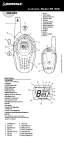

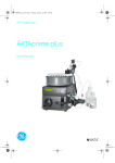


![OverView Control Manager user`s manual - operator [v04]](http://vs1.manualzilla.com/store/data/005659468_1-4c522981c7089838b286d7fbb1120c24-150x150.png)