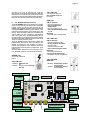
1
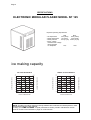
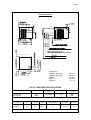
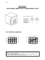
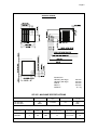
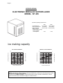
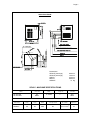
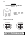
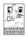
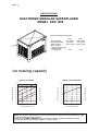
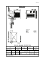
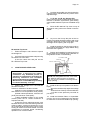
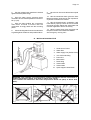
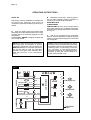
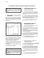
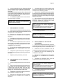
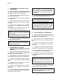
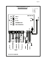
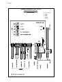
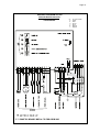
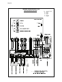
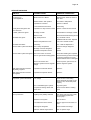
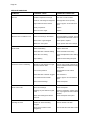
SERVICE MANUAL
SP 125
SP 255
SP 405
SP 605
SPN 1205
R134A - R404A
Electronic modular
flakers and
superflakers
Page 1
TABLE OF
CONTENTS
Table of contents
Specifications SP 125
Specifications SP 255
Specifications SP 405
Specifications SP 605
Specifications SPN 1205
page
1
2
4
6
8
10
GENERAL INFORMATION AND INSTALLATION
Introduction
Unpacking and Inspection - Ice maker
Unpacking and Inspection - Storage bin
Location and levelling
Electrical connections
Water supply and drain connections
Final check list
Installation practice
12
12
12
13
14
14
14
15
OPERATING INSTRUCTIONS
Start up
Operational checks
16
18
PRINCIPLE OF OPERATION (How it works)
Water circuit
Refrigerant circuit
Mechanical system
Operating pressures
Components description
21
22
24
25
26
ADJUSTMENT, REMOVAL AND REPLACEMENT PROCEDURES
Adjustment of the evaporator water level
Replacement of evaporator temperature sensor
Replacement of condenser temperature sensor
Replacement of ice level light control
Replacement of P.C. Board
Replacement of the ice spout
Replacement of the auger, water seal, bearings and coupling
Replacement of the gear motor assy
Replacement of fan motor
Replacement of drier
Replacement of the freezing cylinder
Replacement of air cooled condenser
Replacement of water cooled condenser
Replacement of water regulating valve (water cooled models)
Replacement of compressor
Wiring diagram
Service diagnosis
30
30
30
30
31
31
31
32
32
33
33
33
34
34
34
35
39
MAINTENANCE AND CLEANING INSTRUCTIONS
General
Icemaker
Cleaning instructions of water system
41
41
41
Page 2
SPECIFICATIONS
ELECTRONIC MODULAR FLAKER MODEL SP 125
Important operating requirements:
MIN
• Air temperature
10°C (50°F)
• Water temperature
5°C (40°F)
• Water pressure
1 bar (14 psi)
• Electr. voltage
• variations from voltage
• rating specified
• on nameplate
-10%
MAX
40°C (100°F)
35°C (90°F)
5 bars (70 psi)
+10%
ice making capacity
WATER COOLED MODELS
115
21
115
32
100
38
95
90
85
80
ICE PRODUCED PER 24 HRS.
110
105
o°C
10
110
21
105
32
38
100
95
90
85
80
32
27
21
15
WATER TEMPERATURE
10 o°C
32
27
21
15
10 o°C
WATER TEMPERATURE
NOTE. The daily ice-making capacity is directly related to the condenser air inlet temperature, water
temperature and age of the machine.
To keep your S IMA G FLAKER at peak performance levels, periodic maintenance checks
must be carried out as indicated on page 41 of this manual.
AMBIENT TEMPERATURE
10
Kg.
120
o°C
AMBIENT TEMPERATURE
ICE PRODUCED PER 24 HRS.
AIR COOLED MODELS
Kg.
120
Page 3
SPECIFICATIONS
Dimensions:
HEIGHT (less legs)
HEIGHT (with legs)
WIDTH
DEPTH
WEIGHT
525 mm.
542 mm.
560 mm.
533 mm.
49 Kg.
SP 125 - MACHINE SPECIFICATIONS
Model
Cond. unit
SP 125 AS
SP 125 WS
Basic electr.
230/50/1
Air
Water
Finish
Comp. HP
S. Steel
3/8
Water req.
lt/24 HR
120*
480*
Amps
Start
Amps
Watts
Electric power cons.
Kwh per 24 HR
Nr. of wires
Amps fuse
3.2
17
500
11
3 x 1.5 mm2
10
* A 15°C water temperature
Page 4
SPECIFICATIONS
ELECTRONIC MODULAR FLAKER MODEL SP 255
Important operating requirements:
MIN
• Air temperature
10°C (50°F)
• Water temperature
5°C (40°F)
• Water pressure
1 bar (14 psi)
• Electr. voltage
• variations from voltage
• rating specified
• on nameplate
-10%
MAX
40°C (100°F)
35°C (90°F)
5 bars (70 psi)
+10%
ice making capacity
32
38
160
140
120
32
27
21
15
WATER TEMPERATURE
10 o°C
180
170
160
150
32
27
21
15
10 o°C
WATER TEMPERATURE
NOTE. The daily ice-making capacity is directly related to the condenser air inlet temperature, water
temperature and age of the machine.
To keep your S IMA G FLAKER at peak performance levels, periodic maintenance checks
must be carried out as indicated on page 41 of this manual.
AMBIENT TEMPERATURE
180
Kg.
190
DE 10 A 38°C
10
21
ICE PRODUCED PER 24 HRS.
WATER COOLED MODELS
o°C
AMBIENT TEMPERATURE
ICE PRODUCED PER 24 HRS.
AIR COOLED MODELS
Kg.
200
Page 5
SPECIFICATIONS
Dimensions:
HEIGHT (less legs)
HEIGHT (with legs)
WIDTH
DEPTH
WEIGHT
525 mm.
542 mm.
533 mm.
533 mm.
49 Kg.
SP 255 - MACHINE SPECIFICATIONS
Model
SP 255 AS
SP 255 WS
Basic electr.
230/50/1
Cond. unit
Finish
Comp. HP
Water req.
lt/24 HR
Air
Water
S. Steel
3/4
200*
850*
Amps
Start
Amps
Watts
Electric power cons.
Kwh per 24 HR
Nr. of wires
Amps fuse
4
20
760
17
3 x 1.5 mm2
10
* A 15°C water temperature
Page 6
SPECIFICATIONS
ELECTRONIC MODULAR SUPERFLAKER
MODEL SP 405
Important operating requirements:
MIN
10°C (50°F)
5°C (40°F)
1 bar (14 psi)
MAX
40°C (100°F)
35°C (90°F)
5 bars (70 psi)
-10%
+10%
• Air temperature
• Water temperature
• Water pressure
• Electr. voltage
• variations from voltage
• rating specified
• on nameplate
ice making capacity
10
21
310
290
270
32
250
38
230
210
27
21
15
WATER TEMPERATURE
10 o°C
ICE PRODUCED PER 24 HRS.
330
190
32
Kg.
360
o°C
AMBIENT TEMPERATURE
ICE PRODUCED PER 24 HRS.
Kg.
310
WATER COOLED MODELS
o°C
340
10
21
32
38
320
300
280
260
240
220
200
32
27
21
15
10 o°C
WATER TEMPERATURE
NOTE. The daily ice-making capacity is directly related to the condenser air inlet temperature, water
temperature and age of the machine.
To keep your S IMA G FLAKER at peak performance levels, periodic maintenance checks
must be carried out as indicated on page 41 of this manual.
AMBIENT TEMPERATURE
AIR COOLED MODELS
Page 7
SPECIFICATIONS
Dimensions:
HEIGHT (less legs)
HEIGHT (with legs)
WIDTH
DEPTH
WEIGHT
690 mm.
705 mm.
535 mm.
660 mm.
77 Kg.
SP 405 - MACHINE SPECIFICATIONS
Model
SP 405 AS
SP 405 WS
Basic electr.
230/50/1
Cond. unit
Finish
Air
Water
S. Steel
Comp. HP
Water req.
lt/24 HR
320*
1800*
1
Amps
Start
Amps
Watts
Electric power cons.
Kwh per 24 HR
Nr. of wires
Amps fuse
5.2
29
1200
26
3 x 1.5 mm 2
16
* A 15°C water temperature
Page 8
SPECIFICATIONS
ELECTRONIC MODULAR SUPERFLAKER
MODEL SP 605
Important operating requirements:
MIN
• Air temperature
10°C (50°F)
• Water temperature
5°C (40°F)
• Water pressure
1 bar (14 psi)
• Electr. voltage
• variations from voltage
• rating specified
• on nameplate
-10%
MAX
40°C (100°F)
35°C (90°F)
5 bars (70 psi)
+10%
ice making capacity
10
21
600
550
32
500
38
450
400
350
27
21
15
WATER TEMPERATURE
10 o°C
ICE PRODUCED PER 24 HRS.
650
300
32
Kg.
600
o°C
AMBIENT TEMPERATURE
ICE PRODUCED PER 24 HRS.
Kg.
700
WATER COOLED MODELS
o°C
10
21
32
38
575
550
525
500
475
450
425
400
32
27
21
15
10 o°C
WATER TEMPERATURE
NOTE. The daily ice-making capacity is directly related to the condenser air inlet temperature, water
temperature and age of the machine.
To keep your S IMA G FLAKERat peak performance levels, periodic maintenance checks
must be carried out as indicated on page 41 of this manual.
AMBIENT TEMPERATURE
AIR COOLED MODELS
Page 9
SPECIFICATIONS
Dimensions:
HEIGHT (less legs)
HEIGHT (with legs)
WIDTH
DEPTH
WEIGHT
830 mm.
845 mm.
535 mm.
660 mm.
93 Kg.
SP 605 - MACHINE SPECIFICATIONS
Model
SP 605 AS
SP 605 WS
Basic electr.
230/50/1
400/50/3+N
Cond. unit
Finish
Comp. HP
Water req.
lt/24 HR
Air
Water
S. Steel
1.5
600*
3000*
Amps
Start
Amps
10
4
34
22
* A 15°C water temperature
Watts
2000
Electric power cons.
Kwh per 24 HR
45
40
Nr. of wires
Amps fuse
3 x 1.5 mm2
5 x 1.5 mm2
16
16
Page 10
SPECIFICATIONS
ELECTRONIC MODULAR SUPERFLAKER
MODEL SPN 1205
Important operating requirements:
MIN
• Air temperature
10°C (50°F)
• Water temperature
5°C (40°F)
• Water pressure
1 bar (14 psi)
• Electr. voltage
• variations from voltage
• rating specified
• on nameplate
-10%
MAX
40°C (100°F)
35°C (90°F)
5 bars (70 psi)
+10%
ice making capacity
WATER COOLED MODELS
Kg.
1400
1050
1000
32
950
38
900
850
800
750
700
ICE PRODUCED PER 24 HRS.
1300
21
AMBIENT TEMPERATURE
ICE PRODUCED PER 24 HRS.
1100
°C
DE 10 A 38°C
°C
10
1200
1100
32
1000
38
900
800
700
600
500
32
27
21
15
WATER TEMPERATURE
10 o°C
32
27
21
15
10 o°C
WATER TEMPERATURE
NOTE. The daily ice-making capacity is directly related to the condenser air inlet temperature, water
temperature and age of the machine.
To keep your S IMA G FLAKERat peak performance levels, periodic maintenance checks
must be carried out as indicated on page 41 of this manual.
AMBIENT TEMPERATURE
AIR COOLED MODEL
Kg.
1150
Page 11
SPECIFICATIONS
Dimensions:
HEIGHT
WIDTH
DEPTH
WEIGHT
850 mm.
1065 mm.
698 mm.
179 Kg.
SPN 1205 - MACHINE SPECIFICATIONS
Model
SPN 1205 AS
SPN 1205 WS
Basic electr.
230/50/3
400/50/3 + N
Cond. unit
Finish
Comp. HP
Water req.
lt/24 HR
Air
Water
S. Steel
2.5
1150*
8000*
Amps
Start
Amps
7,1
3,4
56
28
* A 15°C water temperature
Watts
Electric power cons.
Kwh per 24 HR
3600
80
Nr. of wires
4 x 2.5 mm 2
5 x 2.5 mm 2
Amps fuse
25
16
Page 12
GENERAL INFORMATION AND INSTALLATION
A.
INTRODUCTION
This manual provides the specifications and the
step-by-step procedures for the installation, startup and operation, maintenance and cleaning for
the SIMAG SP 125, SP 255, SP 405,
SP 605 and SPN 1205 Modular Icemakers.
The Electronic Flakers and Superflakers are
quality designed, engineered and manufactured.
Their ice making systems are thoroughly tested
providing the utmost in flexibility to fit the needs
of a particular user.
NOTE. To retain the safety and performance
built into this icemaker, it is important that
installation and maintenance be conducted
in the manner outlined in this manual.
4. On models SP 125, SP 255, SP 405 and SP 605
remove the front/top panel while on model
SPN 1205 remove top and sides panels of the unit
and inspect for any concealed damage. Notify
carrier of your claim for the concealed damage
as stated in step 2 above.
5. Remove all internal support packing and
masking tape.
6. Check that refrigerant lines do not rub
against or touch other lines or surfaces, and that
the fan blades move freely.
7. Check that the compressor fits snugly onto
all its mounting pads.
8. See data plate on the rear side of the unit
and check that local main voltage corresponds
with the voltage specified on it.
Storage Bin
Since the SP series Modular Flakers do not have
their own attached ice storage bins, it is necessary
to use an auxiliary bin as detailed herebelow:
R 85 in combination with SP 125 and
SP 255
R 155 with its companion RP 155 Top
Cover in combination with SP 125, SP 255,
SP 405 and SP 605
R 250 with its companion RP 250 Top
Cover in combination with SP 405 and SP 605
CAUTION. Incorrect voltage supplied to
the icemaker will void your parts
replacement program.
9. Remove the manufacturer’s registration
card from the inside of the User Manual and fillin all parts including: Model and Serial Number
taken from the data plate.
Forward the completed self-addressed registration card to SIMAG.
Storage bin (R 85 - R 155 - R 250)
B.
UNPACKING AND INSPECTION
Icemaker
1. Call your authorized SIMAG Distributor
or Dealer for proper installation.
2. Visually inspect the exterior of the packing
and skid. Any severe damage noted should be
reported to the delivering carrier and a concealed
damage claim form filled in subjet to inspection of
the contents with the carrier’s representative
present.
3. a) Cut and remove the plastic strip securing
the carton box to the skid.
b) Cut open the top of the carton and remove the
polystyre protection sheet.
c) Pull out the polystyre posts from the corners
and then remove the carton.
1. Follow the steps 1, 2 and
unpack the storage bin.
3 above to
2. Unloose the two bolts and remove the protection plate from the drain fitting on model R 250.
3. Carefully lay it down on its rear side and fit
the four legs into their sockets.
4. Remove all internal support packing and
masking tape as well as the plastic ice cube
deflector which is not used with the SIMAG
Modular Flakers.
5. Remove the manufacturer’s registration
card from the inside of the User Manual and fillin all parts including: Model and Serial Number
taken from the data plate.
Forward the completed self-addressed registration card to SIMAG.
Storage bin (B 1025 S - B 1350 S)
1. Follow the steps 1, 2 and
unpack the storage bin.
3 above to
Page 13
2. Level the Storage Bin Assy in both the left to
right and front to rear directions by means of the
adjustable legs.
3. On R 155 and R 250 Storage Bin
inspect its top mounting gasket which should be
flat with no wrinkles, to provide a good sealing
when the RP 155/250 Top Cover is installed on top
of it.
4. Place the RP 250/155 Top Cover on top of
Storage bin using care not to wrinkle or tear the
gasket.
5. On the B 1025 S and B 1350 S Storage
Bin unloose the screws securing the S.S. Top
Cover to the storage bin and remove it.
6. Lay out on the bin top the plan of the ice
machine as it will be located on the bin and cut an
opening in the bin top for the ice drop area; cover
the edges of the opening with vinyl tape.
RP 250/155 Top Cover
1. Follow the steps 1 and 2 above to unpack
the storage bin.
2. a) Cut and remove the plastic strip securing
the carton box to the skid.
b) Cut the carton box and pull out the
RP 250/155 Top Cover.
C.
7. Install the gasket-on the bin top-around ice
drop opening of the bin top; apply sealant along
the inside of the gasket.
8. Position and install the four aluminium front
to rear stiffeners (U shaped) paying attention to
the guideline shown on the drawing.
CUT GASKET HERE
STIFFENER
BIN WALL GAKET
LOCATION AND LEVELLING
WARNING. This Modular Flaker and
Superflaker is designed for indoor
installation only. Extended periods of
operation at temperature exceeding the
following limitations will constitute
misuse under the terms of the SIMAG
Manufacturer’s Limited Warranty resulting
in LOSS of warranty coverage.
1. Position the storage bin in the selected
permanent location.
Criteria for selection of location include:
a) Minimum room temperature 10°C (50°F)
and maximum room temperature 40°C (100°F).
b) Water inlet temperatures: minimum 5°C
(40°F) and maximum 35°C (90°F).
c) Well ventilated location for air cooled
models (clean the air cooled condenser at
frequent intervals).
d) Service access: adequate space must
be left for all service connections through the rear
of the ice maker. A minimum clearance of 15 cm
(6") must be left at the sides of the unit for routing
cooling air drawn into and exhausted out of the
compartment to maintain proper condensing
operation of air cooled models.
TOP SHELL
NOTE. Bin wall gasket must be cut to clear
the stiffener ends as shown on drawing.
Do not put any stiffeners crossing the ice
drop opening.
9. Install the bin top in its position onto the bin
top by:
- place the rear side of top against rear edge
of the bin
- lower the front of the top onto the stiffeners
- re-fit the screws previously removed as
per step 5
10. Install the Modular Flaker or Superflaker
onto the Top Cover of storage bin pay attention
to match the ice chute with the Bin Top opening.
Installation of lift door catch (B 1025 S)
On the Storage Bin B 1025 S when the ice maker
is installed flush with the bin front it is required to
mount the lift door catch as detailed herebelow.
Page 14
1. Open all the way the lift door in the upright
position then place the door catch on the front
face of the ice maker and tape it in place.
2. Drill two 3 mm holes in correspondance of
the catch mounting holes.
3. Remove the tape and fasten the catch
using the two self-tapping screws supplied.
D.
ELECTRICAL CONNECTIONS
See data plate for current requirements to
determine wire size to be used for electrical
connections. All SIMAG icemakers require
a solid earth wire.
All SIMAG ice machines are supplied from
the factory completely pre-wired and require only
electrical power connections to the wire cord
provided at the rear of the unit.
Make sure that the ice machine is connected to
its own circuit and individually fused (see data
plate for fuse size).
The maximum allowable voltage variation should
not exceed -10% and +10% of the data plate
rating. Low voltage can cause faulty functioning
and may be responsible for serious damage to
the overload switch and motor windings.
NOTE. All external wiring should conform to
national, state and local standards and
regulations.
Check voltage on the line and the ice maker’s
data plate before connecting the unit.
E.
WATER SUPPLY AND DRAIN
CONNECTIONS
fitting and a shut-off valve installed in an accessible
position between the water supply line and the
unit.
If water contains a high level of impurities, it is
advisable to consider the installation of an
appropriate water filter or conditioner.
WATER SUPPLY - WATER COOLED MODELS
The water cooled versions of SIMAG Ice
Makers require two separate inlet water supplies,
one for the water making the flaker ice and the
other for the water cooled condenser.
Connect the 3/4" GAS male fitting of the water
inlet, using the flexible hose supplied to the cold
water supply line with regular plumbing fitting and
a shut-off valve installed in an accessible position
between the water supply line and the unit.
WATER DRAIN
The recommended drain tube is a plastic or
flexible hose with 18 mm (3/4") I.D. which runs to
an open trapped and vented drain. When the
drain is a long run, allow 3 cm pitch per meter
(1/4" pitch per foot).
Install a vertical open vent on drain line high point
at the unit drain connection to ensure good
draining.
The ideal drain receptacle is a trapped and vented
floor drain.
WATER DRAIN - WATER COOLED MODELS
Connect the 3/4" GAS male fitting of the condenser
water drain, utilizing a second flexible hose to the
open trapped and vented drain.
This additional drain line must not interconnect to
any other of the units drains.
GENERAL
When choosing the water supply for the ice flaker
consideration should be given to:
a) Length of run
b) Water clarity and purity
c) Adequate water supply pressure
Since water is the most important single ingredient
in producting ice you cannot emphasize too
much the three items listed above.
Low water pressure, below 1 bar may cause
malfunction of the ice maker unit.
Water containing excessive minerals will tend to
produce scale build-up on the interior parts of the
water system while too soft water (with too lo
contents of mineral salts), will produce a very
hard flaker ice.
NOTE. The water supply and the water drain
must be installed to conform with the local
code. In some case a licensed plumber and/
or a plumbing permit is required.
F.
FINAL CHECK LIST
1. Is the unit in a room where ambient
temperatures are within a minimum of 10°C (50°F)
even in winter months?
2. Is there at least a 15 cm (6") clearance
around the unit for proper air circulation?
WATER SUPPLY
3.
Is the unit level? (IMPORTANT)
Connect the 3/4" GAS male of the water inlet
fitting, using the food grade flexible hose supplied
to the cold water supply line with regular plumbing
4. Have all the electrical and plumbing
connections been made, and is the water supply
shut-off valve open?
Page 15
5. Has the voltage been tested and checked
against the data plate rating?
9. Have the bin liner and cabinet been wiped
clean?
6. Has the water supply pressure been
checked to ensure a water pressure of at least 1
bar (14 psi).
10. Has the owner/user been given the User
Manual and been instructed on the importance
of periodic maintenance checks?
7. Have the bolts holding the compressor
down been checked to ensure that the
compressor is snugly fitted onto the mounting
pads?
8. Check all refrigerant lines and conduit lines
to guard against vibrations and possible failure.
11. Has the Manufacturer’s registration card
been filled in properly? Check for correct model
and serial number against the serial plate and
mail the registration card to the factory.
12. Has the owner been given the name and
the phone number of the authorized SIMAG
Service Agency serving him?
G. INSTALLATION PRACTICE
1.
2.
3.
4.
5.
6.
7.
8.
9.
10.
Hand shut-off valve
Water filter
Water supply line (flexible hose)
3/4" GAS male fitting
Power line
Main switch
Drain fitting
Vented drain
Vented drain
Open trapped vented drain
WARNING. This icemaker is not designed for outdoor installation and will not function in
ambient temperatures below 10°C (50°F) or above 40°C (100°F).
This icemaker will malfunction with water temperatures below 5°C (40°F) or above 35°C
(90°F).
Page 16
OPERATING INSTRUCTIONS
B. Elapsed the 3 minutes - stand by period the unit starts operating with the activation in
sequence of the following assemblies:
GEAR MOTOR/S
COMPRESSOR
FAN MOTOR/S (if unit is an air cooled version)
kept under control by the condenser temperature sensor which has its probe within the condenser
fins (Fig.2).
START UP
After having correctly installed the ice maker and
completed the plumbing and electrical
connections, perform the following “Start-up” procedure.
A. Open the water supply line shutoff valve
and put the unit under electrical power by moving
the main switch, on the power supply line, to the
ON position.
The first LED - GREEN - will glow to signal that
unit is under power.
C. After 2 or 3 minutes from the compressor
start up, observe that flaker ice begins dropping
off the ice spout to fall through the ice chute into
the storage bin.
NOTE. Every time the unit is put under power,
after being kept for sometime in shut-off
conditions (electrically disconnected) the
RED LED will blink for 3 minutes after which
the unit will start up with the immediate
operation of the gear motor assembly and,
after few seconds, of the compressor
(Fig.1).
NOTE. The first ice bits that drop into the ice
storage bin are not so hard as the evaporating
temperature has not yet reached the correct
operating value. It is necessary to allow the
ice - just made - to cure itself and wait for
about ten minutes for the evaporating temperature to reach the correct value so to
make more hard bits of ice.
FIG. 1
WATER
LEVEL
RESET
88
GEAR MOTOR
ROTATION
12
CONDENSER TEMP.
T>1°C
11
EVAPORATOR TEMP.
10
77
DATA PROCESSOR
SENSORS
13
RELAYS
55
GEAR MOTOR
44
ICE LEVEL CONTROL
9
COMPRESSOR
CONTACTOR COIL
66
L
1
N
2
33
TRIAC
FAN MOTOR
TRANSF.
ELECTRONIC
CARD
Page 17
FIG. 2
WATER
LEVEL
RESET
88
ROTATION
12
12
CONDENSER TEMP. T 40÷50°C
11
EVAPORATOR TEMP.
10
77
DATA PROCESSOR
SENSORS
13
GEAR MOTOR
RELAYS
55
GEAR MOTOR
44
ICE LEVEL CONTROL
9
COMPRESSOR
CONTACTOR COIL
66
L
1
N
2
33
TRIAC
FAN MOTOR
TRANSF.
ELECTRONIC
CARD
FIG. 3
WATER
LEVEL
RESET
88
GEAR MOTOR
ROTATION
12
12
CONDENSER TEMP.
T>75°C
11
EVAPORATOR TEMP.
10
77
DATA PROCESSOR
SENSORS
13
RELAYS
55
44
ICE LEVEL CONTROL
9
COMPRESSOR
CONTACTOR COIL
66
L
1
N
2
2
GEAR MOTOR
33
TRIAC
FAN MOTOR
TRANSF.
ELECTRONIC
CARD
Page 18
NOTE. On air cooled models, the condenser
temperature sensor, which is located within
the condenser fins, keeps the head
(condensing) pressure between preset
values.
In the event of condenser clogged - such to
prevent the proper flow of the cooling air - or,
in case the fan motor is out of operation, the
condenser temperature rises and when it
reaches 70° C (160°F) for air cooled version and 60° C (140°F) - for water cooled version the condenser temperature sensor shuts-off
the ice maker with the consequent light-up of
the RED WARNING LIGHT (Fig.3).
NOTE. If, after ten minutes from the
compressor start-up, the evaporating temperature has not dropped down to a value
lower than -1°C (30°F) the evaporating temperature sensor detects such an abnormal
situation and stops consequently the unit
operation.
In this circustance, the 5th warning YELLOW
LED will blink.
The machine will remain in OFF mode for
one hour then it will restart automatically.
In case the unit trips OFF again in alarm for
3 times in 3 hours, the machine SHUTS OFF
DEFINITIVELY.
After having diagnosed and eliminated the
cause of the too hi evaporating temperature
(insufficient refrigerant in the system or
compressor not running) it is necessary to
unplug and plug in again to restart the
machine. The unit, before resuming the
normal operation, will go through the usual
3 minutes STAND-BY period.
The machine will remain in OFF mode for
one hour then it will restart automatically.
In case the unit trips OFF again in alarm for
3 times in 3 hours, the machine SHUTS OFF
DEFINITIVELY.
After having diagnosed the reason of the
temperature rise and removed its cause, it is
necessary to proceed as per the previous
“NOTE” to start up again the operation of the
ice maker.
OPERATION CHECKS UPON THE UNIT
START UP
E. Check for the correct CUT-OUT and
CUT-IN of the water level sensor by first shutting
closed the water shutoff valve on the water
supply line.
D. Remove front service panel and, if
necessary, install the refrigerant service gauges
on the corresponding service valves to check
both the HI and LO refrigerant pressures.
FIG. 4
WATER
LEVEL
RESET
88
GEAR MOTOR
ROTATION
12
12
CONDENSER TEMP.
11
EVAPORATOR TEMP.
10
77
DATA PROCESSOR
SENSORS
13
RELAYS
55
44
ICE LEVEL CONTROL
9
COMPRESSOR
CONTACTOR COIL
66
L
L
1
N
2
2
GEAR MOTOR
33
TRIAC
FAN MOTOR
TRANSF.
ELECTRONIC
CARD
Page 19
Opening the water supply line shutoff valve to fill
up again the float reservoir, the YELLOW LED
goes off while the RED LED starts blinking.
After 3 minutes the unit resumes its total operation
with the immediate start-up of the gear motor
and, few seconds later, of the compressor.
This will cause a gradual decrease of the water
level in the float reservoir and as soon as the
level gets below the two vertical metal pins, the
flaker stops to operate and the YELLOW warning
LED will glow to signal the shortage of water
(Fig. 4)
F. Check for the correct operation of the
electronic eye (one per each ice chute on model
SP1205) of the optical ice level control, by closing
the bottom opening of the vertical ice chute.
Wait the built up of the ice into the ice chute till it
cuts the light beam of the sensing "eyes".
This interruption will cause an immediate blinking
of the Bin Full YELLOW LED located on the front
of the P.C. Board and after about 6 seconds
causes the shutoff of the unit with the
simultaneous lighting (steady) of the Same LED
signalling the full bin situation (Fig.5).
NOTE. The water level sensor detects the
presence of water in the float reservoir and
confirms it to the micro processor by
maintaining a low voltage current flow
between the two metal pins using the water
as conductor.
WARNING. The use of de-mineralized
water (water with no salt content) having
an electrical conductivity lower than 30
µS, will cause break with the consequent
CUT-OUT of the flaker and the glowing of
the YELLOW LED of water shortage, even
with water in the reservoir.
Discharge the ice from the ice chute so to resume
the light beam previously interrupted and after
about 6 seconds the flaker will re-start - through
the 3 minutes STAND-BY period - with the
extinguishing of the YELLOW LED.
FIG. 5
WATER
LEVEL
RESET
88
ROTATION
12
12
CONDENSER TEMP.
11
11
EVAPORATOR TEMP.
10
10
77
DATA PROCESSOR
SENSORS
13
GEAR MOTOR
RELAYS
55
GEAR MOTOR
44
ICE LEVEL CONTROL
9
COMPRESSOR
CONTACTOR COIL
66
L
1
N
2
33
TRIAC
FAN MOTOR
TRANSF.
ELECTRONIC
CARD
Page 20
NOTE. The ICE LEVEL CONTROL
(INFRARED SYSTEM) is independent of the
temperature however, the reliability of its
detection can be affected by external light
radiations or by any sort of dirt and scale
sediment which may deposit directly on the
light source and on the receiver.
To prevent any possible ice maker
malfunction, it is advisable to locate the unit
where it can't be reached by any direct light
beam or light radiation and to follow the
instructions for the periodical cleaning of the
light sensor elements as detailed in the
MAINTENANCE AND CLEANING PROCEDURES.
NOTE. In the front of the PC Board is located
a small I/R Trimmer directly connected with
the optical Ice level control. By means of its
screw it is possible to modify the signal
received from the Ice Level control so to
overcame some problem caused by dirt and/
or low power supply.
When adjusted it is very important to check
for its correct operation using ice (NOT
HAND) to break the Infrared Beam. In case
the machine doesn't stop it means that the
new setting is too much powerfull and need to
be reduced always by means of the I/R Trimmer.
M. If previously installed, remove the refrigerant
service gauges and re-fit the unit service panels
previously removed.
N. Instruct the owner/user on the general
operation of the ice machine and about the
cleaning and care it requires.
Page 21
PRINCIPLE OF OPERATION
WATER CIRCUIT
SP 125-255
ICE SPOUT
The water enter in the machine through the
water inlet fitting which incorporates a strainer located at the rear side of the cabinet - then it
goes to the water reservoir flowing through a
float valve.
The float reservoir is positioned at the side of the
freezing at such an height to be able to maintain
a constant water level. The water flows from the
reservoir into the bottom inlet of the freezer to
sorround the stainless steel auger which is
vertically fitted in the center of the freezer.
In the freezer the incoming water gets chilled into
soft (slush) ice which is moved upward by the
rotating action of the auger. The auger rotates
counter-clockwise within the freezer powered by
a direct drive gear motor and carries the ice
upward along the refrigerated freezer inner walls
and by doing so the ice gets progressively thicker
and harder.
The ice, being costantly lifted up, meet the teeth
of the ice breaker which is fitted on the top end of
the auger, where it gets compacted, cracked and
forced to change from vertical into horizontal
motion to be discharged out, through the ice
spout and chute, into the storage bin.
FLOAT VALVE
WATER INLET LINE
FREEZER
FREEZER WATER
FEED LINE
SP 405-605
ICE SPOUT
FLOAT TANK
FLOAT VALVE
FREEZER
WATER INLET LINE
NOTE. The presence of the water in the float
reservoir is detected by a system of two
sensors which operates in conjunction with
the P.C. Board. The two sensors use the
water as a conductor to maintain a low
voltage current flow between them. In case
the water used is very soft (de-mineralized)
or the float reservoir gets empty the current
flow between the sensors become so weak
or is no longer maintained that, as
consequence, the P.C. Board shutoff the
flaker operation with the simultaneous
glowing of the YELLOW LED signalling
“Shortage of water”.
FLOAT TANK
FREEZER
WATER
FEED LINE
SPN 1205
FLOAT TANK
FLOAT VALVE
ICE SPOUT
WATER INLET LINE
FREEZER
FREEZER
WATER
FEED LINE
Page 22
As some ice gets scooped out from the storage
bin, the light beam between the two sensors
resumes and six seconds later the ice machine
restarts the ice making process - going always
through the 3' stand by - and the YELLOW LED
goes off.
REFRIGERANT CIRCUIT
MSPN 1205
The hot gas refrigerant discharged out
from the compressor reaches the
condenser where, being cooled down,
condenses into liquid.
Flowing into the liquid line it passes
through the drier filter, then it goes all
SUCTION LINE
the way through the capillary tube where
it looses some of its pressure so that its
pressure and temperature are lowered.
Next, the refrigerant enters into the
ACCUMULATOR
evaporator coil wrapped around the
freezer inner tube.
The water being constantly fed at the
interior of the freezer inner tube, exchange heat with the refrigerant circulating
into the evaporator coil, this cause the
refrigerant to boil-off and evaporate,
thereby it changes from liquid into vapor.
The vapor refrigerant then passes
through the suction accumulator and
through the suction line where the
refrigerant exchanges heat with the one
flowing into the capillary tube (warmer)
before being sucked into the compressor
to be recirculated.
The refrigerant head pressure is kept
COMPRESSOR
between two pre-set values (8÷9 bar 110÷125 psig on SP 125 and 17÷18
bar - 240÷250 psig on SP 2555, SP405,
SP 650 and SPN 1205) by the condenser
temperature sensor which has its probe
located within the condenser fins - in air
cooled versions.
SP 125-255-405-605
EVAPORATOR
ACCUMULATOR
CAPILLARY TUBE
CONDENSER
NOTE. The interruption of the light beam
between the two light sensors is immediately
signalled by the blinking of the BIN FULL
YELLOW LED located on the front of the
P.C. Board.
After about 6" of steady interruption of the
light beam the unit stops and the “Full Bin”
YELLOW LED glows steady.
The six seconds of delay prevent the unit
from stopping for any undue reason like the
momentarily interruption of the light beam
caused by the flakes that slides along the ice
spout before dropping into the bin.
This condenser temperature sensor, when senses
a rising of the condenser temperature beyond
the pre-fixed limit, changes its electrical resistance
and send a low voltage power flow to the MICROPROCESSOR of the P.C. Board which energizes,
through a TRIAC, the Fan Motor in ON-OFF mode.
On the water cooled versions, the refrigerant
head pressure is kept at the constant value of
8.5 bar (120 psig) on SP 125 and of 17 bar
(240 psig) on SP255, SP405, SP605 and SPN 1205
by the metered amount of water passing through
the condenser which is regulated by the action of
the Water Regulating Valve that has its capillary
SUCTION LINE
By running the ice maker, i.e. by putting the unit
under power, starts the automatic and continuous
icemaking process which would not stop until the
ice storage bin gets filled-up to the level of the
control “eyes” located on the ice chute. As the ice
level raises to interrupt the light beam running
between the two infrared leds (one or both on
model SPN1205), the unit stops after six seconds,
with the simulteneous glowing of the YELLOW
LED signalling the “Full Bin” situation.
DISCHARGE LINE
COMPRESSOR
FAN MOTOR
EVAPORATOR
CAPILLARY TUBE
DISCHARGE LINE
CONDENSER
DRIED
FAN MOTOR
Page 23
tube connected to the liquid refrigerant line. As
pressure increases, the water regulating valve
opens to increase the flow of cooling water to the
condenser.
The RED LED starts blinking and three
minutes later the flaker unit resume its normal
operating mode. The condenser temperature sensor has a further safety function which
consist in preventing the unit from operating
in Lo-ambient conditions i.e. when the
condenser temperature - equivalent to the
ambient temperature - is lower then 1°C
34°F (Fig.6).
As soon as the ambient temperature rises up
to 5 °C the P.C. Board restarts automatically
the machine on the three minutes starting
time.
NOTE. In case the condenser temperature
probe senses that the condenser temperature has rised to 70°C on air cooled version
- or 60° C on water cooled version - for one of
the following abnormal reasons:
CLOGGED CONDENSER (Air cooled
version)
INSUFFICIENT FLOW OF COOLING
WATER (Water cooled version)
FAN MOTOR OUT OF OPERATION (Air
cooled version)
AMBIENT TEMPERATURE HIGHER THEN
43°C (110°F)
it causes the total and immediate SHUT-OFF
of the machine in order to prevent the unit
from operating in abnormal and dangerous
conditions.
When the ice maker stops on account of this
protective device, there is a simultaneous
glowing of the RED LED, warning the user of
the Hi Temperature situation.
The machine will remain in OFF mode for
one hour then it will restart automatically.
In case the unit trips OFF again in alarm for
3 times in 3 hours, the machine SHUTS OFF
DEFINITIVELY.
After having eliminated the source of the
excessive condenser temperature, to restart
the ice machine it is necessary to unplug and
plug in again.
The refrigerant suction or Lo-pressure sets - in
normal ambient conditions - on the value of
0.5 bar (7 psig) on SP125 and of 2.4÷2.6 bar
(34÷36 psig) on SP255, SP405, SP605 and
SPN 1205 after few minutes from the unit start-up.
This value can vary of 0.1 or 0.2 bar (1.5÷3 psig)
in relation to the water temperture varia-tions
influencing the freezer cylinder.
NOTE. If, after ten minutes from the unit start
up, no ice is made and the evaporating
temperature detected by the evaporator
sensor results to be higher than -1°C (30°F)
the ice maker stops and the 5th WARNING
YELLOW LED blinks.
The machine will remain in OFF mode for
one hour then it will restart automatically.
In case the unit trips OFF again in alarm for
3 times in 3 hours, the machine SHUTS OFF
DEFINITIVELY.
FIG. 6
WATER
LEVEL
RESET
88
ROTATION
12
12
CONDENSER TEMP.
T<1°C
11
11
EVAPORATOR TEMP.
10
10
77
DATA PROCESSOR
SENSORS
13
GEAR MOTOR
RELAYS
55
GEAR MOTOR
44
ICE LEVEL CONTROL
9
COMPRESSOR
CONTACTOR COIL
66
L
L
1
N
N
2
33
TRIAC
FAN MOTOR
TRANSF.
ELECTRONIC
CARD
Page 24
MECHANICAL SYSTEM
RE-SET push button or switch OFF and ON
the power line main disconnnect switch
(Fig. 7).
The mechanical system of the SIMAG Flaker
machines consists basically of a gear motor
assembly (two on model SPN1205) which drives,
through a ratched coupling, a worn shaft or auger
placed on its vertical axis within the freezing
cylinder (two on model SP 1205).
The gear motor is made of a single phase electric
motor with a permanent capacitor. This motor is
directly fitted in the gear case through which it
drives - in counter clockwise rotation at a speed
of 9.5 r.p.m. - the freezer auger being linked to it
by the ratched coupling.
The machine will remain in OFF mode for
one hour then it will restart automatically.
In case the unit trips OFF again in alarm for
3 times in 3 hours, the machine SHUTS OFF
DEFINITIVELY.
The RED LED will start blinking and after 3
minutes the ice maker will resume its total
operations by running first the gear motor
and then the compressor.
NOTE. In the event the gear motor (one of
the two on SPN1205 ) will tend to rotate in the
wrong direction (counterclockwise) or not
rotating at all or rotating at lower speed the
unit will stop immediately with the glowing
of the WARNING YELLOW LED on account
of the intervention of the Electromagnetic
Safety Device - based on Hall Effect principle.
After having diagnosed and eliminated the
source of the gear motor wrong rotation, to
restart the unit it is necessary to press the
Too low ambient and water temperature (well
below the limitations of respectively 10°C and
5°C - 50°F and 40°F) or frequent interruptions of
the water supply to the freezing cylinder (clogging
of the water hose connecting the float reservoir to
the water inlet at the bottom of the freezer) may
cause the ice to get too hard and compact loosing
fluidity and thereby seizing the auger.
This situation will put under excessive strain
and load the entire drive system and freezer
bearings.
FIG. 7
WATER
LEVEL
RESET
88
ROTATION
12
12
CONDENSER TEMP.
11
EVAPORATOR TEMP.
10
77
DATA PROCESSOR
SENSORS
13
GEAR MOTOR
RELAYS
55
GEAR MOTOR
44
ICE LEVEL CONTROL
9
COMPRESSOR
CONTACTOR COIL
66
L
1
N
2
33
TRIAC
FAN MOTOR
TRANSF.
ELECTRONIC
CARD
Page 25
REFRIGERANT METERING DEVICE:
REFRIGERANT CHARGE (R 404 A)
capillary tube
SP 255
SP 405
SP 605
SPN 1205
REFRIGERANT CHARGE (R 134 A)
Air cooled
SP 125
440 gr
Water cooled
400 gr
Air cooled
660 gr
750 gr
880 gr
2400 gr
Water cooled
520 gr
600 gr
820 gr
1200 gr
NOTE. Before charging the refrigerant system
always check the type of refrigerant and quantity
as specified on the individual ice machine
dataplate. The refrigerant charges indicated
are relatives to averages operating conditions.
OPERATING PRESSURES (With 21°C ambient temperature)
Discharge pressure:
SP 125
SP 255 - 405 - 605
SPN 1205
Air cooled version
8 ÷ 9 bar
17 ÷ 18 bar
17 ÷ 18 bar
Water cooled version
8,5 bar
17 bar
17 bar
Suction pressure:
0,5 bar
2.5 bar
2.4 bar
Page 26
COMPONENTS DESCRIPTION
A.
EVAPORATOR TEMPERATURE
SENSOR
The evaporator sensor probe is inserted into its
tube well, which is welded on the evaporator
outlet line, it detects the temperature of the
refrigerant on the way out from the evaporator
and signals it by suppling a low voltage current
flow to the P.C. Board.
According to the current received, the microprocessor let the ice maker to continue its
operations or not. In case the evaporating temperature, after 10 minutes from the unit start-up,
does not go below -1°C (30°F) the evaporator
sensor signals to stop immediately the unit
operation, with the blinking of the 5th Warning
YELLOW LED.
NOTE. The machine will remain in OFF mode
for one hour then it will restart automatically.
In case the unit trips OFF again in alarm for
3 times in 3 hours, the machine SHUTS OFF
DEFINITIVELY.
To restart the unit after the shutoff caused by
the hi evaporating temperature, it is necessary to switch OFF and ON the power line
main disconnect Switch.
B. WATER LEVEL SENSOR
This sensor consists of two small stainless steel
rods vertically fitted on the inner face of the
reservoir cover and electrically connected to the
low voltage circuit of the P.C. Board. When the
cover of the reservoir is positioned in its place the
tips of both the rods dip into the reservoir water
transmitting a low power current throu the same.
NOTE. In the event of shortage of water in
the reservoir or, in case the water used is too
soft (de-mineralized) to cause greater
resistence to the current flow (electrical
conductivity lower than 30 µS) this sensor
system causes the shutoff of the machine,
to protect it from running without water or
with an inadequate water quality. In this
situation the YELLOW LED will glow to warn
of the machine shutoff and the reason why.
C. CONDENSER TEMPERATURE SENSOR
The condenser temperature sensor probe,
located within the condenser fins (air cooled
version) or in contact with the tube coil (water
cooled version) detects the condenser temperature variations and signals them by supplying
current, at low voltage, to the P.C. BOARD.
In case the condenser temperature sensor detects
a temperature at the condenser lower than +3°C
(37°F) that means ambient temperature too low
for the correct unit operation, the sensor signals
to the P.C. BOARD to do not start up the unit till
the ambient temperature rises to 10°C.
In the air cooled versions, in relation to the
different current transmitted, the micro processor
of the P.C. BOARD supplies, through a TRIAC,
the power at high voltage to the fan motor.
In the event the condenser temperature rises
and reaches 60°C or 70°C according to the
setting of DIP SWITCH number 8 the current
arriving to the micro processor is such to cause an
immediate and total stop of the machine operation.
NOTE. The machine will remain in OFF
mode for one hour then it will restart
automatically.
In case the unit trips OFF again in alarm for
3 times in 3 hours, the machine SHUTS OFF
DEFINITIVELY.
To restart the unit after the shutoff caused by
the hi condenser temperature, it is necessary to switch OFF and ON the power line
main disconnect Switch.
D.
ELECTROMAGNETIC SENSOR
(Two on SPN 1205 Model)
This safety device is housed on top of the Drive
Motor (one per each motor on SPN 1205 model)
and detects - based on Hall Effect principle - the
rotating speed and rotating direction of the drive
Motor.
Should the rotating speed drop below 1300 r.p.m.
the magnitude measured by this device is such
to signal to the microprocessor to stop the unit
and light-up the YELLOW LED. The same
reaction occures when the drive motor will tend
to rotate in the wrong direction (counterclockwise)
or when it doesn't rotate at all.
NOTE. The machine will remain in OFF
mode for one hour then it will restart automatically. In case the unit trips OFF again in
alarm for 3 times in 3 hours, the machine
SHUTS OFF DEFINITIVELY. To restart the
unit after the shutoff caused by this safety
device, it is necessary first to eliminate the
cause that has generated the intervention of
the device and then switch OFF and ON the
power line main disconnect switch.
E.
OPTICAL ICE LEVEL CONTROL
(Two on SPN 1205 Model)
The electronic optical ice level control, located
into the ice chute (one in each of the two ice
chutes on SPN 1205 model), has the function to
stop the operation of the ice machine when the
light beam between the light source and the
receiver gets interrupted by the flake ice which
accumulates in the chute.
When the light beam is interrupted the Bin Full
YELLOW LED located in the front of the P.C.
BOARD blinks; in case the light beam gets
interrupted for as longer as 6 seconds, the ice
machine stops with the glowing-up of the 2nd
YELLOW LED to monitor the full ice bin situation.
The 6 seconds of delay prevents that any
minimum interruption of the light beam due to the
regular ice chuting through the ice chute may
stop the operation of the unit.
Page 27
As soon as the ice is scooped out (with the
resumption of the light beam between the two
infrared sensor of ice level control) 6 seconds later the
ice machine resumes its operation with the simultaneous extinguishing the 2nd YELLOW LED.
F.
P.C. BOARD (Data processor)
The P.C. BOARD, fitted in its plastic box located
in the front of the unit, consists of two separated
printed circuits one at high and the other at low
voltage and protected by fuses. Also it consists of
five aligned LEDS monitoring the operation of the
machine of three jumpers (TEST used only in the
factory, 60/70°C used to set up the PC Board at
proper safety cut out condensing temperature
and 3' to by pass the 3 minutes Stand By) and of
input terminals for the leads of the sensor probes
as well as input and output terminals for the leads
of the ice maker electrical wires.
The P.C. BOARD is the brain of the system and
it elaborates, through its micro processor, the
signals received from the sensors in order to
control the operation of the different electrical
components of the ice maker (compressor, gear
motor, etc.).
The five LEDS, placed in a row in the front of the
P.C. BOARD, monitor the following situations:
GREEN LED
Unit under electrical
power
YELLOW LED
- Blinking: I/R beam cut
out
- Steady: unit shut-off at storage
bin full
YELLOW LED
Unit shut-off due to a
too lo-water level into
float tank
RED LED
ON all the time
- Unit shut-off due to a
too hi-condensing
temperature
- Unit shut-off due to a
too lo-ambient temperature
<+1°C
Blinking
3 minutes start up delay time
YELLOW LED
ON all the time
- Unit shut-off due to the
wrong rotation direction
of gear motor
- Unit shut-off due to the
too lo speed of gear motor
Blinking
- Unit shut-off due to a
too hi-evaporating temp.
>-1°C after 10 min of operation
YELLOW AND
RED LED
- Blinking: Evaporator sensor
out of order
- Steady: Condenser sensor
out of order
3’ STAND BY BY-PASS JUMPER
REMOTE
SOCKET
60-70°C
60-70°C
JUMPER
JUMPER
MICROPR. EPROM
I/R ADJUSTER
TRIAC
TRIAC
POWER
POWER
BIN FULL
JP1TEST
NO WATER
JP260/70°C
TRANSFORMER
TRANSFORMER
JP3
TO HI/LOW COND.
TEMP.
TEMP.
3’ STAND
3’ STAND
BYPOWER
DRIVE MOTOR
RELAY
RELAY
COMPRESSOR
RELAY
RELAY
TO HI EVAP. TEMP.
WRONG OR SLOW
SYEN
DRIVE MOTOR
ROTATION
ROTATION
WATER SENSOR
SOCKET
FUSE
FUSE
OPTICAL
ICEICE
LEVEL
OPTICAL
LEVEL
CONTROLSENSOR SOCKET
DRIVE MOTOR SENSOR SOCKET
CONDENSER SENSOR SOCKET
EVAPORATOR SENSOR SOCKET
RESISTANCE
RESISTANCE
TERMINAL
TERMINAL
BOARD
BOARD
Page 28
G. JUMPERS
The Flaker PC Board is equipped by three jumpers:
J1 · TEST: Used in the factory to energise all
the electrical components during the
Testing Mode
J2 · 60/0°C: Used to set up the Cut Out temperature of the condenser sensor:
• Jump OUT = 60°C
• Jump IN = 70°C
J3 · 3':
Used to by pass the first 3 minutes
Stand By by jump in and switch OFF
and ON the machine.
H.
INTERFACE P.C. BOARD
(Only on SP 1205 Model)
Used only on SP1205 model, it allows to elaborate
the signal received from both the electromagnetic
sensors as well as from both the optical ice level
controls transmitting it to the P.C. Board for the
control of the unit operation.
The Interface P.C. Board is equipped by four
INLET sockets (two for the electromagnetic
sensors and two for the optical ice level controls)
and two OUTLET plugs to be connected to the
sockets of the main P.C. Board.
I.
FLOAT RESERVOIR
The float reservoir consist of a plastic water pan
on which is fitted a float valve with its setting
screw. The float valve modulate the incoming
water flow to maintain a constant water level in
the reservoir, level that corresponds to the one in
the freezing cylinder to ensure proper ice
formation and fluidity.
On the inner side of the reservoir cover are fitted
the two water level sensor pins which detects the
presence or the shortage of water in the reservoir.
NOTE. It is very important to make sure of the
correct fitting of the cover on the reservoir in
order to enable the sensor to efficiently control
the water situation avoiding undue shutoff
interventions.
J.
FREEZING CYLINDER or EVAPORATOR
(Two on SPN 1205 Model)
The freezing cylinder is made of a stainless steel
vertical tube on which exterior is wrapped around
the cooling coil with the evaporating chamber
and in its interior is located the auger which
rotates on its vertical axis and it is maintained
aligned by the top and bottom bearings. A water
seal system is located in the bottom part of the
freezer while at the top end is fitted the ice
breaker.
The water constantly flowing into the cylinder
bottom part, freezes into ice when in contact with
the cylinder inner walls. The ice is then lifted up
by the rotating auger and compacted and forced
out by the ice breaker.
K.
ICE BREAKER (Two on SPN 1205 Model)
The ice breaker is fitted in the freezer upper part
it has, on SP125-255 Model, two breaker teeth to
break the ice and with its slanted shape from the
rear tooth to the front one it compacts and forces
the ice out in an horizontal way.
On the other models the ice breaker is made by
several rectangular openings where the ice is
forced to pass through.
By undergoing this, the ice looses its excess of
water content so it drops into the bin in hard dry
bits of ice.
In the ice breaker it is housed the top bearing
which is made of two rolls bearings positioned to
withstand the auger axial and radial loads. This
bearing is lubricated with a food grade - water
resistant grease.
NOTE. It is advisable to check the conditions
of both the lubricant grease and the top
bearing every six months.
L.
GEAR MOTOR
(Two on SPN 1205 Model)
The gear motor is made of a single phase electric
motor with permanent capacitor directly fitted on
a gear box.
The drive motor rotor is kept aligned on its
vertical axis by two ball bearings permanently
lubricated. The gear case contains a train of
three spur gears with the first one in fiber to limit
the noise level. All the three gears are encased
in case roller bearings and are covered by lubricant
grease (MOBILPLEX IP 44).
Two seal rings, one fitted on the rotor shaft and
the other on the output shaft keep the gear case
sealed.
The interior can be inspected and serviced by
unbolting the two halves of the aluminium gear
case housing.
M.
FAN MOTOR (Air cooled version)
The fan motor is controlled through the TRIAC of
the P.C. BOARD by the condenser temperature
sensor. Normally it operates to draw cooling air
through the condenser fins.
In cold ambient situation, the fan motor can run
at intermittance as the condenser pressure must
be kept between two corresponding head
pressure values.
Page 29
N.
WATER REGULATING VALVE
(Water cooled version)
This valve controls the head pressure in the
refrigerant system by regulating the flow of water
going to the condenser.
As pressure increases, the water regulating
valve opens to increase the flow of cooling
water.
O.
COMPRESSOR
The hermetic compressor is the heart of the
refrigerant system and it is used to circulate and
retrieve the refrigerant throughout the entire
system.
It compresses the low pressure refrigerant vapor
causing its temperature to rise and become high
pressure hot vapor which is then released through
the discharge valve.
Page 30
ADJUSTMENT, REMOVAL AND REPLACEMENT PROCEDURES
NOTE. Read the instructions throughly
before performing any of the following
adjustment or removal and replacement procedure.
B.
REPLACEMENT OF EVAPORATOR
TEMPERATURE SENSOR
1.
Remove the front/top panel.
2. Remove the insulation from the refrigerant
tubing, connecting the freezer to the accumulator,
to gain access to the sensor probe holder and
pull it out .
A.
ADJUSTEMENT OF THE EVAPORATOR
WATER LEVEL
The correct water level in the freezing cylinder is
about 20 mm. (1") below the ice discharge
opening. Low water level causes excessive strain
inside the freezer assembly due to a faster
freezing rate.
3. Trace the evaporator sensor terminal plug
(blue color) on the rear side of the control box
and remove it from its socket by carefully pulling
out the terminal plug securing clip.
4. To install the replacement evaporator
sensor follow the above steps in reverse.
C.
REPLACEMENT OF CONDENSER
TEMPERATURE SENSOR
1. Remove the front /top panel and on SP1205
model even the right side panel.
2. Trace the condenser sensor probe located
within the condenser fins on air cooled version
and withtrow it.
On water cooled version remove it by opening
the plastic strap (reusable) securing the probe to
the refrigerant liquid line.
3. Trace the condenser sensor terminal plug
(black color) on the rear side of the control box
and remove it from its socket by carefully pulling
out the terminal plug securing clip.
When the water level is above or below the
correct one, adjustment can be performed by
raising or lowering at the measure required, the
water reservoir and its mounting bracket.
To Raise or Lower the water level:
a. Loosen and remove the screw securing the
mounting bracket of the water reservoir to the
unit cabinet and raise the water reservoir to the
correct level.
b. Thread the mounting screw in the
corresponding hole and tighten it.
WARNING. Be sure the electrical power
supply circuit breaker and the inlet water
supply are OFF, before starting any of the
following Removal and Replacement
procedures as a precaution to prevent
possible personal injury or damage to the
equipments.
4. To install the replacement condenser sensor
follow the above steps in reverse.
D.
REPLACEMENT OF THE OPTICAL
ICE LEVEL CONTROL
1. On SP 125, SP 255, SP 405 and SP 605
remove the front/top panel, while on SPN 1205
remove the front and rear panels.
2. Trace the optical ice level control terminal
plug (black with four terminal pins) on the rear
side of the control box and draw it out from its
socket by carefully slackening the fastening tie.
3. Unloose the two securing screw and remove
the optical ice level control from the plastic ice
chute.
4. To install the replacement optical ice level
control follow the above steps in reverse.
Page 31
E.
REPLACEMENT OF THE GEAR MOTOR
MAGNETIC SENSOR
1. On SP 125, SP 255, SP405 and SP605 remove
the front/top and side/rear panels and on SPN 1205
remove the front, top and left side panels.
2. Unloose the three screws securing the
plastic cover to the top of the gear motor and
remove it.
3. Unloose the two screws securing the
magnetic sensor to the plastic housing and
withdraw it from its seat.
4. Trace the gear motor magnetic sensor
terminal plug on the rear side of the control box
(red with four terminal pins) and draw it out from
its socket by carefully slackening the fastening
tie.
3. Slacken and remove the two straps that
hold the polystyre insulations against the ice
spout.
4. On the model SP125-255 unthread the S.S.
spout from the brass casting while on the other
models unscrew the two bolts securing it to the
ice breaker.
5. On model SP125-255 unloose and remove
the two screws and separate the spout casting
from the freezer cylinder.
NOTE. On model SP125-255 inspect the spout
gasket and replace it if torn, cut or worn
otherwise retain it to be used again.
6. To install the replacement spout follow
previous steps in reverse.
5. To install the replacement gear motor
magnetic sensor follow the above steps in reverse.
F.
REPLACEMENT OF THE WATER
LEVEL SENSOR
1.
Remove the front /top panel.
2. Unloose the two nuts securing the wire
leads to the two metal rods located on the water
reservoir plastic cover.
3. Trace the water level sensor terminal plug
(red color) on the rear side of the control box and
draw it out from its socket by carefully slackening
the fastening tie.
4. To install the replacement water level sensor
follow the above steps in reverse.
G.
REPLACEMENT OF P.C. BOARD
1.
Remove front/top panel.
2. Remove all sensor terminal plugs, located
on the rear side of P.C. Board, by carefully
releasing them out from their sockets clips.
3. Unplug the connector from the rear side of
P.C. BOARD then unloose the four screws holding
the same to the plastic control box and remove it.
4. To install the replacement P.C. BOARD
follow the above steps on reverse.
H.
REPLACEMENT OF THE ICE SPOUT
1.
Remove the front/top panel.
2. Unloose the wing nut and take off the ice
chute from the ice spout paying attention to the
optical ice level control.
I.
REPLACEMENT OF THE AUGER,
WATER SEAL, BEARINGS AND
COUPLING
1.
Remove the front/top panel.
2. Follow the steps at item H to remove the ice
spout.
3. On model SP125-255 unloose and remove
two screws and washers holding tight the spout
bracket to the freezing cylinder.
On models SP 405, SP605 and SPN 1205 unloose
and remove the four bolts securing the ice breaker
to the upper flange of the evaporator.
4. On model SP125-255 grasp the wire cap
hook at the top of the freezer and pull out the
auger, attached cap and ice breaker from the top
of the freezer.
On models SP405, SP605 and SPN1205 with two
flat screwdrivers insert then on the space between
the icebreaker and the upper flange and by tilting
them lift the icebreaker and auger assembly.
Grasp the icebreaker and remove the icebreaker
and auger assembly by lifting them from the
evaporator.
NOTE. If the auger cannot be pulled out,
proceed to steps 10 and 11 of this paragraph,
to gain access to the auger bottom. Then,
with a rowhide mallet or placing a piece of
wood on the bottom end of the auger, tap this
bottom to break loose the auger and be able
then to pull it out as per step 4 above.
5. On model SP125-255, with a circlip plier, remove the retaining ring and cap hook from the ice
breaker while, on the superflaker models, remove
the plastic cap using a screwdriver as a lever.
6. Unloose and remove cap screw and remove
the ice breaker from the auger.
Page 32
7. Clean away the old grease from the interior
of the ice breaker and inspect the bearing pressed
into the top of the ice breaker and if worn do not
hesitate to replace it.
8. Inspect the conditions of the O ring; if torn or
worn replace it.
WARNING. The top bearing assembly
works in critical conditions for what
concern its lubrication as it is haused in
the ice breaker where the formation of
condensation is usual. Therefore it is
important to apply on it an ample coating
of Food grade Waterproof Grease before
installing the breaker and cap hook in
place.
16. Install the upper bearing into the ice breaker
starting by the radial portion that must be fitted
with the flat surface facing up.
17. Apply some lubricant (grease) on the upper
surface then install the rollers cage with the
smaller openings of the same facing up so to
leave a small gap between plastic cage and flat
surface of the botton portion of the bearing (see
drawing).
9. Slide off from the auger bottom the upper
half of the water seal.
NOTE. Any time the auger is removed for
replacement or inspection use extra care in
handling the water seal parts, so no dirt or
foreign matters are deposited on the surfaces
of the seal. If there is any doubt about the
effectiveness of the water seal or O ring do
not hesitate to REPLACE THEM.
10. Unloose and remove the three/four bolts
which attach the freezer assy to the aluminium
adaptor.
11. Raise the freezer assy off the adaptor,
secure it out of the way to allow room to work. On
SP125-255 using a suitable lenght and size wooden
dowel or stick inserted through the top of the
open freezer, tap the lower half of the water seal
and the lower bearing out the bottom of the
freezer.
12. On the superflaker models, with two
screwdrivers as a lever, remove from the bottom
of the freezer assy the lo bearing brass holding
ring.
NOTE. It is good practice to replace the water
seal assy and both the top and the bottom
bearings any time the auger is removed.
To facilitate this it is available a service Kit
(P/N 001028.07 for SP125- 255 and
P/N 001028.08 for SP4 05-605-1205) which
includes besides the above mentioned parts,
the ice breaker O ring and a tube of food
grade waterproof grease.
18. Apply some move lubricant then place the
S.S. trust washer.
19. After to have replace the O ring into the ice
breaker fit the same on top of the auger and
secure it with the top bolt.
20. Install the auger/icebreaker into the
evaporator following the previous steps in
reverse.
J.
REPLACEMENT OF THE GEAR MOTOR
ASSY
1. On SP125-255, SP405 and SP605 remove the
front/top and side/rear panels and on SPN1205
remove the front, rear, top and left side panels.
2. Remove the three/four bolts and washers
securing the gear reducer base to the unit chassis,
then remove bolts and lockwashers which attach
the bottom of the aluminium adaptor to the gear
reducer case cover.
3. Follow the steps of item E to remove the
gear motor magnetic sensor.
4. Trace and disconnect the electric wires
leads of the drive motor. Lift and remove the
entire gear motor assembly.
5. To install the replacement gear motor assy
follow the above steps in reverse.
13. Reach through the adaptor and remove the
coupling parts.
K.
14. Check both the coupling halves for chipping
and wear and do not hesitate to replace them.
1. Remove the front/top and side/rear panels
on models SP125-255, SP405 and SP605 and the
front panel on model SPN 1205.
15. Install the bottom bearing into its brass
housing paying attention to have the white plastic
ring facing up.
2. Remove screws and yellow green ground
wire. Trace the electrical leads of fan motor and
disconnect them.
REPLACEMENT OF FAN MOTOR
Page 33
3. On the models SP125-255, SP405 and SP605
remove the bolts securing the fan motor bracket
to the cabinet base and then remove the
assembly.
On model SPN1205 unloose, with an allen key, the
screw securing the fan blade hub to the fan motor
shaft then unscrew the bolts holding the fan
motor to its protection grid.
4. To install the replacement fan motor follow
the above steps in reverse.
NOTE. When installing a new fan motor
check that the fan blades do not touch any
surface and move freely.
L.
REPLACEMENT OF DRIER
1. Remove the front/top and side/rear panels
on models SP125-255, SP405 and SP605 and the
front panel on model SPN1205.
2. Recover the refrigerant from the system
and transfer it in a container so to reclaim or
recycle it.
5. Unsolder and disconnect the capillary tube
and the accumulator/suction line assy from the
outlet line of the freezing cylinder.
6. Remove the three/four bolts and washers
securing the gear reducer base to the unit chassis,
then remove bolts and lockwashers which attach
the bottom of the aluminium adaptor to the gear
reducer case cover.
7. Lift the freezer up and off the gear motor
assembly, then if necessary remove the
aluminium adaptor by removing the three
mounting screws and lockwashers.
NOTE. It is imperative to install a replacement
drier whenever the sealed refrigeration
system is open.
Do not replace the drier until all other repairs
or replacements have been completed.
8. To install the replacement evaporator follow
the above steps in reverse.
NOTE. Thoroughly evacuate the system to
remove moisture and non condensables after
evaporator replacement.
3. Unsolder the refrigerant lines from the two
ends of the drier (the capillary tube from one side
on SP255).
4. To install the replacement drier remove
factory seals and solder the refrigerant lines and
the capillary tube taking precautions to NOT
OVERHEAT the drier body.
5. Thoroughly evacuate the system to remove
moisture and non condensable after drier
replacement.
6. Charge the system with proper refrigerant
by weight (see data plate of machine) and check
for leaks.
7.
Replace panels previously removed.
M.
REPLACEMENT OF THE FREEZING
CYLINDER
1. Follow the steps at item H to remove the ice
spout.
2. Remove the clamp fastening the water hose
to the water inlet port of the freezer assy. Place
a water pan under this water inlet port then
disconnect the water hose and collect all water
flowing from freezer and from water hose.
N.
REPLACEMENT OF AIR COOLED
CONDENSER
1. Remove front/top and side/rear panels on
models SP125-255, SP405 and top SP605 and the
front and right side panel on model SPN 1205.
2. Remove from the condenser fins the
condenser ambient temperature sensor probes.
3. Remove the two bolts attaching the
condenser to the base.
4. Recover the refrigerant from the system
and transfer it in a container so to reclaim or
recycle it.
5. Unsolder the refrigerant lines from the
condenser and remove it from the unit.
NOTE. It is imperative to install a replacement
drier whenever the sealed refrigeration
system is open.
Do not replace the drier until all other repairs
or replacements have been completed.
6. To install the replacement condenser follow
the above steps in reverse.
3. Withdraw the evaporator sensor probe from
the its holder as stated in item B.
4. Recover the refrigerant from the system
and transfer it in a container so to reclaim or
recycle it.
NOTE. Thoroughly evacuate the system to
remove moisture and non condensables after
condenser replacement.
Page 34
O.
REPLACEMENT OF WATER COOLED
CONDENSER
1. Remove front/top and side/rear panels on
models SP125-255, SP 405 and SP605 and the front
and right side panel on model SPN1205.
2. Remove the condenser temperature sensor
probes from condenser.
3. Remove bolts which secure the condenser
to the unit base.
4. Remove the corbin clamps and disconnect
the plastic hoses from the water cooled
condenser.
5. Recover the refrigerant from the system
and transfer it in a container so to reclaim or
recycle it.
6. Unsolder the refrigerant lines from the
condenser and remove it from the unit.
NOTE. It is imperative to install a replacement
drier whenever the sealed refrigeration
system is open.
Do not replace the drier until all other repairs
or replacements have been completed.
7. To install the replacement condenser follow
the above steps in reverse.
NOTE. Thoroughly evacuate the system to
remove moisture and non condensables after
condenser replacement.
P.
REPLACEMENT OF WATER
REGULATING VALVE (WATER COOLED
MODELS)
1. Remove the front/top and side/rear panels
on models SP125-255, SP405 and SP605 and left
side panel on model SPN 1205.
2
Close the shut-off valve on the water supply
line and disconnect it at the rear of the flaker.
3. Remove corbin clamp and disconnect the
water hose from the outlet of water regulating
valve.
4. Unloose the nut securing the water
regulating valve to the unit frame.
NOTE. It is imperative to install a replacement
drier whenever the sealed refrigeration
system is open. Do not replace the drier until
all other repairs or replacements have been
completed.
7. To install the replacement water regulating
valve follow the above steps in reverse.
NOTE. Thoroughly evacuate the system to
remove moisture and non condensables after
water regulating valve replacement.
NOTE. The water flow that passes through
the valve can be adjusted by means of the
valve setting stem in order to have a
condensing pressure of 8.5 bar on SP12 5
and of 17 bar on SP255-405-605-1205.
Q.
REPLACEMENT OF COMPRESSOR
1. Remove front/top and side/rear panels on
models SP125-255, SP405 and SP605 and the
front panel on model SPN 1205.
2. Remove the cover and disconnect the
electrical leads from the compressor junction
box.
3. Recover the refrigerant from the system
and transfer it in a container so to reclaim or
recycle it.
4. Unsolder and disconnect both the suction
line and the discharge line from the compressor.
5. Remove the four compressor mounting bolts
and the compressor from the unit base.
6. Unsolder suction and process header from
compressor and retain it to be used on new
compressor.
NOTE. Always install a replacement drier
whenever the sealed refrigeration system is
open.
Do not replace the drier until all other repairs
or replacements have been completed.
5. Recover the refrigerant from the system
and transfer it in a container so to reclaim or
recycle it.
7. To install the replacement compressor
follow the above steps in reverse.
6. Trace the water regulating valve capillary
tube and unsolder its end from the refrigerant line
then remove it from the unit.
NOTE. Thoroughly evacuate the system to
remove moisture and non condensables after
compressor replacement.
Page 35
WIRING DIAGRAM SP 125-255
AIR AND WATER COOLED
230/50/1
GV
B
G
N
A
M
V
-
YELLOW GREEN
WHITE
GREY
BLACK
BLUE
BROWN
GREEN
Page 36
WIRING DIAGRAM SP 405 -SP 605
AIR AND WATER COOLED
SINGLE PHASE
GV
B
G
N
A
M
V
-
YELLOW GREEN
WHITE
GREY
BLACK
BLUE
BROWN
GREEN
Page 37
WIRING DIAGRAM SP 605
AIR AND WATER COOLED
THREE PHASE
GV
B
G
N
A
M
V
-
YELLOW GREEN
WHITE
GREY
BLACK
BLUE
BROWN
GREEN
Page 38
WIRING DIAGRAM SPN 1205
AIR AND WATER COOLED
THREE PHASE
GV
B
G
N
A
M
V
-
YELLOW GREEN
WHITE
GREY
BLACK
BLUE
BROWN
GREEN
Page 39
SERVICE DIAGNOSIS
SYMPTON
POSSIBLE CAUSE
SUGGESTED CORRECTION
Unit will not run
No LED lighted-on
Blown fuse in P.C.Board
Replace fuse & check for cause of
blown fuse
Master switch in OFF position
Turn switch to ON position
Inoperative P.C.Board
Replace P.C.Board
Loose electrical connections
Check wiring
Bin full yellow LED glows with
no ice in the bin
Inoperative or dirty ice level control Replace or clean ice level control
No water yellow LED glows
Shortage of water
See remedies for shortage of water.
Water too soft
Install a mineral salt metering device
High head pressure
Dirty condenser. Clean
INOPERATIVE fan motor. Replace
Ambient temperature too low
Move unit in warmer location
3' stand by
None - Wait the elapsed of 3'
Red-alarm LED glows
Red-alarm LED blinks
Reverse rotation yellow LED blinks Too hi evap. temperature
Shortage or lack of refrigerant
Reverse rotation yellow LED glows
Check and charge refrigerant
system
Inoperative evaporator sensor
Replace
Gear motor turns on reverse
Check stator winding and capacitor
Too low gear motor rotating speed
Check rotor bearings, freezer bearings
and interior of freezer for scores.
Replace whatever worn or damaged.
Drive motor doesn't turn
Check for power, open circuit, etc.
Magnetic cylinder loose its magnetic Replace magnetic cylinder.
charge
Water yellow LED and red LED
ON (steady) together
Inoperative Condenser Sensor
Replace it.
Water yellow LED and red LED
blink together
Inoperative Evaporator Sensor
Replace it.
Compressor cycles intermittently
Low voltage
Check circuit for overloading
Check voltage at the supply to the
building. If low, contact the power
company
Non-condensable gas in system
Purge the system
Compressor starting device with
loose wires
Check for loose wires in starting
device
Capillary tube partially restricted
Blow charge, add new gas & drier,
after evacuating system with
vacuum pump
Moisture in the system
Same as above
Low ice production
Low water level in the freezer
Adjust to approx 20 mm below ice
spout
Shortage of refrigerant
Check for leaks & recharge
Pitted or stained auger surface
Clean or replace auger
Page 40
SERVICE DIAGNOSIS
SYMPTON
Wet ice
Machine runs but makes no ice
Water leaks
Excessive noise or chattering
Gear motor noise
Shortage of water
POSSIBLE CAUSE
SUGGESTED CORRECTION
Ambient temperature too high
Move unit to cooler location
Under or overcharge of refrigerant
Recharge with correct quantity
High water level in the freezer
Lower to approx. 20 mm below ice
spout
Faulty compressor
Replace
Worn out of the auger
Replace
Water not entering in the freezer
Air look in feed line to freezer. Vent it
Clogged feed line to freezer. Clean it
Drive motor or gear stripped
Check repair or replace
Moisture in the system
Purge, replace drier and re-charge
Water seal leaking
Replace water seal
Water feed line to freezer leaking
Check and fasten hose clamp
Float valve not closing
Check and adjust float valve setting
screw
Spout leaking
Tighten screws holding the spout
Mineral or scale deposit on auger
and inner freezer walls
Remove and manually polish auger
and inner walls of freezer barrel using
emery paper
Low suction pressure
Add refrigerant to rise suction
pressure
Water feed line to freezer clogged
Vent and clean it
Low water level into freezer
Adjust to approx. 20 mm below ice
spout
Worn freezer bearings
Check and replace
Worn rotor bearings
Check and replace
Shortage or poor lubricant in gear
case
Check for proper lubr. opening gear
case. Top of gears must be covered
with lubr.
Gear case bearings and racers
worn out
Check and replace worn parts
Strainer at water inlet fitting
clogged
Remove strainer and clean
Float reservoir water nozzle
clogged-up
Remove float valve and clean nozzle
Page 41
MAINTENANCE AND CLEANING INSTRUCTIONS
A.
GENERAL
The periods and the procedures for maintenance
and cleaning are given as guides and are not to
be construed as absolute or invariable.
Cleaning, especially, will vary depending upon
local water and ambient conditions and the ice
volume produced; and, each icemaker must be
maintened individually, in accordance with its
particular location requirements.
B.
ICEMAKER
The following maintenance should be scheduled
at least two times per year on these icemakers.
1.
Check and clean the water line strainer.
2. Remove the cover from the float reservoir care to do not damage the two water sensors and depress the float to make sure that a full
stream of water enters into the reservoir.
If not gently remove the float valve from its
reservoir bracket than clean the hole of the
nozzle.
3. Check that the icemaker is levelled in side
to side and in front to rear directions.
4. Check that the water level in the water
reservoir is below the overflow but high enough
that it does not run out of the spout opening.
5. Clean the water system, water reservoir
and the interior of freezing cylinder using a solution
of SIMAG Ice Machine Cleaner.
Refer to procedure C cleaning instructions and
after cleaning will indicate frequency and procedure to be followed in local areas.
NOTE. Cleaning requirements vary according
to the local water conditions and individual
user operation.
6. If required, polish the two sensor rods
secured to the float reservoir cover, heavy scale
sediment on them can be removed with the help
of a bit of SIMAG Cleaner plain.
7. With the ice machine and fan motor OFF on
air cooled models, clean condenser using vacuum
cleaner, whisk broom or non metallic brush taking
care to do not damage the condenser/ambient
temperature sensor.
8. Check for water leaks and tighten drain line
connections. Pour water down bin drain line to be
sure that drain line is open and clear.
9. Check the ice level control sensor to test
shut-off. Close the bottom of the ice chute and
wait till it is completely full of ice so to cut off the
light beam for at least 6 seconds.
This should cause the immediate blinking of the
Bin Full YELLOW LED located in the front of P.C.
Board and, 6 seconds later, the total stopping of
the ice maker with the simultaneous light up of
the same LED (steady).
NOTE. Test the operation of the Ice Level
Control using ice NOT HAND.
Within few seconds from the removal of the ice
between the sensor lights the ice maker resume
its operation.
NOTE. The ice level control uses devices
that sense light, therefore they must be kept
clean enough so they can “see”.
Every three months remove the optical system
then clean/wipe the sensing “eyes” with a
clean soft cloth.
10. Check for refrigerant leaks and for proper
frost line, which should frost as far as approx. 20
cm (8") from the compressor.
When doubtful about refrigerant charge, install
refrigerant gauges on corresponding service
valves and check for correct refrigerant pressures.
(See Operating pressure at page 23 of this
manual).
11. Check that fan blades move freely and are
not touching any surfaces.
12. Remove the retaining ring and the hook and
cap from the top of the freezer assembly then
inspect the top bearing, wipe clean of all grease
and apply a coating of food grade water proof
grease.
NOTE. It is recommended to use only food
grade and waterproof grease to lubricate the
freezer top bearing.
13. Check the quality of ice. Ice flakes should
be wet when formed, but will cure rapidily to
normal hardness in the bin.
NOTE. It is not abnormal for some water to
emerge from the ice spout with the flaker ice.
C.
CLEANING INSTRUCTIONS OF WATER
SYSTEM
1. Switch OFF the Master disconnect switch
on the power line.
2. Remove all ice stored in the bin to prevent
it from getting contaminated with the cleaning
solution.
3. Shut close the water shutoff valve on water
line.
Page 42
4. Remove the top panels to gain access to
the water reservoir.
5. Remove the float reservoir cover and with a
piece of copper wire short the two metal pins of
the water level sensor.
6. Place a water pan under the freezer water
inlet port, disconnect the water hose from this
port and allow the water from the freezer to flow
into the pan.
Then refit the water hose to the freezer water
inlet port.
7. Prepare the cleaning solution by diluting in
a plastic container two or three liters of warm
water (45°-50°C) with a 0,2-0,3 liters of
SIMAG Ice Machine Cleaner (on SPN 1205
double the quantities).
WARNING. The SIMAG Ice Machine
Cleaner contains Phosphoric and
Hydroxyacetic acids. These compounds
are corrosive and may cause burns if
swallowed, DO NOT induce vomiting.
Give large amounts of water or milk. Call
Physician immediately. In case of external
contact flush with water. KEEP OUT OF
THE REACH OF CHILDREN
NOTE. The ice made with the cleaning
solution is slushy and coloured also, it may
tend to loose fluidity creating some resistence
in being elevated and extruded; this situation
can be heard by the noise made of the ice.
Should this occure it is recommended to stop
for few minutes the ice machine in order to
allow the ice in the freezer to partially melt
then restart again.
11. When all the cleaning solution has been
used up, open the water shutoff valve to allow
new fresh water to flow into the reservoir. Let the
unit to continue to run until the ice resumes the
normal colour and hardness.
12. Stop the icemaker and pour warm water on
the ice deposited into the storage bin to melt it up.
NOTE. DO NOT use ice produced with the
cleaning solution. Be sure none remains in
the bin.
13. Pour into the water reservoir 1 cc. (approx
20 drops) of SIMAG Sanitiser (Antialgae P/N
264000.00) then switch the unit ON.
14. Left the unit running for approx 10 minutes
then remove the copper wire used to jump the
two sensors for the water level and place back
correctly the cover on the float reservoir.
8. Pour the cleaning solution into the water
reservoir.
NOTE. DO NOT use ice produced with the
sanitising solution.
9. After 15 minutes switch ON the Master
switch to start the unit.
15. With a sponge moisted with a sanitising
solution, wipe clean all the bin interior surfaces.
10. Wait till the machine starts to discharge ice,
then continue to slowly pour the cleaning solution
into the water reservoir taking care to maintain
the level just below the overflow.
REMEMBER. To prevent the accumulation
of undesirable bacteria it is necessary to
sanitise the interior of the storage bin with an
anti-algae disinfectant solution every week.
I C E
M A C H I N E S
www.simag.it
SIMAG
via Risorgimento, 4
20017 Mazzo di Rho (MI) - Italy
Tel. +39 02 93900215 (Commerciale - Sales Dept.)
Tel. +39 02 93960357 (Assistenza - Service Dept.)
Fax +39 02 93900226 (Commerciale - Sales Dept.)
Fax +39 02 93960366 (Assistenza - Service Dept.)
e-mail: [email protected]
e-mail: [email protected]
Certified ISO 9001
TOTAL QUALITY
Singapore Office
SIMAG FAR EAST
627A Aljunied Road
04-04 Biztech Centre
Singapore 389842
Tel. ++65 6738 5393
Fax ++65 6738 1959
e-mail: [email protected]