1
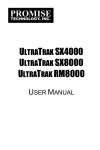
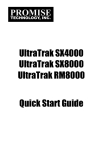
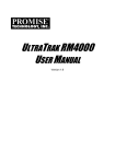
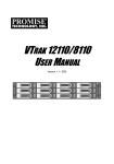
ULTRATRAK RM15000
QUICK START GUIDE
Version 1.0
UltraTrak RM15000
Copyright
© 2003, Promise Technology, Inc.
Copyright by Promise Technology, Inc. (Promise Technology). No part of this
manual may be reproduced or transmitted in any form without the expressed,
written permission of Promise Technology.
Trademarks
Promise, and the Promise logo are registered in U.S. Patent and Trademark
Office. All other product names mentioned herein may be trademarks or
registered trademarks of their respective companies.
Important data protection information
You should back up all data before installing any drive controller or storage
peripheral. Promise Technology is not responsible for any loss of data resulting
from the use, disuse or misuse of this or any other Promise Technology product.
Notice
Although Promise Technology has attempted to ensure the accuracy of the
content of this manual, it is possible that this document may contain technical
inaccuracies, typographical, or other errors. Promise Technology assumes no
liability for any error in this publication, and for damages, whether direct, indirect,
incidental, consequential or otherwise, that may result from such error, including,
but not limited to loss of data or profits.
Promise Technology provides this publication “as is” without warranty of any kind,
either express or implied, including, but not limited to implied warranties of
merchantability or fitness for a particular purpose.
The published information in the manual is subject to change without notice.
Promise Technology reserves the right to make changes in the product design,
layout, and driver revisions without notification to its users.
Contents
Step 1: Unpack the UltraTrak ............................................................................... 3
Step 2: Placement of your UtraTrak ..................................................................... 4
Step 3: Install Hard Drives.................................................................................... 5
Step 4: Connect the SCSI Cables ........................................................................ 9
Step 5: SCSI Termination................................................................................... 10
Step 6: Connect the Power ................................................................................ 11
Step 7: Enter the Password................................................................................ 13
Step 8: Assign a SCSI ID ................................................................................... 13
Step 9: Configure the UltraTrak....................................................................14
Step 10: Partition and Format the Array ........................................................14
Frequently Asked Questions .............................................................................. 15
2
Quick Start Guide
Step 1: Unpack the UltraTrak
Open the UltraTrak box and carefully remove the UltraTrak unit and accessories
from the box. The UltraTrak and accessories include the following items:
•
•
•
•
•
•
•
•
•
•
•
UltraTrak RM15000 Unit
Quick Start Guide
(2) Enclosure keys
Null Modem Cable
SCSI Terminator
Set of rackmount ears (brackets)
and screws
External LVD SCSI cable
(15) Screw sets for hard drives
(2) 1.5m power cords
(4) Rubber feet
CD with WebPAM Software,
WebPAM User Manual,
UltraTrak RM15000 User Manual,
RAID Console Driver and
Product Catalog
Note
The Web-Based Promise Array Management (WebPAM)
software provides monitoring and maintenance of your RAID
through a graphic user interface (GUI) on your PC.
Install WebPAM from the CD that comes with UltraTrak. You can
also download it from the Promise website (www.promise.com).
WebPAM will manage one UltraTrak system per PC via RS232
serial port or multiple UltraTrak systems via SCSI bus.
3
UltraTrak RM15000
Step 2: Placement of your UltraTrak
The UltraTrak may be installed in any convenient location within the LVD SCSI
cable length distance of the host system. The UltraTrak RM15000 is designed
specifically for rackmount installation but may also serve on a bench top as well.
The UltraTrak RM15000 installs directly to the rack with or without a shelf.
Assemble the Mounting Brackets on each side of the RM15000 and set the unit
into the rack.
Vertical Rack Post
SEL
UltraTrak RM15000
EXIT
Rackmounting Shelf (optional)
Figure 1.
Rackmounted RM15000
4
Quick Start Guide
Step 3: Install Hard Drives
Before using the UltraTrak you must first populate it with ATA hard drives. The
UltraTrak RM15000 can support up to fifteen disk drives and provide the
configurations listed below.
Number of Hard Drives
RAID
Configuration
Minimum
Maximum
JBOD (Single Drive)
1
15
RAID 0
2
15
RAID 1
2
2
RAID 3
3
15
RAID 5
3
15
RAID 0+1
4
14
RAID 30
6
15*
RAID 50
6
15*
* When a RAID 30 or 50 array has an odd-number of
disks, it cannot be converted to another RAID level.
.
Caution
You may mix manufacturer type and drive size – however, best
performance is achieved when you populate the array with
identical models. For different drive sizes, the arrays will use the
common disk size.
Warning
The electronic components within the UltraTrak disk array are
sensitive to damage from Electro-Static Discharge (ESD).
Appropriate precautions should be observed at all times when
handling the array or its subassemblies.
Caution
Before installing a new hard drive, be sure the jumpers on the
new hard drives are set for single, cable-select or master
operation. Consult the drive manual for the proper settings.
5
UltraTrak RM15000
Unlocked
Locked
Front Panel Lock
Figure 2.
UltraTrak Front Panel Access
Drive Latch
Figure 3.
Front Panel
H Disk
dl Drive Access
UltraTrak RM15000
6
Quick Start Guide
Install new hard drives into the UltraTrak by doing the following:
1. Unlock and open the Front Panel Door (see Figure 2) on the UltraTrak.
2. Pull the Drive Carrier Latch Handle and remove an unused Drive Carrier
(see Figure 3) from the UltraTrak. Begin at the left (Drive 1) and work
toward the right (Drive 15).
3. Carefully lay the hard drive into the drive carrier, with the drive’s connectors
facing the carrier’s connectors.
4. Slide the hard drive so the drive’s ATA connector fits into the carrier’s ATA
connector.
5. Attach the Drive Carrier power cable to the hard drive (see
Figure 4).
6. Lower the hard drive into the Drive Carrier so that the screw holes on the
7.
bottom line up.
Insert screws through the holes in the Drive Carrier and into the bottom of
the hard drive. Snug each screw. Be careful not to over tighten.
Power Connector
Hard Drive
Mounting Holes
(total of 4)
ATA Connector
Handle
Figure 4.
Insert the carrier into the
chassis this way.
Drive Carrier
7
UltraTrak RM15000
Important
Be sure each drive is securely fastened to its carrier. Proper
installation ensures adequate grounding and minimizes vibration.
Do not install drives with fewer than four screws.
8.
9.
Slide the assembled Drive Carrier back into the chassis and press the
handle forward to lock the Drive Carrier.
Repeat steps 2 through 8 until all of your hard drives are installed.
Channel 1
Figure 5.
Channel 15
Drive Channel Numbers
Caution
If you plan to operate your UltraTrak with fewer than 15 hard disk
drives, install all 15 Drive Carriers into the enclosure, even if they
are not holding a drive.
Important
The Drive Carrier Handle must be locked or the disk drive will
not power up.
8
Quick Start Guide
Step 4: Connect the SCSI Cables
Installation of the UltraTrak disk array is very similar to the installation of a
standard SCSI drive. The SCSI connector accepts the standard 68-pin High
Density LVD SCSI connector used on most LVD SCSI devices. Refer to your
system and/or SCSI host adapter manual for additional installation procedures
that may apply to your system or host adapter.
SCSI Input
Connector
Serial (DB-9)
Connector
FAN1
FAN3
FAN2
SCSI IN
SCSI IOUT/TERM
COM
SCSI Output
SCSI Cable from
Connector
Host SCSI Port
Figure 6.
Back of UltraTrak RM15000
Serial (RJ-45)
Connector
Caution
To prevent possible damage to the array or system, ensure that
system power is OFF before connecting the cables.
Caution
Use only externally shielded LVD SCSI cables.
Do not use internal flat ribbon cables for an external SCSI
application.
9
UltraTrak RM15000
Step 5: SCSI Termination
Correct SCSI termination procedures require that the last device on the SCSI bus
be terminated. If the last device is not terminated, or if a device other than the last
is terminated, erratic SCSI bus timeouts may occur. When installing the UltraTrak
RM15000 on a SCSI bus with other devices, be sure to observe this rule with all
devices on the SCSI bus. Consult your system and/or host adapter manual for
additional information on correct termination procedure.
Caution
Proper termination and SCSI-3 compliant cables are required for
the system to operate correctly. An external SCSI terminator and
a SCSI-3 compliant cable are included with the UltraTrak
RM15000.
SCSI Terminator
When the UltraTrak is the last SCSI device in the chain you must install the
Promise-supplied (or equivalent) external SCSI terminator on the SCSI Output
Connector. See Figure 7.
FAN1
FAN3
FAN2
SCSI IN
SCSI IOUT/TERM
SCSI Terminator
Figure 7.
COM
SCSI Output
Connector
SCSI Terminator Installation
10
Quick Start Guide
Step 6: Connect the Power
UltraTrak systems will operate on either 115 volts AC or 230 volts AC. The
RM15000 includes two replaceable power supply modules with autosense
voltage selection and Power Factor Correction (PFC).
Main Power Switch
OFF
ON
Power
Connectors
Figure 8.
Power Connections and Switch
Plug the UltraTrak and switch the power on. The main power switch is located on the
back of cabinet.
11
UltraTrak RM15000
When the power is switched on, the LEDs and LCD screen on the front of the
UltraTrak will light up.
Disk Drive LED View Ports
SEL
EXIT
LED Display
LCD Display
UltraTrak Displays
Figure 9.
The UltraTrak spins up the disk drives sequentially in order to equalize power draw
during start-up. After a few moments the LCD should display the following message:
NO ARRAY IS DEFINED
30°C/86°F 4500RPM
The front panel interface for the UltraTrak consist of following items:
Liquid Crystal Display
Power
Status
SEL
Select
Up
Down
Figure 10.
SCSI
EXIT
Exit
UltraTrak Front Panel Display and Controls
12
Quick Start Guide
Step 7: Enter the Password
You are prompted to enter the correct password each time you access the
UltraTrak Configuration mode. A password consists of four digits. The default
password is 0000.
PLEASE ENTER PASSWORD:
0000
The active password digit is marked by
an underscore.
Password entry begins with the left-most digit. You must enter the proper value
before proceeding to the next digit. You change the value of the active password
digit by pressing either the T button or the S button. The T button increments
the digit downward (as, 0, 9, 8, 7 …). The S button increments the digit upward
(as, 0, 1, 2, 3 …).
Press the SEL button to proceed to the next digit or to submit the password if you
have just entered the last digit. You are given access to the Configuration menu if
you entered the password correctly.
Step 8: Assign a SCSI ID
Each device on a SCSI chain must have a unique ID. The default SCSI ID setting
of the UltraTrak is 0. If you need to change the SCSI ID setting of the UltraTrak,
do the following:
1. From the Idle mode display, press the SEL button on the front panel.
2. Press T button once to select Configuration, then press SEL button.
3. Enter the password at the prompt.
4. At the Configuration menu, use the T button to select Configure SCSI, and
then press the SEL button. (See page 64 in the UltraTrak User Manual for
more details.)
5. At the Configure SCSI menu, use the T button to select the SCSI ID, and
then press the SEL button.
6. At the SCSI ID menu, use the S and T button to select the SCSI ID
number, and then press the SEL button.
7. Press the EXIT button until you return to the Idle mode.
13
UltraTrak RM15000
Step 9: Configure the UltraTrak
Following are the steps needed to create an array and get your UltraTrak running
quickly. We’re using the automatic setup feature here, but you may also set the
array up manually if you wish. Refer to the UltraTrak User Manual for details
regarding the manual setup procedure.
1. From the Idle mode display, press the SEL button on the front panel.
2. Press T button once to select Configuration, then press SEL button.
3. Enter the password at the prompt (see “How do I Enter a Password” on
page 15 of the UltraTrak User Manual).
4. At Configure Array, press SEL.
5. Auto Array Setup should be selected, press SEL.
If the message “*No Free Disk” appears, it means that an array has already
been configured. If you wish to re-create a new array, then you need to first
delete the existing array before you can proceed. See Delete Array on page
53 of the UltraTrak User Manual for more details.
Use the S and T button to select the proper RAID level for your array,
press SEL to choose the selected RAID level. See page 21 of the UltraTrak
User Manual for help in choosing the proper RAID level.
7. Press SEL to create the array or press EXIT to cancel.
8. If you elected to create the array then you should see the message “Array
has been created.”
You have successfully created an array.
6.
Note
Depending on the size of your array, RAID levels 1, 3, 5, 0+1, 30
and 50 may take a while to initialize.
Step 10: Partition and Format the Array
Like any other type of fixed disk media in your system, a RAID array must also be
partitioned and formatted before use. Use the same method of partitioning and
formatting on an array as you would any other fixed disk.
Depending on the operating system you use, there may or may not be various
capacity limitations applicable for the different types of partitions.
14
Quick Start Guide
Frequently Asked Questions
How do I enter the password?
You are prompted to enter the correct password each time you access the
UltraTrak Configuration mode. Password entry begins with the left-most digit.
You must enter the proper value before proceeding to the next digit. Change
the value of the active password digit by pressing either the T button or the
S button. The T button increments the digit downward (as, 0, 9, 8, 7 …). The
S button increments the digit upward (as, 0, 1, 2, 3 …). Press the SEL button
to proceed to the next digit or to submit the password if you have just entered
the last digit. You are given access to the Configuration menu when the
password is entered correctly.
What kind of hard drives can I use for an UltraTrak array?
You can use any Ultra ATA/133/100/66 hard drive(s) to create arrays on the
UltraTrak. You should use matching drives for multiple-drive arrays to
maximize capacity usage as well as performance.
How do I learn more about configuring the UltraTrak?
Refer to the UltraTrak User Manual. That manual contains detailed
information regarding configuration, troubleshooting and maintenance for your
UltraTrak.
I installed a new hard drive. Why doesn't it power up?
The drive carrier handle must be locked in order for the hard drive to receive
power. Be sure to slide the drive carrier all the way into the UltraTrak, then
gently press handle toward the carrier to be sure it locks.
Do I have to use the LCD panel and buttons on the UltraTrak to
create my RAID array?
No. You can also use the Web-Based Promise Array Management (WebPAM)
software. WebPAM allows you to create, monitor and maintain your RAID on
your PC though a web browser. A copy of WebPAM is on the software CD
that came with your UltraTrak and it is also downloadable from the Promise
website at www.promise.com.
15
UltraTrak RM15000
16