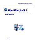
1
DC and DCC Operation of
Atlas Gold Series HO Scale Dash
8-40C/CW Diesel Locomotives
equipped with QSI Quantum
Titan Sound-Decoders
11 June 2014, Version 1.1
for QSI Firmware Version 9
Quick Start Guide for DC and DCC Operation of Atlas Gold Series HO-Scale GE
Dash 8-40C/CW Locomotives Equipped with QSI Quantum Titan Sound-Decoders
Congratulations on your purchase of an Atlas Master™ Gold Series HO-scale model of a GE Dash 840C/CW locomotive that is factory-equipped with a QSI Quantum Titan sound-decoder. This sounddecoder provides the highest quality sound plus state-of-the art motor control. Your locomotive can run
on either conventional DC (with limited features) or on NMRA Digital Command Control (with full
features).
This Quick Start Guide describes the basic features of the Quantum Titan sound-decoder when the
locomotive is operated on DC or DCC power. For a more complete description of both DC operation and
DCC operation, you can download the Atlas User Manual (Reference [1]) for this locomotive
User Manual: DC and DCC Operation of Atlas Gold Series Diesel Locomotives equipped with
QSI Sound-Decoders (Quantum™, Quantum Titan™, or Quantum Titan™ with ET), Version 6.10,
November 27, 2013 (or later)
from the Atlas website:
http://www.atlasrr.com/
by choosing Support, DCC Support, and then double clicking on the name of the document that you want
to download. This User Manual covers Atlas Gold Series locomotives with QSI firmware Versions 7, 8,
and 9. The sound-decoder in your MP15DC locomotive is a QSI Quantum Titan with Version 9 firmware.
DC Operation of your Atlas HO-scale Gold Series General Electric
Dash 8-40C/CW Locomotive
Using a standard variable-voltage DC power pack, turn the DC throttle up slowly until you begin to hear
locomotive sounds (around 4.5 volts). At DC track voltages between 4.5 and 8.5 volts, you will hear Start
Up sounds, and the Front and Rear Headlights will turn On in their Dim states. You must turn up the
throttle voltage up to a higher setting than you would to make a non-sound locomotive begin to move
(about 8.5 volts) before the Quantum-Titan-equipped locomotive starts to move. The locomotive starts
out moving slowly due to built-in inertia from the Back EMF motor control (used in Regulated Throttle
Control). The headlight in the direction of movement will turn from Dim to Bright; the headlight facing the
opposite direction will be Dim.
On a DC-powered layout, an Atlas HO-scale Gold Series Dash 8-40C/CW locomotive will automatically
produce sounds that are appropriate for its current state of operation. For example, the Brake Squeal
sounds play when the locomotive grinds to a halt. It is possible to trigger certain individual sounds (such
as the Horn or Bell) manually with a standard model railroad DC power pack.
•
Blowing the Horn on DC
-
-
To turn on the Horn while the locomotive is moving, flip the direction switch quickly to its
opposite position (e.g., if the direction switch is set for the locomotive to move Forward, move it
to the Reverse position). If you flip the direction switch too slowly from one position to the other,
you can momentarily lose power while the switch moves through its center position.
The locomotive will NOT change direction when you blow the Horn
Leave the direction switch in the opposite position until the Horn has sounded for as long as you
want it to sound. Then to shut off the Horn, flip the direction switch back quickly to its original
position.
2
•
Ringing the Bell on DC
-
-
Turn the Bell on with a Quick flip-and-back operation of the direction switch. The Bell will stay
on until you do another Quick flip-and-back operation of the direction switch to turn it off, or if
you interrupt the track power
Turn the Bell off with a second Quick flip-and-back operation of the direction
Note: You can turn the Bell on and leave it on while you operate other functions on the locomotive.
Note: Depending on the particular Bell that you select, it can have a slow start up effect where the pneumatic
clapper gradually gains power until it starts to strike the bell.
Note: When you turn the Bell off, it will continue ringing briefly with less and less volume as the pneumatic
clapper slows down, just like the prototype.
Note: If you do a Slow flip-and-back operation, you will get a short Horn hoot instead of the Bell.
Note: If you try to do a very short Horn blast using a Quick operation, you will activate the Bell instead
•
Controlling Other Sounds
If you already have a Quantum Engineer Controller (no longer available from Atlas), you can use it to
control additional sounds and other features (e.g., dimming headlights) on an analog (DC-powered)
layout. However, if you don’t have a Quantum Engineer and you wish to have manual control of
sounds beyond the bell and horn, but do not wish to invest in a Standard (full-featured) DCC System,
Atlas suggests that you consider purchasing a Basic DCC System which will allow you to control
many or all of the available sounds and other features in your Gold Series locomotive and also in any
other locomotive that is equipped with a DCC sound-decoder (from any sound-decoder
manufacturer). In spite of having all this extra capability, Basic DCC Systems are essentially as
simple to operate as a DC power pack. Currently available Basic DCC Systems include:
- NCE DCC Twin,
- MRC Prodigy Explorer DCC,
- MRC TECH 6 Sound Controller 6.0 (usable in smaller scales, but primarily intended for O-scale
and larger).
•
Modifying Analog Operational Parameters
One can change certain operational characteristics of the locomotive when it is operating on DC
power. Depending on the parameter(s) to be changed, parameter modifications are done in one of
two ways:
- Analog programming: Reference [2] lists the parameters that can be programmed by using the
direction switch of a standard DC power pack (or the QSI Quantum Engineer) and describes
how to do this programming.
- DCC programming: Other parameters that affect analog operation are programmed with the
same programming of DCC CVs (Configuration Variables) that is used to make the equivalent
modification for DCC operation. See Reference [3] for details. However, a Standard (fullfeatured) DCC System, as opposed to a Basic DCC System, may be needed to make some or
all of these changes.
3
DCC Operation of your Atlas HO-scale Gold Series General Electric
Dash 8-40C/CW Locomotive
•
DCC Functions Available in Atlas HO-Scale Gold Series GE Dash 8-40C/CW
Locomotives
The QSI Quantum Titan sound-decoder provides a number of different DCC functions that can be
triggered by pressing the appropriate key (e.g., press the “5” key to trigger DCC Function #5) on your
DCC controller. The following table lists the DCC functions available in the QSI Quantum Titan
sound-decoder installed in Atlas Gold Series HO-scale Dash 8-40C/CW locomotives.
DCC Function Key Operation for Atlas HO-scale Gold Series Dash 8-40C/CW Locomotives
Function
Key
FL(f)
Forward or Reverse (FWD or REV)
Neutral (either NFF or NFR)
F1
F2
F3
Headlight, Rear Headlight, and Hazard Light
(directional lighting On or Off)
Headlight, Rear Headlight, and Hazard Light
(directional lighting On or Off)
Bell On/Off
Horn or Horn with Doppler Effect
Coupler Crash/Coupler Fire
Headlight, Rear Headlight, and Hazard Light
(directional lighting On or Off)
Headlight, Rear Headlight, and Hazard Light
(directional lighting On or Off)
Bell On/Off
Horn
Coupler Arm (Enable) or Coupler Fire
F4
F5
Diesel Fans and Louvers On/Off
1
Dynamic Brake function On/Off
Diesel Fans and Louvers On/Off
Dynamic Brake function On/Off
(in Disconnect state only)
F6
F7
Doppler Shift (single-press F6)
Squealing Brakes/Flanges and Air Brakes
Locomotive Start Up (double-press F6)
Diesel: Long Air Let-off
F8
F9
Audio Mute On/Off
Heavy Load On/Off (single-press F9)
F10
Status Report (speed in SMPH )
Audio Mute On/Off
Advance Shut Down State: (Disconnect,
2
Standby, Total Shut Down) (double-press F9)
Status Report (Loco DCC address, etc.)
F11
Alternate Horn Selection (Titan only) or
Number Board or Marker Lights On/Off
4
Automatic Cab Lights On/Off
System Volume Decrease (Titan only)
System Volume Increase (Titan only)
Grade Crossing (Titan only)
Short Air Let-off
FL(r)
i
F12
F13
F14
F15
F16-F25
F26
F27
F28
3
2
Alternate Horn Selection (Titan only) or
Number Board or Marker Lights On/Off
Automatic Cab Lights On/Off
System Volume Decrease (Titan only)
System Volume Increase (Titan only)
Short Air Let-off
Fuel Loading Scenario (Titan only)
Maintenance Scenario (Titan only)
Water Loading Scenario (Titan only)
Reference [1] explains the operation of DCC functions F1 to F28 in more detail.
1
Dynamic brakes cannot be turned on in Forward or Reverse unless the locomotive is moving over 9 smph.
Entering a Shutdown state may sometimes require a triple press of F9.
3
SMPH = Scale Miles Per Hour
4
Automatic cab lights are not used in Atlas Gold Series locomotive equipped with QSI sound-decoders.
2
4
Default Headlight and Ditch light Operation in Atlas HO-scale Gold Series Dash 8-40C/CW
Locomotives
The following table describes the behavior of the Front and Rear Headlights and the Ditch Lights (when
equipped) of Atlas Gold Series Dash 8-40C/CW locomotives. Please note that Ditch Lights are included
only on Dash 8-40CW locomotives; Dash 8-40C locomotives do not have Ditch Lights.
Light
Front Headlight
Rear Headlight
Ditch Lights
Forward
On
Dim
On or flashing
Neutral from Forward
Dim
Dim
Off
Reverse
Dim
On
Off
Neutral from Reverse
Dim
Dim
Off
The Ditch Lights will flash alternately when the locomotive is moving forward and the Horn is being
blown. When the locomotive is first powered up, you may need to press the F0 (or Headlight) key on
your DCC system one or two times to turn on the directional Front or Rear Headlight.
•
DCC Programming Considerations
-
Programming Locations
Most DCC systems allow you to program a Configuration Variable (CV), such as the DCC
address of a locomotive, in either of two places:
o On a special section of track not connected in any way to your layout and called the
Program Track. (In DCC terminology, programming locomotives on the program track is
called Service Mode Programming.)
o Anywhere on the Main Line (regular track) of your layout. [In DCC terminology,
programming a locomotive on the main line of your layout is called either Programming on
the Main (POM) or Operations Mode (Ops Mode) programming.]
In most cases, programming the QSI Quantum Titan decoder installed in your GE Dash 840C/CW locomotive on the program track requires that a Program Track Booster be installed
between the program track output of your DCC system and your physical program track. Atlas
recommends the PTB-100 Program Track Booster from SoundTraxx.
-
Programming a New DCC Address for Your Locomotive
The decoder in every Atlas Gold Series locomotive comes from the factory set to use the short
address “3.” However, in order to control (independently) several locomotives on the same track
at the same time, it is necessary that each locomotive have a unique DCC address. A convenient
choice for the DCC address is the road number printed on the side of the locomotive’s cab.
Frequently, the number on the side of the cab is a 3- or 4-digit number, which is treated in DCC
as a Long (or 4-digit) Address.
If your DCC system allows you to program 4-digit addresses on the main line (many DCC
systems do), Atlas recommends that you take advantage of this capability by programming the
address of your Gold Series locomotive on the main line using Operations Mode (Ops Mode)
programming.
Although DCC systems differ in how (or if) they support programming of 4-digit addresses on the
main line, the following technique must be used with a number of DCC systems commonly sold
in North America:
o NCE: all NCE DCC systems
o Digitrax: all Digitrax DCC systems except for Zephyr and Zephyr xtra,
2
o MRC: Prodigy series [Advance, Advance (i.e., Advance Squared), Wireless, or Express].
5
Follow These Steps to Program a New 4-digit Address on the Main Line:
1. Operate the locomotive on the main line using its current DCC address.
2. If you cannot determine the current DCC address of the locomotive, transfer the locomotive
to a DC or DCC powered track, and reset the Quantum System decoder by following either
the DC or the DCC magnetic wand reset procedures given at the end of this Quick Start
Guide. After completing the reset, make sure that you can operate the locomotive using
the default DCC address “3.”
3. Disable verbal announcements by using Operations Mode programming to set CV62
= 0. Consult your DCC system manual for an explanation of how to program CVs. Since
you have just disabled verbal announcements, you will not hear any verbal confirmation of
the value of 0 that you just wrote into CV62.
4. Follow the procedure in your DCC system manual for programming a new Long Address
using Operations Mode programming on the main line. After you have completed setting
the Long Address, make sure that your DCC system has activated this Long Address, i.e.,
it has set CV29 to a value that supports 4-digit addresses (e.g., 34 or 38). In particular, if
you have a Digitrax DCC system that has a DT402 or DT400 walk-around throttle, be
certain to press the “Y+” key IMMEDIATELY after you see “Ad4on?=y” displayed on the
throttle screen.
5. Change your DCC system from its configuration for Operations Mode programming to its
configuration for running a locomotive on the main line (if the DCC system doesn’t perform
this reconfiguration automatically).
6. Verify that the locomotive can operate on the main line using its new 4-digit address. If the
locomotive doesn’t operate on the address that you just programmed, it may be worthwhile
to verify that CV29 was programmed correctly. To verify the value of CV29, do these
checks:
a. Set your DCC system to run a loco with address “3” (or whatever 2-digit address
you last used)
b. If your locomotive runs on address 3, program CV29 = 38 (use CV29 = 34 instead,
if you don’t want the locomotive to run on DC) and see if the loco now runs on the
4-digit address that you have just programmed.
7. If the locomotive responds properly to the new address, re-enable verbal announcements
by using Operations Mode programming again to set CV62 = 1. In this case, you will hear
verbal confirmation of the CV62 value of “1” that you just entered since you have just reenabled verbal announcements.
If your DCC system is NOT one of the DCC systems listed at the bottom of page 5, refer to Table
[1]
6 in the User Manual for the proper 4-digit address programming procedure to use (instead of
the procedure described above). Detailed information on each of these alternate address
programming procedures is included in the User Manual.
• Resetting your Locomotive to Factory Default Values Using the
Magnetic Wand (resets all Analog and DCC parameters)
Resetting the firmware in the Quantum or Quantum Titan sound-decoder to its factory-built
configuration can resolve many problems that sometimes occur with firmware-controlled electronics.
In fact, we have found at Atlas that at least 20 to 25 percent of the problems with the Gold Series
locomotives that we receive for repair can be resolved simply by resetting the sound-decoder.
Hence, the very first step you take to resolve a problem should be to reset the Quantum Titan sounddecoder in your locomotive.
6
There are two ways to reset the parameters of a Quantum, Quantum Titan or Quantum Titan with ET
sound-decoder (1) the DCC-only reset described in Section 4.2.6 of the Atlas User Manual[1] which
resets only the DCC CVs and (2) the magnetic wand reset described here that resets both DCC CVs
and analog parameters. Since a number of parameters (e.g., sound volumes) are shared between
DC and DCC operation, the magnetic wand reset does a better job of resetting the decoder to its
original factory configuration than does the DCC-only reset. Hence, Atlas recommends resetting
using the magnetic wand whether your locomotive is normally operated on DC or on DCC.
Every Atlas locomotive equipped with a QSI sound-decoder has a magnetic reed switch located
directly under the top of the plastic shell. This switch can be activated by the Magnetic Wand (the Tshaped object packed with your locomotive) without having to disassemble the locomotive. Resetting
with the magnetic wand can be done on either a DC-powered track or a DCC-powered track.
However, the procedure differs, depending on whether the track has DC or DCC power.
The following items are needed in order to do a magnetic wand reset.
ITEMS REQUIRED FOR MAGNETIC WAND RESET
1. The Gold Series locomotive that you wish to reset
2. The magnetic wand (packed with your locomotive)
3. The three photographs below that show where to place the
magnetic wand on the top of your locomotive.
4. Either a power pack with a variable-voltage DC output or a
DCC system
5. A DC- or DCC-powered track
Overall View
Top View
Side View
For older (pre-Titan) Atlas Gold Series locomotives, information equivalent to that contained in these three photos appeared on
page 3 of the 4-page locomotive information booklet that was packed with the locomotive .
7
Please note that, whether you are doing the reset on a DC-powered track or on a DCC-powered
track, you will be resetting ALL parameters, both DC and DCC, to their default values. The detailed
DC and DCC reset procedures are given below.
-
Magnetic Wand Reset Procedure for DC-Powered Track
1. Turn off all track power to your DC-powered layout.
2. Place your Atlas Gold Series sound-equipped locomotive on a section of track that is
powered by conventional DC.
3. Study the three photographs above to determine where to place the magnetic wand on the
top of your locomotive.
4. Place the Magnetic Wand over the reed switch area on the top of the locomotive at the
location determined in Step 3 and with the metal (shiny silver) part of the wand parallel
to the ties of the track and on or just above the top of the locomotive. The magnet
(the shiny silver cylinder) should be horizontal with one circular end pointing
towards one side (side NOT end) of the locomotive and the other end pointing
towards the other side. Keeping the wand in the small plastic bag in which it was
shipped prevents possible marring or scratching of the locomotive.
5. Slowly and gradually apply conventional DC power to your track until the track
voltage increases from 0 to approximately 8 to 10 volts. If the magnetic wand is in the
correct location (along the length of the locomotive) and with the silver part parallel to the
ties, the locomotive will not move, and there will be no sound until you hear “reset” spoken
in Step 6 (below).
6. While continuing to hold the magnetic wand on or just above the top of the locomotive,
keep increasing the track voltage slowly until you hear the word “reset” spoken from the
locomotive.
7. Caution: if you don’t hear the word “reset” spoken, your locomotive has NOT been reset.
8. Pull the Magnetic Wand straight up (away from the locomotive) immediately after you hear
“reset” so that the manual volume adjustment procedure (described in Section 6.2.2 of the
User Manual) is not activated.
-
Magnetic Wand Reset Procedure for DCC-Powered Track
1. Turn off all track power to your DCC-powered layout.
2. Set up the DCC system to run locomotive #3. (If you have to turn your DCC system On to
select locomotive #3, turn it Off after completing this step.)
3. Place your Atlas Gold Series sound-equipped locomotive on a section of track on the
layout.
4. Study the three photographs above to determine where to place the magnetic wand on the
top of your locomotive.
5. Place the Magnetic Wand over the reed switch area on the top of the locomotive at the
location determined in Step 4 and with the metal (shiny silver) part of the wand parallel
to the ties of the track and on or just above the top of the locomotive. The magnet
(the shiny silver cylinder) should be horizontal with one circular end pointing
towards one side (side NOT end) of the locomotive and the other end pointing
towards the other side. Keeping the wand in the small plastic bag in which it was
shipped prevents possible marring or scratching of the locomotive.
6. While you are holding the magnetic wand on the top of the locomotive in the position
described in Step 5, turn DCC power On for the track on which the locomotive is resting.
7. You should hear the word “reset” spoken, either immediately after you turn DCC track
power on or right after you start to advance the DCC throttle. Caution: if you don’t hear the
word “reset” spoken, your locomotive has NOT been reset.
8. Pull the Magnetic Wand straight up (away from the locomotive) immediately after you hear
“reset” so that the manual volume adjustment procedure (Section 6.2.2 of the User
Manual) is not activated.
After you have successfully completed either of these reset procedures (DC track power or DCC track
power), the locomotive will operate on DCC as loco #3
8
REFERENCES
[1]. User Manual: DC and DCC Operation of Atlas Gold Series Diesel Locomotives Equipped with
QSI Sound-Decoders (Quantum™, Quantum Titan™, or Quantum Titan™ with ET) Version 6.10,
27 November 2013 (or later).
This User Manual is downloadable from the Atlas Model website:
http://www.atlasrr.com/
by choosing Support, DCC Support, and then double clicking on the document that you want.
[2]. Quantum Analog Reference Manual Ver 4.0 (or later).
Available for download from the QSI Solutions website:
http://www.qsisolutions.com/
From the QSI Solutions Home Page, single-click on DOWNLOADS & MANUALS; scroll down
almost to the bottom (under the heading General): double-click on Quantum DC Analog
Reference Manual, Ver. 4.0 (or later).
[3]. NMRA DCC Reference Manual for QSI Quantum 3, 2, and 1 Equipped Locomotives, Version
5.1.0, February 4, 2013 (or later).
Available for download from the QSI Solutions website:
http://www.qsisolutions.com/
From the QSI Solutions Home Page, single-click on DOWNLOADS & MANUALS; scroll down
almost to the bottom (under the heading General): Just below the heading General, double-click
on Full DCC Reference Manual for All QSI Decoders.
9
Appendix: Body-Removal Instructions for Atlas
HO-Scale Dash 8-40C/CW Locomotives
When reading these instructions, please refer to the exploded diagram and parts list that was packed with
your Atlas HO Dash 8-40C/CW locomotive.
1. Take off the couplers first and then the chain. Do not remove the chain from the shell or the brake
cylinder
2. Remove the brake line from the one brake cylinder with the chain, then remove the brake cylinder
from the truck frame. Use a small screwdriver under the brake cylinder and lift upward slowly to
take it off. Just let the brake cylinder and the chain hang down from the still and careful of the
hook on the still it will break easily
3. Remove the fuel tank; the fuel tank is made up of two halves, and they pull apart right down the
middle.
4. Grab the bottom of the locomotive with one hand (where the fuel tank came off), and hold onto
the body shell with the other hand - starting at the rear of the locomotive near the radiator. With
your index finger on one side and your thumb on the other side of the body, pull upward and
wiggle slowly, being careful of the chain and handrails. The rear of the shell will start to come up,
and the front will probably also begin to come up. Sometimes you will have to pull and wiggle on
the front part of the body shell. To do this, put your thumb on one side and your index finger on
the other side just a little bit past the cab where it steps down on top of the locomotive between
the horn and the step on top of the shell. Just take your time and be careful of where you place
your fingers so you don’t break the chain (which is hanging loose), the handrails, or other detail
parts.
5. The shell goes back on the same way it came off, but be careful at the front end where you must
make sure that the cab is lined up with the frame. Make sure that the front is lined up first, and
then you can push down on the shell. Do not force the shell on.
6. If the shell is giving you a hard time, the front is not lined up with the frame. Try again and
remember to be careful of the chain and the handrails.
10
QS Industries License Agreement
These license terms are an agreement between QS Industries Inc. (QSI) and you.
if any. The terms apply to any QSI
•
Updates,
•
•
Network/Internal based services,
•
•
Support services,
•
•
Sound records,
•
They apply to any hardware, software, firmware, and any method by which you receive these items,
Firmware,
Software,
Hardware,
Anything incorporating any QSI technology and/or QSI intellectual property.
By using any of the items listed above (herein “PRODUCT”), you accept these terms. If you do not accept them, do not use this PRODUCT. Instead, return it the seller for a refund or
credit.
If you comply with these terms, you have the rights described below to use this PRODUCT.
1.
OVERVIEW:
a.
b.
c.
d.
e.
This QSI PRODUCT may include one or more of the following:
Sound Files: that incorporates sounds that may or may not been processed,
Software: the software includes control and operation processes, methods, documentation,
Firmware: code in QSI hardware product,
Hardware: Product produced or licensed by QSI, and/or
Anything that incorporates QSI technology and/or QSI Intellectual Property
2.
SCOPE OF LICENSE: The PRODUCT and incorporated intellectual property is provided with a license, not sold. This agreement only gives you limited rights to use the
PRODUCT. QSI reserves all other rights. This PRODUCT is copyrighted and incorporates QSI technology and/or Intellectual Property. Unless applicable law gives you more
rights despite this limited license, you may use the PRODUCT only as expressly permitted in this agreement. You may not
a.
Work around any technical limitation in the PRODUCT,
b.
Reverse engineer, decompile or disassemble the PRODUCT,
c.
Make copies of this PRODUCT ,
d.
Publish any portion of the PRODUCT for others to copy,
e.
Make a derivative work of this PRODUCT,
f.
Rent, lease or lend the PRODUCT, and
g.
Use any portion of PRODUCT together with an unauthorized product
QSI grants a limited license to use this PRODUCT for its normal intended purpose provided that
a.
b.
c.
d.
e.
f.
g.
h.
3.
Both the copyright notice and this limited permission notice appear in full,
The use of such PRODUCT is for personal non-commercial use,
This PRODUCT shall not be reproduced (in whole or in part in any manner) or posted anywhere (in whole or in part) on any computer, included in any computer
software, and/or broadcast in any media,
In the event that an injunction exists against QSI or an affiliate (any party working with QSI in any capacity), the aforementioned permission to use PRODUCT in
any manner is revoked,
In the event that any lawsuit is filed against QSI or an affiliate, the permission to use the PRODUCT by the plaintiff or any affiliates thereof and/or defendant or any
affiliates thereof in any manner is revoked,
No derivative works or modifications of any of the PRODUCT may be made,
Any oral or implied licenses are hereby revoked to the PRODUCT without a written agreement signed by both parties, and
Any other use of the PRODUCT requires express written permission signed by both parties.
SERVERABILITY: In the event that any portion of this agreement is found invalid, all other portions remain in effect
4.
AUTHORIZED PRODUCT: QSI Authorized Products are those products that are authorized by a mutual signed agreement with QSI.
5.
APPLICABLE LAW
a.
United States. If you acquire the PRODUCT in the United States, Oregon State law governs the interpretation of the agreement and applies to claims for breach
of it, regardless of the conflict of laws principals.
b.
Outside United States. If you acquire the product in any other country, the laws of that country apply
6.
INTELECTUAL PROPERTY NOTICE: The PRODUCT (Quantum Hardware, Software and Firmware) is covered by one or more U.S. Patent No. 4,914,431; 5,184,048;
5,267,318; 5,394,068; 5,448,142; 5,633,985; 5,832,431; 5,896,017; 5,940,005; 6,230,140 B1, 7,429,931 B1, 7,451,708 B1, 7,770,847 B1, 7,859,424 B2, RE42,284 E, 7.954,435
B2, 8,070,108 B2, 8,166,887 B2, 8,408,143 B2, and one or more patents pending. QSI PRODUCTS are copyrighted and registered.
7.
LIMTATION ON AND EXCLUSION OF DAMAGES. You can recover from QSI and its suppliers only direct damages up to the amount you paid for the PRODUCT. You
cannot recover any other damages including consequential, lost profits, special, indirect or incidental damages
This limitation applies to
•
Anything related to the hardware, software, firmware, sound files, services, content (including code) on third party internet sites or third party program and
•
Claims form breach of contract, breach of warranty, guarantee or condition, strict liability, negligence, or other tort to the extent permitted by applicable law
It also applies even if
•
Repair, replacement or a refund of the product does not fully compensate you for any losses or
•
QSI knew or should have known about or the possibility of the damages
Some states do not allow the exclusion or limitation of incidental or consequential damages so the above limitation of exclusion may or may not apply to you. They also may not
apply to you because your country many not allow the exclusion or limitation of inconsequential, consequential or other damages.
8.
NO OTHER RIGHTS: QS Industries, Inc. retains title and ownership of all Quantum Hardware designs, the Quantum Programmer™, associated operating Software/Firmware
code and PRODUCT. Except as stated above, this agreement does not grant you any rights to intellectual property rights and or Copyrights to the Quantum Software,
Firmware, Hardware or PRODUCT. The use of any trademarks or intellectual property as herein authorized does not give you any rights of ownership in that trademark or any
other Intellectual Property owned by QSI.
9.
LICENSE TERMINATION: If you breach any portion of this agreement (material and/or immaterial), your license is automatically terminated, without notice
© 2014 All rights reserved. Information in this publication supersedes that in all previous published material. The contents and the product it describes are subject to change without notice. QSI is a registered trademark of QSindustries, Inc. Quantum,
Quantum System, Sound-of-Power, Scale Sound, Regulated Throttle Control, and QARC are trademarks of QSindustries, Inc. NCE, Power Pro, and Power Cab are trademarks of NCE Corporation. Digitrax, Empire Builder, Super Chief, Zephyr, and Zephyr
Xtra are trademarks of Digitrax Inc. MRC, Prodigy Express, Prodigy Advance and Prodigy Advance2 , and Prodigy Wireless are trademarks of Model Rectifier Corporation. All other trademarks are the property of their respective holders. QSI makes no
representations or warranties with respect to this publication. In no event shall QSindustries, Inc. be liable for any damages, direct or incidental, arising out of or related to the use of this publication. Issued 06/2014
11