1
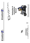
Traffic Safety
Corporation
In-Roadway Warning Lighting System
Power Adapter Installation and Owner’s Manual
Parallel Circuit Installation
www.xwalk.com
TSC Technical Support Center
888-446-9255
Tel: 916.394.9884
Fax: 916.394.2809
TSC-IM02
Rev. B
Released: 090908
Technical Support Center Reference Information
System Controller Part Number ______________________________________
Controller Serial Number ____________________________________________
Fixture Model Number ______________________________________________
Number of Fixtures _________________________________________________
Date of Shipment __________________________________________________
Retain this installation and user manual as a permanent record of your system
purchase and as a reference in the event that warranty service is required.
Register your system on-line.
TSC has provided a convenient and efficient way to register your new system on-line at
www.xwalk.com/registration. Registration is required within 1-Year of the date of shipment to qualify the
system for TSC’s 5-Year Limited System Warranty.
By registering your system with TSC, you will be recorded as the owner of the system. Your registration
with TSC:
Will serve as conformation of your system purchase and qualify your system for TSC’s 5-Year
Limited System Warranty.
Provide us with the information required for quick servicing of your requests.
Help us notify you of enhancements or modifications to your system.
Copyright © 2007 Traffic Safety Corp. All rights reserved. No part of this manual may be reproduced, scanned, or
distributed in any printed or electronic form without written permission from TSC.
2
Table of Contents
Introduction ………………………………………………………………... 4
Section 1 – General Information
A. Warranty Requirements …...…........……………..………...............………………..… 5
B. Installation Precautions and Recommendations ………………………………........…. 5
C. Technical Support Center Contact Information ………..……….……………….....…. 5
Section 2 – In-Roadway Installation
A.
B.
C.
D.
E.
F.
Placement of Fixtures ……………….....…………...…………….………………...…. 6
Drainage System Requirements ……………………..................................…………... 8
Drainage System Design ………………………………………..…………………...... 8
Base Can Installation – Core Drill and Saw Cut …………. ……………..………….... 9
Base Can Installation – Trench and Fill – Option 1 ………………………………...… 11
Base Can Installation – Trench and Fill – Option 2 ………………………….……...... 12
Section 3 – Electrical Installation
A.
B.
C.
D.
E.
Fixture Cabling …………….. …………………………….………………………...… 15
Fixture Connection ………………………………………..……………….. ………… 15
Activation Device Cabling ……………………………………...……..……..….……. 16
Power Adapter Connections ……………………………….……..…………………… 16
Power Adapter Configurations ……………………………….……..………………... 19
Section 4 – Maintenance
A.
B.
C.
D.
Fixture Shell …….……………..…………..……………………..………........………
Base Can …………….………………….…………………………………..…….……
Fixture Lens …………………………….………………………………….……..…....
LED Lamp ……………...…………….………………………………………....……..
22
22
22
22
Appendix
A. Required Information for System Warranty Registration ………….……………...….. 23
B. Limited System and Product Warranties ……………………….....……….………….. 24
C. Fixture Cabling Test ......................................................................................................... 24
D. Core Drill and Saw Cut Installation Pictures .................................................................... 25
E. Wiring Instructions for Advanced Activation Devices ..................................................... 27
3
Introduction
Traffic Safety Corporation’s In-Roadway Warning Lighting System is one of the most durable and
reliable lighting systems ever developed. To insure the integrity of the system over its lifetime the system
must be properly installed. Failure to install the system properly will negatively impact the performance
of the system, shorten its life and may void the manufacturer’s warranty.
The proper installation and operation of your system is our top priority. For that reason this installation
manual has been designed to guide you through each of the major steps of the In-pavement and electrical
installation of the system. We recommend that the manual be given to both the design engineer and the
installer of your system, well in advance of the actual installation.
The major steps covered in this manual include:
A. In-Roadway Installation
1. Placement of Fixtures
2. Drainage System Requirements and Design
3. Base Can Installation
B. Electrical Installation
1. Fixture Cabling and Connection
2. Activation Device Cabling
3. System Control Connection
Please call if you have any questions or concerns about the installation requirements, system set-up or
operation. Suggestions for improving our installation manual are welcomed. The TSC Technical Support
Center can be reached, toll-free, at 1-888-446-9255.
4
Section 1 – General Information
A. Warranty Requirements
TSC offers a 5-Year Limited System Warranty on its In-Roadway Warning Lighting System, the
industry’s longest warranty. In order to qualify for the warranty the following requirements need to be
met:
1. System must be installed properly. Failure to install the system properly may affect the
integrity of the system and shorten its life.
2. Use only the TSC supplied components shipped with your system. This is a matched
component system and the use of any other components may affect system performance or
damage the system.
3. Do not replace High Bright LED Arrays in the field. The long-life High Bright LED arrays are
replaceable only in the factory. Factory replacement includes overall fixture inspection,
replacement of the LED array(s), replacement of the gaskets and, or O-Rings, validation of
seal and LED burn-in.
4. The TSC system must be registered with TSC using the on-line system in order to activate
TSC’s 5-Year Limited System Warranty. The Information required for registration is listed in
Appendix C.
B. Installation Precautions and Recommendations
1. Verify that the drainage system is working properly by pouring water into the installed base can of each
fixture, and checking that the underlying drainage is absorbing the water. This should be done after the
core drilling or trenching, but before the fixture is installed and the concrete is poured. The water
absorption test is done prior to pouring concrete so that, if the drainage system is not performing
properly, it can be repaired without having to remove and then re-pour the concrete.
2. Base cans are shipped with a protective plywood cover, TSC’s Part# BA-PLCVR-3/4. The cover is
used to protect the flange ring and keep debris out of the base can during installation, whenever the
fixtures need to be removed for routine maintenance, during road resurfacing or during fixture shipment.
After installation, fixture covers should be marked, “DO NOT DISCARD”, and stored in a safe location
until needed.
C. Technical Support Center Contact Information
If You Have Any Questions or Concerns
Call TSC Technical Support Center
Before Proceeding
Open M-F, 8:00 am to 5:00 pm PST
Call Toll Free @ 1-888-446-9255
5
Section 2 – In-Roadway Installation
A. Placement of Fixtures
Refer to the design engineer’s drawings for recommended placement of fixtures. Orient the base cans
so that the conduit runs parallel to the direction of on-coming traffic. Many possible fixture configurations
are possible depending on the type of road that the crosswalk is being installed across. Typical layouts for
the more common installations are shown below:
Two Lane, One Way
Two Lane, Two Way
Two Lane w/Turn Lane
Four Lane, Two Way
6
Section 2 – In-Roadway Installation
A. Proper Placement of Fixtures
Four Lane, Two Way w/Turn Lane
Typical Fixture Layout for Two Lane Road
7
Section 2 – In-Roadway Installation
B. Drainage System Requirements
The truism that water and electricity don’t mix holds for In-Roadway lighting Systems. Roadway
pavement is subject to many sources of moisture. The most serious of which is ground water. The TSC
In-roadway lighting system is designed to prevent water and water vapor from making contact with
electrical conductors, contacts and connections. Fixtures used in the TSC system employ seals that
prevent moisture from entering the light fixture. The connectors used are waterproof and provide
connection between the fixture, and control system without fear of electrical shorting to ground. However,
water within the base cans, left for long periods of time, may create problems. Standing water in the base
can is especially undesirable in colder climates because of damage done when water freezes and expands.
To prevent problems caused by standing water in the base cans a proper drainage system must be
designed and tested prior to the electrical installation of the fixtures and pouring of concrete. Failure to
install a proper drainage system may result in damage to the system components.
C. Drainage System Design
A number of drainage system designs may be used to provide proper drainage for the TSC In-roadway
warning light system. Two types of drainage systems are typically used in the installation of the system:
•
Modified French Drain – This drain typically consists of a 1 1/2 inch diameter PVC
pipe discharging into a drain rock section, which is installed directly under the drain hole
of the base can. See Figures 1 & 2.
•
Piped Drain - This drain provides positive drainage from each base can through a pipe system
that carries any water that gets into the system off the edge of the street where it will drain into
an open ditch, storm drain system, or other drainage facilities that are available. See Figure 3.
If no existing drains are available, then an excavation can be made at the outside of the street
section and this excavation filled with drain rock. This will serve as a retention area for water
produced in the system and an area to allow for percolation of this water into the surrounding
ground.
Because local codes, soil conditions and weather conditions are unique to each location TSC will not
specify a drainage system for a specific installation. The typical installations described in the following
pages are provided as general guidelines and may not apply at your site location. Refer to the Design
Engineer’s drawing for the drainage system specified for your specific installation. If one has not been
prepared, ask the Design Engineer to prepare one before proceeding with the installation. If you, or the
design engineer, have any questions about the need for a drainage system, we urge you to contact the
TSC Technical Support Center, toll-free, at 1-888-446-9255.
8
Section 2 – In-Roadway Installation
D. Base Can Installation – Core Drill and Saw Cut (Figure 1)
1. Remove base can covers and store them in a safe location.
2. Begin the core drilling (typically 12 - 14 inch diameter and 23 - 31 inch deep) and saw cut process. Holes
should be drilled at fixture locations. Saw cuts should then be made to allow room for the fixture power cables
(typically 3½" deep x ½" wide). Saw cuts are made parallel to the direction of the pedestrian travel and in line
with the centers of the conduit holes.
3. In this installation, the base can fixture cable conduit holes will not be used with conduit. However, the
fixture cables will pass from the edge of the saw cut into these holes. The cables will be held in place and the
holes sealed with a sealing compound such as Dollie Duct Seal Compound, or equivalent.
4. Prepare the drainage system specified by the design engineer. With this type of installation it is impractical
to install a piped drain system. It is recommended that the modified French drain system is utilized. Refer to
figure 1.
5. Install the base can drain fittings provided into each base can drain hole. Run 11/2 inch size pipe,
Schedule 40 PVC, into the fittings of the base can. Pipe length should be cut so that the pipe, when positioned
over the drain, extends approximately 3 to 4 inches into the drain rock.
6. Suspend the base cans so they are level with the surface of the pavement. Base cans should be oriented so
that the fixture optics will be aligned parallel with the traffic lane. Use of mounting jigs is recommended for
proper alignment of base cans. Consult the design plans for the preferred method of base can suspension for
your installation.
7. Test the drainage system by pouring water into the installed base can at each fixture location. Pour enough
water to verify that the underlying ground is absorbing the water. If the base can is not draining properly,
modifications to the drainage system will be necessary. In this case consult with your design engineer before
proceeding. Once satisfied move on to the next step.
8. Install the fixture cables. Run fixture power cables to each base can, one black wire and one white wire to
each can. If grounding is required by local code, run an additional wire (green or blue) to each base can. The
ground wire can be attached to the base can using the ground strap provided at the bottom inside of each base
can.
9. Encase the base cans and drainage system in concrete. It is recommended that at least 6 inches of concrete
be used below the base. Fill saw cuts with Traffic Loop Sealant, or equivalent.
10. Remove mounting jig, clean out base can and replace protective plywood covers until are ready for
installation.
11. Your base cans are shipped with protective plywood covers, TSC's Part# BA-PLCVR-3/4. After installing
fixtures, be sure to mark these covers, "Do Not Discard", and save them for future use.
9
Section 2 – In-Roadway Installation
Figure 1: Base Can Installation – Core Drill and Saw Cut
12”
1.58”
8.84”
1.58”
1 1/2 " PVC
Notes
1. Drain rock shall be graded from 1 inch to ¼ inch.
2. Drain rock shall be encased in a filter fabric material to avoid soil infiltration into the
drain rock.
3. Recommended depth of drain rock unit varies dependent upon the type of existing
soils.
a. Where existing soils are granular and permeable the depth of the drain rock unit
can be limited to 1 feet.
b. Where existing soils are fine graded and have low permeability the depth of the
drain rock unit should be increased to 3 feet or greater to provide a reservoir for
short term retention.
4. Concrete shall be 3/8 inch maximum aggregate mix, use a minimum of seven sacks of
cement per cubic yard of concrete and poured from a height of approximately 5 inches
above the can. Concrete should only be poured from one side. Vibrate or rod concrete
to completely fill the area below and on all sides of the base can. When concrete is
visible on the side opposite the side that concrete is being from, pouring can commence
from alternate locations.
5. Abbreviations: Asphalt Concrete (AC), Aggregate Base (AB)
6. Drawing not to scale.
10
Section 2 – In-Roadway Installation
E. Base Can Installation – Trench and Fill – Option 1 (Figure 2)
1. Remove base can covers and store them in a safe location.
2. Begin trenching process. After trenching is completed along fixture locations, prepare the drainage system as
specified by the design engineer. Refer to figure 2.
3. Install the base can drain fittings provided into each base can drain hole. Run 1 1/2 inch size pipe, Schedule
40 PVC, into the fittings of the base can. Pipe length should be cut so that the pipe, when positioned over the
drain, extends approximately 3 to 4 inches into the drain rock.
4. Suspend the base cans so they are level with the surface of the pavement. Base cans should be, oriented so
that the fixture optics will be aligned parallel with the traffic lane. Use of mounting jigs are recommended for
proper alignment of base cans. Consult the design plans for the preferred method of base can suspension for
your installation.
5. Test the drainage system by pouring water into the installed base can at each fixture location.Pour enough
water to verify that the underlying ground is absorbing the water. If the base can is not draining properly,
modifications to the drainage system will be necessary. In this case consult with your design engineer before
proceeding. Once satisfied move on to the next step.
6. Install fixture cable conduit. Run 1 inch pipe size, Schedule 40 PVC, between each base can. PVC conduit
should fit snugly into the grommets located at each base can conduit hole. Complete installation by
runningconduit from the last base can in the system to the system controller, as specified by the design engineer.
7. Install the fixture cables. Run fixture power cables through the conduit into each base can, one black wire and
one white wire. If grounding is required by local code, run an additional wire (green or blue) through the conduit
to each base can. The ground wire can be attached to the base can using the ground strap provided at the bottom
inside of each base can. Refer to Section 3A.
8. Encase the base cans and drainage system in concrete. It is recommended that at least 6 inches of concrete be
used below the base.
9. Backfill the trench with specified material, compact and cover per the designer's specifications, taking care
not to damage conduit or drainage system.
10. Remove mounting jig, clean out base can and replace protective plywood covers until fixtures are ready for
installation.
11. Your base cans are shipped with protective plywood covers, TSC's Part# BA-PLCVR-3/4. After installing
fixtures, be sure to mark these covers, "Do Not Discard", and save them for future use.
11
Section 2 – In-Roadway Installation
Figure 2: Base Can Installation – Trench and Fill (Option 1)
12”
1.58”
8.84”
1.58”
1 1/2 " PVC
Notes:
1.
Drain rock shall be graded from 1 inch to ¼ inch.
2. Drain rock shall be encased in a filter fabric material to avoid soil infiltration into the
drain rock.
3.
Recommended depth of drain rock unit varies dependent upon the type of existing
soils.
a. Where existing soils are granular and permeable the depth of the drain rock
unit can be limited to 1 feet.
b. Where existing soils are fine graded and have low permeability the depth of
the drain rock unit should be increased to 3 feet or greater to provide a
reservoir for short term retention.
4. Concrete shall be 3/8 inch maximum aggregate mix, use a minimum of seven sacks of
cement per cubic yard of concrete and poured from a height of approximately 5 inches
above the can. Concrete should only be poured from one side. Vibrate or rod concrete
to completely fill the area below and on all sides of the base can. When concrete is
visible on the side opposite the side that concrete is being from, pouring can
commence from alternate locations.
5. Abbreviations: Asphalt Concrete (AC), Aggregate Base (AB)
6. Drawing not to scale.
12
Section 2 – In-Roadway Installation
F. Base Can Installation – Trench and Fill – Option 2 (Figure 3)
1. Remove base can covers and store them in a safe location.
2. Begin trenching process. After trenching is completed along fixture locations, prepare the drainage system
as specified by the design engineer. Refer to Figure 3.
3. Install the base can drain fittings provided into each base can drain hole. Suspend the base cans so
that they are level with the surface of the pavement and aligned parallel with the traffic lane. Use of
mounting jigs is recommended for proper alignment of base cans. Consult the design plans preferred method
of base can suspension for your installation.
4. Install drain conduit. Run 1 1/2 ", Schedule 40 PVC, from each base can fitting into the proper coupling
(right angle bend, T-adapter, etc.)Connect all couplings together using the proper length PVC pipe. Run the
end of the drain conduit into the drainage system, ditch, or leaching pit. The drainage conduit pipe should
have a slight negative slope.
5. Test the drainage system by pouring water into the installed base can at each fixture location. Pour
enough water to verify that the drainage system is absorbing the water. If the base can is not draining
properly, modifications to the drainage system will be necessary. In this case consult with your design
engineer before proceeding. Once satisfied move on to the next step.
6. Install fixture cable conduit. Run 1 inch pipe size, Schedule 40 PVC, between each base can. PVC
conduit should fit snugly into the grommets located at each base can conduit hole. Complete installation by
running conduit from the last base can in the system to the system controller, as specified by the design
engineer.
7. Install the fixture cables. Run fixture power cables through the conduit into each base can, one black wire
and one white wire. If grounding is required by local code, run an additional wire (green or blue) through the
conduit to each base can. The ground wire can be attached to the base can using the ground strap provided at
the bottom inside of each base can. Refer to Section 3A for details before proceeding.
8. Encase the base cans and drainage system in concrete. It is recommended that at least 6 inches of concrete
be used below the base.
9. Backfill the trench with specified material, compact and cover per the designer's specifications, taking
care not to damage conduit or drainage system.
10. Remove mounting jig, clean out base can and replace protective plywood covers until fixtures are ready
for installation.
11. Your base cans are shipped with protective plywood covers, TSC's Part# BA-PLCVR-3/4. After
installing fixtures, be sure to mark these covers, "Do Not Discard", and save them for future use.
13
Section 2 – In-Roadway Installation
Figure 3: Base Can Installation – Trench and Fill (Option 2)
12”
1.58”
8.84”
12”
1.58”
1.58”
8.84”
1.58”
1 1/2 " PVC
1 1/2 " PVC
Notes:
1. The 1 1/2 inch PVC drain conduit is
used to discharge water into the
existing drainage system, existing
ditches or if necessary a leaching
pit.
2. The leaching pit can consist of a 36
inch diameter drilled hole carried to
a depth of 6 to 10 feet and filled
with drain rock.
3. Abbreviations: Asphalt Concrete
(AC), Aggregate Base (AB), Slope
(S).
1 1/2" PVC
4. Drainage slopes of 1% are typical
5. Drawing not to scale.
6. Concrete shall be 3/8 inch maximum aggregate mix, use a minimum of seven
sacks of cement per cubic yard of concrete and poured from a height of
approximately 5 inches above the can. Concrete should only be poured from
one side. Vibrate or rod concrete to completely fill the area below and on all
sides of the base can. When concrete is visible on the side opposite the side
that concrete is being from, pouring can commence from alternate locations.
14
Section 3 – Electrical System Installation
A. Fixture Cabling
1. Using 10 AWG wire of appropriate type to meet local codes, pull one White (+12/24 VDC) and
one Black (Return) power wire to each fixture (parallel circuit). If local code requires grounding,
pull an additional green wire to each fixture.
Note: Red wire may be substituted for White wire in DC
circuits to reduce confusion between AC and DC circuits. Red
wire will then be connected to the white lead wire on pigtail.
2. If the system is +12/24 VDC, then cable may be installed directly into saw cut 2½ inch minimum
(typically 3½ inch) depth x 3/8 inch wide, instead of running the cable through conduit. Cable
should be stacked into the saw cut, held down to the bottom using a backing rod and sealed using
Bondo P606 or equivalent sealing compound. If using conduit pull cable through conduit. Ensure
that all wiring conforms to NEC, State, Local and other applicable codes.
3. Make a parallel circuit with 3M or similar waterproof connectors. At each fixture, using TSC’s
Part# CO-1051903021 pigtail connect the BLACK pigtail lead to the BLACK #10 AWG wire and
connect the WHITE pigtail lead to the WHITE #10 AWG wire. The use of drip-loops is
recommended.
Note: Before proceding to the next step check fixture cabling
using the fixture cabling test in Appendix C.
Note: Before inserting fixtures into sockets, test each fixture using the test
fixture socket and power plug cable supplied. The power plug plugs into
any standard 12 Volt Car Accessary socket. Each fixture is tested by inserting
its connector into the fixture socket.
B. Fixture Connections
1. Test each fixture using the fixture test cable supplied before inserting fixture into socket.
2. Using electrician’s tape, make three wraps around the pigtail connector and fixture plug.
3. Prior to bolting down the fixtures, coat the mounting flange of each base can with a marine grade
anti-seize grease, like Corrosion Block or equivalent.
4. Apply a marine grade anti-seize grease to the treads of the bolts that hold down the fixture.
5. Bolt the fixtures to the base cans using the stainless steel bolts provided.
15
Section 3 – Electrical System Installation
C. Activation Device Cabling
Follow separate installation instructions provide by TSC to connect activation device(s) provided with
the system.
D. Power Adapter Connection
If your system shipped with a controller other than the PA refer to its installation manual, otherwise
use the installation instructions for the PA provided in this section. Refer to the TSC wiring diagram
provided with your system. Directions for installation are provide below. Typical terminal configurations
are shown in part E of this section. Locate your configuration and refer to it during the installation of the
PA. If your system contains a push-button station with the "Talking Option" refer to the special installation
instructions provided with your system.
Interval
Timer
Flasher
Circuit
Breaker
PS2
Power Supply
PS1
Power Supply
TB3
Terminal
Block
TB1
Terminal
Block
TB2
Terminal
Block
Ground
Post
Configuration 7: 12 VDC Primary and Auxiliary Outputs
Push Button and Ped-X-Pad Activation
16
Section 3 – Electrical System Installation
1. Mount power adapter in its proper location, as specified in the design plans.
2. Make sure that the devices provided are rated for the output voltage level of the power adapter.
Caution: Devices are specifically matched to the output voltage
level of the control system. Use of any other type or quantity of
fixtures may damage the power adapter, fixtures or both.
3. Set the circuit breaker to OFF position.
Caution: Always ensure the system circuit breaker is in the
OFF position before servicing the system wiring.
4. Connect green or blue ground wire to system grounding post, as required by local code.
5. To provide maximum protection from surges, ensure that the system ground rod is tested and
provides less than 25 ohms to ground resistance.
6. Connect the power adapter to power source at the 120 VAC Input terminals. Black wire to Line
terminal and White wire to Neutral terminal.
7. Connect the IRWL parallel circuit wiring to (+/-) 12/24 VDC Output terminals with White wire to
+12/24 VDC and Black wire to -12/24 VDC.
Note: Red wire may be substituted for White wire in DC
circuits to reduce confusion between AC and DC circuits. Red
wire is connected to +12/24 VDC terminal block contact.
8. Connect basic push-button activation devices to the PB1 and PB2 terminals. If using a Talking/LED
Push-button Station or Ped-X-Pad activation device refer to wiring instructions in Appendix E.
9. If an AC auxiliary output device is provided:
a. Ensure that DC loads are not connected to the 120AC AUX output terminal.
b. Set the circuit breaker to the ON position and test the operation of the DC outputs before continuing.
c. After testing is completed, set the circuit breaker to the OFF position.
10. AUX Output Connection Options:
a. 120 VAC AUX Output Option: Connect 120 VAC auxiliary devices to 120 VAC AUX
Output terminals. Black wires to the Line terminal and White wires to the Neutral terminal.
b. 12 VDC AUX Output Option: Connect 12 VDC auxiliary devices to 12 VDC AUX Output
terminals. White wires to +12 VDC terminals and Black wires to -12 VDC terminals.
11. Ensure all wiring conforms to local code.
17
Section 3 – Electrical System Installation
12. Set the circuit breaker to ON position and test the operation of the AUX outputs.
Caution: Before turning circuit breaker to the On position
ensure DC load circuits are connected to the DC terminals and
AC load circuits are connected to the AC terminals. Connecting
a DC load to the AC terminals will damage the DC load device
and its wiring.
13. Adjust the interval timer on the Power Adapter panel for the desired activation period (1-99
seconds).
14. Test the system timing by triggering each activation device and monitoring the flashing fixtures
for the programmed activation period.
18
Section 3 – Electrical System Installation
E. Power Adapter (PA) Configurations
TB1
TB2
Configuration 1: TB1: 120 VAC Input; TB2: Push-button Activation, 12 VDC
Primary and Auxiliary Outputs
TB1
TB2
TB3
Configuration 2: TB1: 120 VAC Input; TB2: Push-button Activation, 12 VDC
Primary and Auxiliary
Outputs,2TB3: 120 VAC Auxiliary Output
Configuration
TB1
TB2
TB3
Configuration 3: TB1: 120 VAC Input; TB2: Push-button Activation, 12 VDC
Primary Output; TB3: 120 VAC Auxiliary Output
19
Section 3 – Electrical System Installation
TB1
TB2
TB3
Configuration 4: TB1: 120 VAC Input; TB2: Ped-X-Pad Activation; TB3: 12 VDC
Primary and Auxiliary
Outputs 4
Configuration
TB1
TB2
TB3
TB4
Configuration 5: TB1: 120 VAC Input; TB2: Ped-X-Pad Activation; TB3: 12 VDC
Primary and Auxiliary
Outputs;5TB4: 120 VAC Auxiliary Output
Configuration
TB1
TB2
TB3
Configuration 6: TB1: 120 VAC Input; TB2: Ped-X-Pad Activation; TB3: 12 VDC
Configuration
Primary Output;
TB4: 120 VAC6Auxiliary Output
20
TB4
Section 3 – Electrical System Installation
TB1
TB2
TB3
Configuration 7: TB1: 120 VAC Input; TB2: Ped-X-Pad Activation; TB3: Push-button
Activation, 12 VDC
Primary and7 Auxiliary Outputs
Configuration
TB1
TB2
TB3
TB4
Configuration 8: TB1: 120 VAC Input; TB2: Ped-X-Pad Activation; TB3: Push-button
Configuration
Activation, 12 VDC
Primary and8 Auxiliary Outputs; TB4: 120 VAC
Auxiliary Output
TB1
TB2
TB3
TB4
Configuration 9: TB1: 120 VAC Input; TB2: Ped-X-Pad Activation; TB3: Push-button
Activation, 12 VDC Primary output; TB4: 120 VAC Auxiliary Output
Configuration 9
21
Section 4 – Maintenance
A. Fixtures
Fixtures are made from corrosion resistant anodized aluminum or corrosion resistant stainless steel that
can withstand salt and other chemicals. Fixtures are rated to withstand static loads up to 44,000 lbs.
without sustaining permanent deformation or cracking of materials. Leads and gaskets are rated to
withstand up to 300 degrees F. Under normal conditions no maintenance is required except to periodically
check the integrity of the drainage system, periodic cleaning of the lenses and occasional factory
replacement of the LED lamp.
B. Base Cans
Traffic Safety fixtures are designed for minimum field maintenance. If properly installed, fixtures should
not require any maintenance. Fixtures subjected to standing water in the base cans for long periods of time
will eventually take in water, resulting in an electrical short and damage to the fixture. Furthermore,
standing water in the base can that is subject to cold temperatures may damage the base can, fixture and,
or connectors due to repeated expansion and contraction of the water as it freezes and melts. As part of a
maintenance program, fixtures should be checked every six months to ensure the integrity of the drainage
system. Any standing water should be removed immediately.
C. Lenses
The TS400, TS500 and TS600 series fixtures all feature a self cleaning lens design. If the fixtures are
installed properly cleaning will not be required for long periods of time. If needed, lens cleaning can be
done periodically using pressure or hand washing.
.
D. LED Lamp Replacement
The long lasting LED arrays have an estimated ten year average life expectancy. In order to keep the
fixture warranty in effect all LED lamp replacements are serviced at the TSC facility. At our facility we
complete a comprehensive inspection and evaluation of the fixture; replace the LED unit(s), replace the
sealing components, gaskets and, or O-Rings; verify the seal and burn-in the LED unit(s). A process is in
place to make the lamp replacement easy for our customers. Once a request is received, a refurbished
replacement fixture is immediately sent out with a return tag. When the customer’s fixture is received it
will be evaluated. If repairs are covered by the warranty the customer will receive a full credit for the
fixture. If repairs are not covered by the warranty or the fixture is out of warranty, the customer will be
credited for the return minus the cost of the replacement service.
22
Appendix A – Required Information for System Warranty Registration
Traffic Safety is proud to offer the longest warranty coverage in our industry. In order to offer this level of
protection, Traffic Safety works closely with dealers, customers and installers to ensure that your quality
TSC system is installed in a manner that will ensure a long, trouble free life. To assist TSC in this process
system registration is required. The information below is required for on-line registration and activation of
TSC’s 5-Year Limited System Warranty. After filling out the information on the form, go to
www.xwalk.com/registration to complete the registration process. Be sure to print a copy of your
registration conformation for your records.
Part A. Owner Information
Company/Organization _______________________________________________________________
Contact Name _______________________________________________________________________
Phone Number _____________________________ Email Address ____________________________
Street Address _______________________________________________________________________
City _______________________ State / Province ___________________ Zip Code _______________
Part B. System Information
Date Shipped _________________________________________________________________________
Controller Part Number __________________ Controller Serial Number ______________________
Fixture Model Number ___________________ Number of Fixtures ___________________________
Part C. Installation Company Information
Company Name _____________________________________________________________________
Contact Name _______________________________________________________________________
Phone Number _____________________________ Email Address ___________________________
Street Address ______________________________________________________________________
City ___________________ State / Province ________________ Zip Code _____________________
Part D. Site Location Information
Date Installed _______________________________________________________________________
Street Address ______________________________________________________________________
City ______________________ State / Province __________________ Zip Code ________________
23
Appendix B - Limited System and Product Warranties
TSC supplies fully integrated and factory tested in-roadway warning lighting systems. TSC's systems are
backed by a 5-year limited system warranty on all core components of the system purchased from and
integrated by TSC. Core components are defined as the system controller, fixtures, base cans, fixture
connectors, LED signs, and activation devices that are set forth in the TSC Price Book. The warranty
excludes any components not purchased from TSC including, but not limited to, signs, beacons, lamps,
batteries, solar panels, and activation devices. To avoid invalidating the TSC 5-year limited system
warranty all components of the system connected to the system controller must be listed on the Submittal
Form and be approved by TSC for connection to the system controller. Adding components not listed on
the Submittal Form voids the 5-year system warranty and the 1-year product warranty on the system
controller. System components that are integrated into the system, but not purchased from TSC, are
excluded from the 5-year system warranty and 1-year product warranty. Core components covered by the
system warranty are warranted to be free of material defects for a period of five years from the date of
shipment. For all products manufactured by TSC, but not purchased as part of a complete system, TSC
provides a 1-year limited product warranty which warrants them to be free of material defects for a period
of one year from the date of shipment. TSC makes no warranties, express or implied, other than those
stated herein. For example, TSC does not warranty the workmanship of the installer, damage caused by
acts of nature, vandalism, improper installation, improper maintenance or abuse. TSC is not an engineering
firm and makes no expressed or implied warranty as to the applicability of its products or systems in any
specific situation, application or location: such decisions are the responsibility of the owner, design
engineer and/or others. Therefore, as to all goods sold by TSC, TSC hereby disclaims any implied warranty
of merchantability or implied warranty of fitness for a particular purpose and Buyer agrees that TSC shall
not be liable for any special, indirect, incidental, consequential or liquidated damages of any kind, whether
the Buyer's or any other claim is based upon contract, tort or any other legal theory.
Appendix C – Fixture Cabing Test
Note: The "Fixture Cabling Test" must be performed before (1) Any of the fixture plugs are plugged
into fixture socket(s); and (2) The cabling coming from the fixture sockets is connected to the controller
output connector terminals.
After the fixture socket pigtails are spliced onto the cabling inside of each base can, and the cabling comin
from the fixture sockets is routed to the controller location, perform the following steps:
1. Connect one side of an ohm meter to the white wire located at the base of the controller enclosure. This
connection will remain in place until the test is completed. The wire used for this connection must be long
enough to reach all of the fixture locations (base cans).
2. Starting from the base can located closest to the controller, connect the other probe of the ohm meter to
the contact point of the fixture socket with the largest inside diameter. A low resistance reading indicates a
correctly wired fixture socket. If a high resistance reading is indicated (megohms) the wiring in the
fixture socket is incorrect and needs to be reversed, or the wiring between the fixture socket and
controller location is open. To determine which is the case connect the ohm meter probe to the contact
point of the fixture socket with the smallest inside diameter. A low reading confirms that the socket wiring
needs to be reversed. In this case reverse the wiring connections in the socket at the pigtail splice point. A
high reading indicates that the wiring is open between the controller and the fixture socket. In this case
the cabling between the two points (Controller and base can or between the last base can and the current
base can) may not be properly connected, or the cable between these two points may be defective. Before
replacing the cable the fixture socket pigtail splice should be visually examined for continuity.
3. Repeat step 2 for each base can in the system, moving from the closest base cans to the one located
furthest from the controller.
24
Appendix D – Core Drill and Saw Cut Installation Pictures
Fixture Layout
Core Drill
Saw Cut
Drainage
Mounting Rig Setup
Base Can Alignment
25
Appendix D – Core Drill and Saw Cut Installation Pictures
Base Can In Concrete
Plywood Protective Cover
Fixtures Placed In Base Cans
26
Appendix E – Wiring Instructions for Advanced Activation Devices
a. Push-button Stations (Talking Models, with and without LEDs)
All cabling from the Push-button Stations is connected to the Push-button Station interface card located
in the PA enclusure. The conductor jackets are color coded and keyed to their terminal connections on
the interface card. For additional installation details, refer to the activation device's installation manul.
Conductor Jacket Color
Blue w/Black Stripe
Black w/Red Stripe
Blue
Brown
Yellow
Orange
Black
Red
Function (Labeled on Interface Card)
AUD 2
AUD 1
MIC
MUTE
LED
BTN
Power (-), Return
Power (+), +12 volts)
Direct burial cable, 18 AWG stranded wire is recommended (Belden 27601A or equivant). If you do not
have a LED type push-button the LED conductor is not connected to the interface card. A maximum of
two push-buttons can be connected to an interface card.
b. Push-button Stations (Basic Model with LEDs)
All cabling from the Push-button Stations is connected to the PA terminal blocks.
Conductor Jacket Color
Brown w/White Stripe
Orange w/Red Stripe
Red w/White Stripe
Black w/White Stripe
Yellow w/White Stripe
Function
System Activation
System Activation
LED Power
LED Return
Not Used
Terminal Block Connection
PB1
PB2
+12 VDC
-12 VDC
No Connection
Direct burial cable, 18 AWG stranded wire is recommended.
c. Ped-X-Pads
All cabling from the Ped-X-Pads is connected to the Ped-X-Pad loop detector unit located in the PA
enclosure. Each Pad has two conductors. Either conductor may serve as conductor 1 or 2.
Ped-X-Pad
PAD A: Conductor 1
Conductor 2
Function (Labeled on Interface Unit)
Loop 1A
Loop 1B
PAD B:
Loop 2A
Loop 2B
Conductor 1
Conductor 2
Where multiple pads are employed on each side of the crosswalk, the Pads on each side are wired in
series and then connected to one of the loop detector circuits through a direct burial cable, 18 AWG
twisted sheilded pair. For additional installation details, refer to the activation device's installation
manul.
27
www.xwalk.com
Traffic Safety Corporation
2708 47th Ave.
Sacramento, CA 95822
12