1
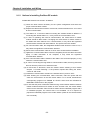
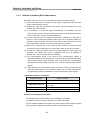
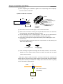
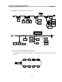
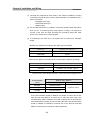
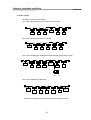
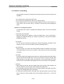
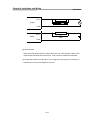
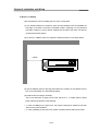
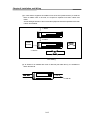
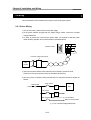
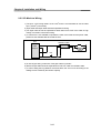
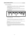
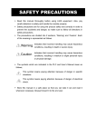
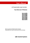
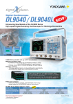
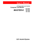
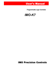
Chapter 9 Installation and Wiring
Chapter 9 Installation and Wiring
9.1 Installation
9.1.1 Installation Environment
This machine has a high reliability regardless of the environment to install. But cares
should be taken to secure the reliability and the safety as follows.
1) Environment Condition
(1) Install it to the control panel available for water-proof and dust-proof.
(2) Do not apply the continuous impact or vibration.
(3) Do not expose it directly to the direct rays.
(4) No dew by the sudden change of temperature.
(5) Do not exceed the surrounding temperature 0~55°C.
(6) Do not exceed the relative humidity 5 ~ 95% .
(7) No corrosive gas or combustible gas.
2) Installation Construction
(1) When working the screw hole and the wiring, it is not allowed to put the wire
remnants into the PLC.
(2) The installation location should be the place to operate.
(3) Do not install it in the same panel with a high voltage machine.
(4) The distance between wiring duct and the surrounding module should be at least
50mm apart.
(5) The grounding should be done on the good place free from the noise.
3) Radiation Design of Control Panel
(1) When installing the PLC in the sealed control panel, the radiation design should
be done considering the radiation of other machine as well as the radiation of
PLC itself. When circulating the air using the vent or the general fan, it may
effect to the PLC system due to the inflow of gas or dust.
(2) It is recommended to install the filter or use the sealed type thermal exchanger.
9-1
Chapter 9 Installation and Wiring
9.1.2
Notices in Installing Profibus-DP module
Profibus-DP Smart I/O can set max. 32 stations.
(1) Check the basic factors necessary for the system configuration and select the
proper communication module.
(2) Prepare the cable and accessories such as tab, terminal resistance etc. to be used
for this communication.
(3) The station no. of all other stations including this module should be different. If
connecting with double station no., it may cause the communication error.
(4) In case of operating with normal communication, the mode switch of master
module should be RUN mode. If changing the mode switch of master module in
the status that other stations are in communication, it may cause the significant
communication obstacle with other stations. So, special cares are needed.
(5) For communication cable, the designated standard cable should be used. If not, it
may cause the significant communication obstacle.
(6) Check if the communication cable is cut off or short-circuited before installation.
(7) Tighten the communication cable connector completely and fix the cable connection
tightly. If cable connection is not complete, it may cause the significant
communication obstacle.
(8) If the communication cable is twisted or the cable is not connected properly, it may
cause the communication error.
(9) In case of connecting the long distance communication cable, the wiring should be
done far from the power line or inductive noise.
(10) If LED action is abnormal, check the trouble causes referring to this manual
Chapter 11.’Trouble Shooting”. If the problem repeats after taking the action,
contact to A/S center.
(11) Install this communication module in the status that PLC power is ‘OFF’.
(12) After finishing the communication cable connection, make the power ON and
check the normal action in the LED action status. If it is normal, download the
corresponding program into GMWIN for GLOFA series and into KGLWIN for
MASTER-K series and run the program.
(13) In case that the power of Remote station among communication stations between
master module and Smart I/O module is ‘OFF’ and then ‘ON’, the remote station
enters into the automatic ‘Start’ if mother station has the initialized program and if
no initialized program, the normal start is not available. So it is required to
prepare the initialized program in the mother station. (Refer to the communication
user’s manual.)
9-2
Chapter 9 Installation and Wiring
9.1.3
Notices in installing DeviceNet module
DeviceNet Smart I/O can set max. 64 stations(included one master module)
(1) Check the basic factors necessary for the system configuration and select the
proper communication module.
(2) Prepare the cable and accessories such as tab, terminal resistance etc. to be
used for this communication.
(3) It is available to control the speed automatically in accordance with the
communication speed of master module by the means of Auto baudrate function
and it is required to comply the cable specification.
(4) In case of using the tab, it is required to use terminal resistance on both side of
the tab. In case of the single network system, set it not to repeat the station no.
Install the master module in the base in the status of PLC power OFF and set
the communication address and communication speed accurately.
(5) Check if the connector pin of this communication module is normal and make
sure that the power cable and the communication cable are not short-circuited.
(6) If using the combined module (GDL-DT4A) when setting the high speed link
parameter, the module will occupy 2 registration lists and it is available to
register max. 31 (but only GDL-DT4A is installed).
(7) The communication speed to be used for this communication module is
125k,250k,500kbps and if changing the communication speed after setting the
communication speed, make the power ‘OFF’ and change the communication
setting switch and then apply the power ‘ON’. Then the changed mode shall be
applied.
(8)
After finishing the communication cable connection, make the power ON and
check the normal action in the LED action status. If it is normal, download the
corresponding program into GMWIN for GLOFA series and run the program.
1) Materials required in installation
Required material
Communication cable
Tab/terminal resistance
24V power supply device
Connection connector
Dnet I/F module
Thick cable/Thin cable
4/8 port tab, terminal resistance:121Ω,
1%, 1/4W
General power supply
Phoenix) 5 pin Female connector
2) Notices in installing the Connector
The following cares should be taken before installing the connector.
(1) Deal the connector when the signal is not loaded in the cable.
(2) If the module installed in the system is in action, stop the action and then install it.
(3) If the power is supplied, the power should be ‘OFF’ before working.
9-3
Chapter 9 Installation and Wiring
(4) After completing the installation, tighten the corresponding cable completely
not to be shaken or removed.
3) How to install the connector
Screw
4cm
Red(V+)
White(CAN_H)
SHIELD
Insulated round cable
Blue(CAN_L)
7cm
5-Pin
connector
(Female)
Black(V-)
(1) Peel off the cover of the cable apprx. 7cm for cable connection.
(2) Remove the covered net covering the signal cable and remove the aluminum
foil covering the signal cable and the power cable.
(3) Cut the shrinkage cover for packing approx. 4cm and rap the cable and then
cover the exposed conductor and insulated coverings of the cable.
(4) Peel off the coverings of the signal cable and the power cable approx. 3mm
from the ends.
(For the safe cabling, apply the heat to the compressed cover for packing and
stick to the cable closely.)
Compressed terminal
Cable(signal cable,
Power cable)
(5) After inserting the peeled coverings into the clamp screw of the connector,
tighten the screw. (Cares should be taken to match the cable with the signal
name of the connector.)
There are 2 ways of cable connection : one way to use the tab as below and
another way to connection by the drop method. DC 24V power should be installed
in the place necessary to maintain the voltage when Smart I/O module is getting
more or the cable is getting longer.
Cable
Tab
Drop cable (max. 6m)
(Thin cable)
Node
9-4
Chapter 9 Installation and Wiring
The method to connect the network is as follows.
Power
Power Supply
Terminal
resistance
Drop line (max. 6m)
Node
Node
Node
Node
Node
Node
Node
Terminal
resistance
Trunk line
Node
Node
Node
Node
4) How to install the tab (Example of 8-Port tab)
It is available to connect to the trunk line of device port tab and connect or remove max. 8
port tab.
J1
J2
J3
J4
J5
J6
J7
J8
9-5
Chapter 9 Installation and Wiring
(1) The drop line composed of Thick cable or Thin cable is available to connect
to the device by the tab and in case of Open-style tab, it is available to use 3
type of connectors.
- Pluggable screw type
- Hard-wired screw type
- Soldered type
(2) For the cable connection, it is ideal to connect the drop line when the system
does not act. If connecting when cable system is acting, it is required to
connect to the trunk line after checking the connection status with other
device not to influence the communication.
(3) If connecting to the trunk line, it is required not to exceed max. allowable
length.
Network max. distance according to the cable type is as follows.
Cable type
Network max. distance
THICK cable
500 m
THIN cable
100 m
Network max. distance according to the communication speed is as follows.
Communication speed
500 kbps
Network max. distance
LTHICK + LTHIN
≤ 100 m
250 kbps
LTHICK + 2.5 ∗ LTHIN ≤ 250 m
125 kbps
LTHICK + 5 * LTHIN ≤ 500 m
LTHICK:THICK cable length (max.8A), LTHIN:THIN cable length(max.3A)
Communication
Network max. distance
speed
THICK cable length
500 kbps
Less than 100 m
250 kbps
Less than 250 m
125 kbps
Less than 500 m
THIN cable length
Less than 100 m
If the communication speed is 500kbps, the length of branch line is less
than 6m and total distance of branch line is less than 39m. And if the
communication sped is 250kbps, the length of branch line is less than 6m
and total distance of branch line is less than 78m and if the communication
speed is 125kbps, the distance of branch line is less than 6m and total
distance of branch line is less than 156m respectively.
9-6
Chapter 9 Installation and Wiring
5) Power Layout
The layout of the power is as follows.
(1) In case of arranging the node on both side of the power,
Communication
power
(2) In case of arranging the node on one side,
Communication
power
(3) In case of installing the double power and dividing the power supply system,
Communication
power
Communication
power
V+
V24V
0V
(4) In case of duplication of the power
Communication
power
Communication
power
The distance between the power and the power tab shall be within 3m.
9-7
Chapter 9 Installation and Wiring
9.1.4 Notices in installing Rnet module
Rnet Smart I/O can set max. 64 stations(included one master module).
1) The station no. of all other stations including this module should be different. If
connecting with double station no., it may cause the communication error.
2) In case of operating with normal communication, the mode switch of master module
should be RUN mode. If changing the mode switch of master module in the status that
other stations are in communication, it may cause the significant communication
obstacle with other stations. So, special cares are needed.
3) For communication cable, the designated standard cable should be used. If not, it may
cause the significant communication obstacle.
4) Check if the communication cable is cut off or short-circuited before installation.
5) Tighten the communication cable connector completely and fix the cable connection
tightly. If cable connection is not complete, it may cause the significant communication
obstacle.
6) If the communication cable is twisted or the cable is not connected properly, it may
cause the communication error.
7) If using the combined module (GRL-DT4A) when setting high speed link parameter, the
module will occupy 2 registration lists and it is available to register max. 31 (but only
GRL-DT4A is installed).
8) In case of connecting the long distance communication cable, the wiring should be done
far from the power line or inductive noise.
9) The (twisted pair) shielded cable of communication cable should be connected with the
body of 9 Pin connector on both side.
10) If LED action is abnormal, check the trouble causes referring to this manual Chapter
11.’Trouble Shooting”. If the problem repeats after taking the action, contact to A/S
center.
11) Install this communication module in the status that PLC power is ‘OFF’.
12) After finishing the communication cable connection, apply the power ON and check the
normal action in the LED action status. If it is normal, download the corresponding
program into GMWIN for GLOFA series and into KGLWIN for MASTER-K series and
run the program.
13) In case that the power of Remote station among communication stations between
master module and Smart I/O module is ‘OFF’ and then ‘ON’, the remote station enters
into the automatic Start if mother station has the initialized program and if no initialized
program, the normal start is not available. So it is required to prepare the initialized
program in the mother station. (Refer to the communication user’s manual.)
9-8
Chapter 9 Installation and Wiring
9.1.5 Notices in installing Modbus module
Modbus Smart I/O can set max. 32 stations.
1) The user must select the action mode for Cnet I/F module correctly and set the action mode
accordingly. If setting the action mode wrong, it may cause the communication error.
2) For the channel using the exclusive communication mode, it is required to set the station no.
In case of the system using the exclusive communication mode and communicating by RS422/485, it is not allowed to have Modbus module of the same station no. in the same
network. In case of RS-422 communication, if there is
double station no., it may cause the
communication error.
3) For communication cable, the designated standard cable should be used. If not, it may
cause the significant communication obstacle.
4) Check if the communication cable is cut off or short-circuited before
installation.
5) Tighten the communication cable connector completely and fix the cable connection
tightly. If cable connection is not complete, it may cause the significant communication
obstacle.
6) RS-422/485 cable should connect the TX/RX correctly. When several stations are
connected, the first 2 stations should be connected by TX and RX and other stations should
be connected by TX to TX and RX to RX themselves. (RS-422 communication)
7) In case of RS-485 communication, TX and RX of Cnet I/F module should be connected
each other.
8) If the communication cable is twisted or the cable is not connected properly, it
may cause the communication error.
9) In case of connecting the long distance communication cable, the wiring should be
separated far from the power line or inductive noise and if necessary, it should be covered.
10) If LED action is abnormal, check the trouble causes referring to this manual Chapter
11.’Trouble Shooting”. If the problem repeats after taking the action, contact to A/S center.
11) In case that the power of Remote station among communication stations between master
module and Smart I/O module is ‘OFF’ and then ‘ON’, the remote station enters into the
automatic Start if mother station has the initialized program and if no initialized program, the
normal start is not available. So it is required to prepare the initialized program in the
mother station. (Refer to the communication user’s manual.).
9-9
Chapter 9 Installation and Wiring
9.1.6 Notices in Handling
Here describes the notices in handling from the opening of each unit and module to the
installation.
• Do not fall it down or apply the strong impact.
• Do not remove the PCB from the case. It may cause the failure.
• Cares should be taken not to make the foreign materials such as the wire remnants etc.
enter inside of the unit when wiring. If it entered, remove them before applying the
power.
1) Notices in handling the product
Here describes the notices in handling and installing the basic unit and the extended
module.
(1) Recheck the I/O standard
Input part should pay the attention to the input voltage and in case of output part, if
applying the voltage exceeding max. capacity to open/close, it may cause the failure,
breakage and the fire.
(2) Use Wire
The wire should be selected considering the ambient temperature, allowable current
2
and the min. spec. of the wire should be more than AWG24(0.18mm ).
(3) Environment
When I/O wiring, if it is close to the heat generating machine or material or if the wiring
is contacted directly to the oil for a long time, it may cause the short-circuit, breakage
and failure.
(4) Polarity
Check the polarity before applying the power to the terminal stand that has the polarity.
Special cares should be taken not to wire AC input power to DC24V external power
supply terminal on the edge of basic unit input part. In case of DeviceNet, 24V power
enters into the communication cable together and it is not necessary to wire separately.
(5) Wiring
• When wiring the I/O line with high voltage cable and the power cable together, the
induction obstacle occurs that may cause the failure and malfunction.
• It is not allowed to pass the cable in front of I/O action indication part (LED). (because it
prevents from distinguishing the I/O indication.)
• In case that the inductive load is connected to the output part, please connect the surge
killer or diode to the load in parallel. Connect the cathode of diode to the ‘+’ side of the
power.
9-10
Chapter 9 Installation and Wiring
OUT
Induction load
Output
Surge killer
COM
Induction load
OUT
+
Output
Diode
COM
(6) Terminal stand
When wiring the terminal stand or making the screw hole, cares should be taken not to
make the wire remnants enter into the PLC. It may cause the malfunction and failure.
(7) Except that mentioned on the above, do not apply the strong impact to the basic or
extended unit or remove the PCB from the case.
9-11
-
Chapter 9 Installation and Wiring
2) Notices in Adding
Here describes the notices in adding the PLC to the control panel.
(1) The sufficient distance is required to have the well-ventilated room and facilitate the
exchange of the basic unit and the extended module. Especially, for the periodical
exchange of battery (3 years), please separate the left side of the basic unit and the
control panel at least 100mm.
(2) For the max. radiation effect, it is required to install it as shown on the figure below.
100mm
(3) Use the different panel for the large sized electronic contactor or the vibration source
such as no-fuse braker etc. and install separately.
(4) Install the duct for wiring if necessary.
But, if the dimension of upper part or lower part of PLC is smaller than the figure
below, please pay attention to the following.
• In case of installing on the upper PLC, the height of wiring duct should be less than
50mm for the good ventilation.
• In case of installing on the lower PLC, please consider minimum radius of the cable.
9-12
Chapter 9 Installation and Wiring
(5) In case that the equipment is installed in front of the PLC (inside the door) to avoid the
effect of radiant noise or the heat, it is required to separate more than 100mm and
install.
And the left/right direction of the unit and the equipment should be separated more than
100mm and installed.
≥ 80mm
≥ 80mm
Other
machine
Radiator
≥ 100mm
PLC Adding
(6) As Smart I/O is installed with Hook for DIN rail (rail width 35mm), it is available to
attach the DIN rail.
DIN rail
9-13
Chapter 9 Installation and Wiring
9.2 Wiring
Here describes the notices related to the wiring in case of using the system..
9.2.1 Power Wiring
1) For the use power, please use DC 24V power supply.
2) If the power variation is larger than the regular range, please connect the constant
voltage transformer.
3) In order to prevent the noise from the power cable, it is required to twist the power
cable densely if possible, and connect within the shortest distance.
DC24 DC24
F
Remote module
Constant voltage transformer
DC
power
4) Connect the power that the noise between lines or between grounds is small.
(if there is much noise, please connect the insulation transformer.)
5) For PLC power, I/O machine and power machine, it is required to divide the system as
follows.
Main power
PLC power
Power
T1
PLC
I/O power
T2
Main circuit machine
I/O machine
Main circuit machine
※ T1,T2: Constant voltage transformer
9-14
Chapter 9 Installation and Wiring
2
6) For the power cable, it is required to use the thick one (2mm ) to make the small falling
down of the voltage.
7) The power DC24V cable is not allowed to approach closely to the main circuit (high
voltage, convection current) cable, I/O signal cable and needs to separate more than
80mm apart.
8) Please use the surge observer to prevent the lightning as shown on the below.
PLC
E1
E2
Surge observer for lightning
Remark
1) Separate the earth(E1) of the surge observer for lightning and the earth (E2) of PLC.
2) Select the surge observe for lightning so that it does not exceed max. allowable voltage
of the observer even when the power voltage is rising maximum.
9) When you are afraid of the invasion of the noise, please use the insulation sealed
transformer or the noise filter.
10) In case of the wiring of each input resource, the wiring of the sealed transformer or
the wiring of the noise filter is not allowed to pass the duct.
9-15
Chapter 9 Installation and Wiring
9.2.2 I/O Machine Wiring
2
1) The spec. of I/O wiring cable is 0.18~2 mm and it is recommended to use the cable
2
spec. (0.5mm ) conveniently.
2) Input cable and output cable should be separated for wiring.
3) I/O signal cable should be separated at least 80mm from main circuit cable of high
voltage, convection current when wiring.
4) In case that it is not available to separate the main circuit cable and the power cable,
please use the shielded cable and earth the PLC.
PLC
Shielded cable
Input
R
Output
DC
5) In case of pipe wiring, make sure of the pipe and then ground it.
6) DC24V output cable should be separated from AC110V cable and AC220V cable.
7) In case of wiring the long distance more than 200m, the error occurs according to the
leakage current caused by the interline capacity.
9-16
Chapter 9 Installation and Wiring
9.2.3 Grounding Wiring
1) As this PLC carries out the sufficient noise policy, it is available to use without
grounding except the case that there is much noise. But, when grounding, please refer
to the following notices.
2) When grounding, please use the exclusive grounding if possible.
rd
For he grounding construction, please use the 3
class grounding (grounding
resistance less than 80 Ω ).
3) If not available to use the exclusive grounding, please use the common grounding as
shown on the figure B).
PLC
Other machine
PLC
(A)
(A) exclusive grounding: Excellent
Other machine
PLC
Other machine
(C)
(B)
(B) common grounding: Good
(C) common grounding : Bad
2
4) Please use the electric wire for grounding more than 2 mm . Place the grounding
point near this PLC if possible and shorten the length of the grounding cable.
When connecting the extended base, please connect the extended connector
accurately.
Do not remove the PCB from the module case and modify the module.
When adding/removing the module, the power should be OFF.
Use the cellular phone or radio phone apart more than 30mm from the product.
I/O signal cable and communication cable should be at least 10cm apart from the high
voltage cable or the power cable to avoid the effect caused by the noise or the change
of magnetic filed.
9-17
Chapter 9 Installation and Wiring
9.2.4 Cable Specification for Wiring
The Cable specification to be used for the wiring is as follows.
2
Cable spec.(mm )
External connection type
Low limit
High limit
Digital input
0.18 (AWG24)
1.5 (AWG16)
Digital output
0.18 (AWG24)
2.0 (AWG14)
Analog I/O
0.18 (AWG24)
1.5 (AWG16)
Communication
0.18 (AWG24)
1.5 (AWG16)
Main power resource
1.5 (AWG16)
2.5 (AWG12)
Protection grounding
1.5 (AWG16)
2.5 (AWG12)
For the power and I/O wiring for Smart I/O, it is required to use the compressed terminal.
• Use ‘M3’ type screw for the terminal.
• Tighten the terminal screw with 6 ~ 9 kg·cm torque.
• Use the fork type screw for the compressed terminal.
Example of the proper compressed terminal
(fork type)
≤ 6.2mm
9-18