1
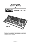
USER’S MANUAL
Before using, we advise you to get familiar with your VECTOR and carefully read the
advices, explanations hereby reported and how to use some special functions
such as the INSERT SPLIT.
All our units are hand made. For this reason you could find design or sound differences.
All this as guarantee that you bought a true hand made product.
1
Congratulations for your choice !
Vector is a professional system able to switch and patch stomp boxes.
It has been designed without compromises in the choice of components and circuit solutions.
Vector circuit uses hi-dynamic power buffer, built around class “A” mosfets.
This design delivers sonic hi performances, especially with vintage equipments
Vector’s buffers are supplied by hi voltage. This solution gives very high dynamic,
ten times more than the normal dynamic requests from your equipments.
The result is a sonically transparent signal path, with very low noise distortion and wide
frequency response.
All the critical switchings are made by opto-coupled switches, to avoid any type of “click”
and “pop”.
All the outputs to external systems are buffered and floating by a transformer. This is to
eliminate any type of “ground loop” and noise.
Vector has a small power amp (1W) useful to play with a headphone or a monitor.
This “monitor” section can be used when there isn’t the possibility to connect the
system to external amps.
Vector has the Emulated line out that allows to play directly into the mixer or for
recording session.
Vector logic is built around a microprocessor, that stores up to 28 presets and related
midi program change, and drives the display and the hardware.
There are 6 loops + 1 fix loop. Into the fix loop you can connect the Vectorexp
that adds 6 loops more to the system. Totally you’ll have 12 loops. This extension
is driven via midi.
Another exclusive feature of Vector is the “Insert Split” that physically splits
the effects in two groups. The first is for synthesis effects like distortions, compressors, eq,
etc; while the second is for the modulation effects like delays, chorus, etc.
Vector puts the first group before the input of the amp, while the second group is in the loop
of the amp. In this way you can use the preamp and the loop of the amp together with
pedals. Absolutely unbelievable!!
Vector has three type of power supply for pedal effects, and it is supplied
with set of cable for this purpose.
9VdC (max 500mA),12VdC (max 500mA) power supply for pedals,9VaC (max 1A) for POD, and
other special effects.
Attention: You may supply only a single appliance.
2
TECHNICAL SPECIFICATIONS
- 5 transparent clickless loop.
- 1 transparent clickless loop serial/parallel with MIX control.
- 1 fix loop for VECTOREXP connection.
- Input transparent buffer ( “A” class mosfet hi-dynamic supply ).
- Buffered tuner out.
- Insert Split loop.
- 4 remote switches.
- A, B out buffered, balanced and floating ( Split transformer ).
- Total true Bypass function.
- System Mute function.
- Absolutely very low noise circuitry.
- On board 1W power amplifier for low level speaker.
- Headphone output jack.
- Emulated, balanced and floating XLR out for direct to mixer or recording.
- Midi out ( 28 program change ).
- 4 banks (0 to 3) and 7 presets (0 to 7).
- “Built in” power supply.
- 9VdC (max 500mA),12VdC (max 500mA) power supply for pedals.
- 9VaC (max 1A) for POD, and other special effects.
Attention: You may supply only a single appliance.
- Dimensions : 625 x 175 x 85 mm
- Weight : 4 kg.
VECTOR’S EQUIPMENT
- Supply cable
- Multiple supply cable for foot pedal
- Instruction manual
- Warranty Card
- Three foam stripes useful on a slippery surface
ELECTRIC CONNECTION
-The electric safety and the correct work is guarantee when the
unit is correctly earthed.
-Ensure that the electric voltage supply is the same as indicated on the back label
3
WHAT HAPPEN WHEN YOU TURN ON THE VECTOR
When you turn on the Vector, using the power switch on the rear panel,
the Vector executes a control procedure as follow :
count down on the display : 39 38 27 26 25 14 13 12 01
lighted sequence of the red lights from right to left.
At the end of this procedure you’ll be in “loop mode” and you’ll see
on the display just two red points.
THREE OPERATION MODES
The “STATUS SW” switch, let you move between three
difference operation modes :
LOOP
Select in real time one of the six loops.
PRESET
Recall one of the preset stored.
STORE
Store the selected loops in a preset .
CONTROLS ON THE FRONT PANEL
MUTE
Mute all the system,(tuner out always active).
SYSTEM BYPASS Take the guitar signal directly from the input to the A or B main out.
STATUS SW
Change mode.
You may select the above three switches anytime.
SWITCHES ON THE “LOOP” MODE
SW1
Remote switch 1 (yellow light)
SW2
Remote switch 2 (yellow light)
LOOP 1
Select loop 1
LOOP 2
Select loop 2
LOOP 3
Select loop 3
LOOP 4
Select loop 4
LOOP 5
Select loop 5
LOOP 6
Select loop 6
OUT B
Select the “A” main out, when the green light is off.
Select the “B” main out, when the green light is on.
4
SWITCHES ON THE “PRESET” MODE
BANK UP switch
Let you move up on the four banks ( from 0 to 3).
BANK DOWN switch
Let you move down on the four banks ( from 3 to 0).
Switch 1
Recall preset 01 ; 11 ; 21 ; 31
Switch 2
Recall preset 02 ; 12 ; 22 ; 32
Switch 3
Recall preset 03 ; 13 ; 23 ; 33
Switch 4
Recall preset 04 ; 14 ; 24 ; 34
Switch 5
Recall preset 05 ; 15 ; 25 ; 35
Switch 6
Recall preset 06 ; 16 ; 26 ; 36
Switch 7
Recall preset 07 ; 17 ; 27 ; 37
Each switch may recall 4 presets.
CONTROLS ON THE REAR PANEL
INPUT
Guitar jack input
TUNER
Tuner out, (always active).
INSERT SPLIT
amp IN
amp SEND
amp RET
Using an amplifier in to the Insert Split (see example)
you may split synthesis effects before the input amplifier
and modulation effects in the amplifier’s loop.
The Vector automatically adjusts levels and impedances.
MAIN OUT A
A System output
MAIN OUT B
B System output
VOLUME
Adjusts the volume on outs :
HEAD PHONE, SPEAKER and Emulated line out
HEAD PHONE
Head phone output
SPEAKER
Output for a monitor ( 16 Ω / 1 W).
REM SW1
Remote switch 1
to control the channel switching of a head.
REM SW2
Remote switch 2
to control the channel switching of a head.
MIDI OUT
Send a program change corresponding to the recalled preset,
on the midi channel 1.
5
EMULATED
LINE OUT
Emulated output (balanced and floating )You can go directly into a
recording system or into a mixer.
LOOP 1
SEND
RETURN
SW
Send loop 1
Return loop 1
Remote switch (active when you select the loop1).
LOOP 2
SEND
RETURN
SW
Send loop 2
Return loop 2
Remote switch (active when you select the loop2).
LOOP 3
SEND
RETURN
Send loop 3
Return loop 3
LOOP 4
SEND
RETURN
Send loop 4
Return loop 4
We suggest that you use these four loops for synthesis effects only.
(i.e. compressor, booster, wha etc. ).
LOOP FIX
SEND
RETURN
Send loop FIX
Return loop FIX
The LOOP FIX is an Insert point that can be used in some different ways :
- connect the optional unit VectorExp to have other 6 loops controlled by the Vector (Midi).
- a loop effect always active.
- a volume pedal that sets to zero “0” the volume without cut delay and/or reverb.
LOOP 5
SEND
RETURN
Send loop 5
Return loop 5
LOOP 6
SEND
RETURN
MIX %
Send loop 6
Send loop 6
Effect mix control, between the effect and the original sound.
We suggest that you use these two loops for modulation effects only.
(i.e. chorus, flanger and delay ).
9VdC
Supply for 9VdC units ( max current 0,5 A).
12VdC
Supply for 12VdC units ( max current 0,5 A).
9VaC
Supply for 9VaC unit ( max current 1 A).
6
INSERT SPLIT FUNCTION
The INSERT SPLIT is a function of the Vector, unique in its kind,
that lets you manage your foot pedals set-up, in a correct and efficient way.
Connecting an amplifier to the INSERT SPLIT ( see example 2 in the following pages)
the Vector puts:
-
Loop 1-2-3-4 before the input amplifier
-
Loop 5 - 6 in the amplifier’s loop,
with the automatic adjust of levels and impedances.
We suggest that you use loops 1-2-3-4 for synthesis foot pedal effects as :
compressor, wha, distortion and booster,
while Loops 5-6 for modulation foot pedal effects as : chorus, flanger and delay.
On the Vector the INSERT SPLIT area is indicated as follow:
amp IN
amp SEND
amp RET
to the input of the amplifier
to the Send of the amplifier
to the Return of the amplifier
The connection chain will be as shown in the following diagram.
WARNING
Using an amplifier with the Insert Split connection the B system output doesn’t work.
7
HOW TO RECALL A LOOP IN REAL TIME ( LOOP MODE)
When you are in Loop Mode,
you can select in real time the following functions :
-
remote switch SW1 and SW2
one or more loops of the six available
A or B output system
MUTE function
SYSTEM BYPASS function
HOW TO STORE A PRESET
You can decide which loops or controls select in a preset.
To store a preset follow the below instructions:
-
Turn on the Vector ( Loop Mode).
-
Select loops from 1 to 6 ( indicated by green lights on the panel).
-
Select SW1 and/or SW2 (indicated by yellow lights on the panel),
i.e. to control the channel switching of a head.
-
Select the A or B system by switch no. 7.
When the green light is turned off it means that you selected the A system,
when it is turned on, you selected the B system.
-
Push and hold the “STATUS SW” switch for few seconds, the display will blink.
-
Use BANK UP and BANK DOWN to select one of the four banks (from 0 to 3).
-
Push and hold the preset number switch (from 1 to 7) to assign the preset number into the
selected bank. The display will stop blinking. This operation confirm you the good result
of the store.
N.B.
Every time that you recall a stored preset the Vector shows you which loop
has been selected. ( green and yellow lights).
8
HOW TO RECALL A PRESET
When you have stored a preset (see paragraph before) the Vector passes automatically to the
PRESET mode. Use BANK UP and BANK DOWN to recall the bank number.
Use switches from 1 to 7 to recall the stored preset number.
Note 1
In our electric test, during the production cycle, on the preset 01 we stored
the function : SW1, SW2, Loop 1, 2, 3, 4, 5, 6 and B system output.
Anyway you can change settings on the preset 01.
All the other presets are empty.
Note 2
When you are in LOOP mode you can pass in PRESET mode pressing STATUS SW one time.
Note 3
When you are in PRESET mode if you need to go back in STORE mode, before you have to
pass through the LOOP mode, pressing STATUS SW switch once , after pressing and holding
for the second time this switch for few seconds the display blinks (STORE mode).
HOW TO SET AN EFFECT IN SEND / RETURN MODE ON LOOP 6
Connecting an effect into the LOOP 6, using the control knob ”MIX%”, you can obtain a wide mix
level between the original sound and the effect.
Setting on 0% you have only the original sound while on 100% the sound will be completely
processed by the effect( Serial Mode).
Setting from 0 to 100% you will have a progressive mix between the original sound and
the effect (Parallel Mode).
When you select the Parallel Mode you have to set on zero “0” the Direct ( or Dry) level
on your effect to obtain o good sound.
9
CLEANING
Before any kind of cleaning operation, disconnect the appliance from the electric supply.
-
Do not throw water jets directly on the appliance.
Do not use water steams to clean the appliance.
Do not use solvents to clean the appliance.
Surface
Cleaning system suggested
Satin Aluminium
Soft cloth + product for metal parts
Stainless steel
Paper + product for chrome parts
Warning
• The manufacturer declines all responsibility for any kind of damage to persons, things
and/or animals resulting from a wrong use of the appliance.
• The appliance ‘s conformity is proved by CE symbol on the rear side.
• The manufacturer reserves the right to make any useful and essential changes to its
products without compromise the main safety and working features.
• Do not use the appliance barefoot.
• Do not touch the appliance with wet or moist hands or feet.
• Do not allow children or incompetents to use the appliance.
• Do not leave inflammable materials near to the appliance.
• Do not pull up the appliance by control knobs.
• Read carefully, compile and deliver the warranty attached to the appliance.
• The appliance’ s repair may be done during the warranty period only by us, in our laboratory,
or by authorized staff, in conformity to the national previsions in force.
• Control periodically all cables supplied with the appliance, if they result damaged, you have to
replace them immediately with another one with the same characteristics.
• In case of damage contact the shop where you bought the appliance.
• The appliance must be earthed in conformity to the national previsions in force.
For any further information and/or support contact us.
Brunetti Marco & C. S.a.s
Via De’ Bonomini, 25/27
I – 41100 MODENA –ITALIA
Phone number : +39 059 / 243404
Fax number :
+39 059 / 216464
http://www.brunetti.it
e-mail : [email protected]
e-mail : [email protected]
commercial info
technical info
10
Balanced Out
VECTOR FLOW DIAGRAM
Volume
Control
Amp.
1W
EMU
Cuffia
System
Bypass
Mute
Monitor
x1
Loop
2
Loop
3
Loop
4
Loop
Fix
Insert
Split
x1
Buffer
Loop
5
Buffer
Mix
Tuner
Return
Loop
1
Send
INPUT
VECTOR
Loop
6
Mute
Out A
Mute
Out B
Balanced Out
INSERT SPLIT FLOW DIAGRAM
With the INSERT SPLIT connection
the BYPASS function doesn't work
Mute
Loop
4
Loop
Fix
amp
In
x1
Buffer
Buffer
-20dB
Tuner
Loop
5
Mix
Out A
amp RET
Loop
6
INSERT SPLIT
AREA
Speaker
Amplifier
(Head or Combo)
Input
Amp.
Pre
Amp.
Send
Amp.
Return
Amp.
Cuffia
Monitor
+20dB
Loop
3
Return
Loop
2
amp
Send
Send
Loop
1
x1
Amp.
1W
EMU
Mute
INPUT
VECTOR
Volume
control
Power
Amp.
X
amp SEND
Attenuation
-20dB
amp RET
Gain
+20dB
BANK and PRESET
BANK UP and BANK DOWN switches let you move up and down in the four banks
(from 0 to 3) when you are in PRESET mode.
The bank number appears on the display (left side).
The switches from 1 to 7 let you recall one of the seven presets on each bank.
The preset number appears on the display (right side).
25
EXAMPLE A
REAL TIME FUNCTIONS SELECTION IN LOOP MODE
Press the "a" switch to active the remote switch SW2
Press the "b" switch to select the loop 2
Press the "c" switch to select the loop 3
Press the "d" switch to select the loop 5
Press the "e" switch to active B outlet (green led lighted)
a
b
c
d
e
EXAMPLE B
STORE A PRESET
a
In LOOP mode select the functions you want to store in the preset.
(i.e. remote switch 1, loop 1-4-6 and B output).
b
Press and hold the switch STATUS SW for about 3 seconds (the display will blink)
in this way you are in store mode.
c
Use BANK UP and BANK DOWN to select the bank number from 0 to 3 (i.e. bank 2).
d
Select the preset number from 1 to 7 (i.e. preset 5). Press and hold the switch 5 for about 3 seconds,
the display will stop blinking as a confirm that the preset has been stored.
b
25
a
c
a
a
d
a
a
EXAMPLE C HOW TO RECALL A PRESET
After the store operation the Vector passes directly in PRESET mode.
If the Vector is in LOOP mode you have to press STATUS SW switch once to pass in PRESET mode.
Before recalling a preset you have to select the bank number using the BANK UP and BANK DOWN.
Each time you recall a preset, the lighted leds show you the loops and the functions stored.
If we consider the example B the functions lighted will be the following:
In these areas you can
write your presets.
Press the STATUS SW switch
if you desire to go back
in loop mode.
25
EXAMPLE D USING VECTOR AS MIDI FOOT CONTROLLER
Recalling a preset in PRESET mode, Vector generates thru the MIDI OUT, on the midi channel 1,
the Program Change with the same number shown by the display.
All the 28 Program Change can be used to control other midi units.
Program change number generated
25
FUNCTIONS DESCRIPTIONS
Where not specified
all the jack cables are mono
Outputs controlled
by this volume :
- HEAD PHONE
- SPEAKER
- Emulated line out
Headphone
Monitor
(16ohm minimum)
Mixer
Program change for :
- Midi channel switching
- Midi effects
Guitar
Midi cable
(to Midi In)
INSERT SPILT
connection area
Balanced cable
Cannon-Cannon
Cannon-Jack
Remote
switches
+
Footpedals control area
12v/0,3A
-
EXAMPLE 1
Where not specified
all the jack cables are mono
HEAD
COMBO
CHANNEL
SWITCH
CHANNEL
SWITCH
IN
IN
Guitar
CABINET
+
12v/0,3A
-
Power cable
9V dC
IN
OUT
OUT
IN
VOLUME
PEDAL
OUT
PEDAL 4
PEDAL 5
OUT
IN
PEDAL 3
IN
PEDAL 2
OUT
PEDAL 1
Direct
IN
0%
Effect
100%
OUT
PEDAL 6
IN
EXAMPLE 2
INSERT SPLIT CONNECTION
Where not specified
all the jack cables are mono
Mixer
IN
Send
CHANNEL
SWITCH
Return
Guitar
IN
To theP.A. or
RECORDING
SYSTEM
HEAD
Loop
OUT
VOLUME
PEDAL
PEDAL 4
Balanced cable
Cannon-Cannon
Cannon-Jack
CABINET
Suono Diretto
Emulato
The B Main Out
doesn't working
+
12v/0,3A
-
Using the INSERT SPLIT
function you'll have:
Power cable
9V dC
Loop 1-2-3-4 after the guitar
OUT
IN
OUT
PEDAL 5
OUT
IN
PEDAL 3
IN
PEDAL 2
OUT
PEDAL 1
Direct
IN
0%
Effect
100%
OUT
PEDAL 6
IN
Loop 5-6 in the amp's loop
(send/return).
EXAMPLE 3
EFX
IN
The preset number on the EFX's display
is the same generated by the Vector on
its MIDI OUT outlet.
This number appears on the Vector's display too.
THRU
IN
COMBO
IN
Guitar
MIDI
OUT
SND RET MIDI IN
Headphone
Tuner
Midi cable
+
12v/0,3A
-
Where not specified
all the jack cables are mono
Power cable
9V dC
IN
OUT
PEDAL 1
OUT
IN
OUT
PEDAL 5
OUT
IN
PEDAL 3
WHA WHA
PEDAL
PEDAL 2
Direct
IN
0%
Effect
100%
OUT
PEDAL 6
IN
EXAMPLE 4
SETUP LIVE
Where not specified
all the jack cables are mono
To the P.A. or
RECORDING
SYSTEM
Guitar
CHANNEL
SWITCH
HEAD
Mixer
IN
Microphoned sound
Tuner
IN
OUT
Balanced cable
Cannon-Cannon
Cannon-Jack
WHA WHA
PEDAL
Balanced cable
Cannon-Cannon
Cannon-Jack
CABINET
+
12v/0,3A
-
Il mix% regola la
miscelazione tra il suono
originale e il suono effettato.
Cavo alim.
9V dC
IN
OUT
OUT
IN
VOLUME
PEDAL
OUT
PEDALE 4
PEDALE 5
IN
PEDALE 3
OUT
PEDALE 2
OUT
PEDALE 1
Direct
IN
Emulated
direct sound
IN
0%
OUT
Effect
100%
IN
PEDALE 6
In questo caso se Ë
possibile eliminare la diretta
dall'effetto a pedale.
EXAMPLE 5
Where not specified
all the jack cables are mono
HEAD
COMBO
CHANNEL
SWITCH
CHANNEL
SWITCH
IN
IN
Guitar
CABINET
+
12v/0,3A
-
IN
OUT
IN
OUT
IN
PEDAL 6
OUT
PEDAL 5
IN
You can connect two or
more footpedals effect
into the same loop.
PEDAL 4
OUT
PEDAL 3
IN
PEDAL 2
OUT
PEDAL 1
Power cable
9V dC
IN