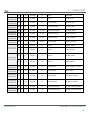
1
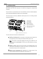
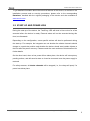
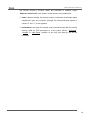
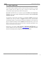
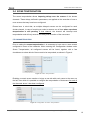
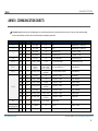
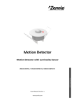
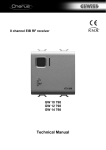
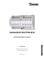
MAXinBOX SHUTTER 8CH 8-Channel Shutter Actuator Application program version: [1.0] User manual edition: [1.0]_a www.zennio.com USER MANUAL ZIO-MBSHU8 MAXinBOX SHUTTER 8CH CONTENTS Contents ........................................................................................................................................ 2 1 Introduction .......................................................................................................................... 3 1.1 MAXinBOX SHUTTER 8CH ................................................................................................. 3 1.2 Installation........................................................................................................................ 4 1.3 Start-Up and Power Loss .................................................................................................. 5 2 Configuration......................................................................................................................... 6 2.1 General ............................................................................................................................. 6 ETS Parameterisation .................................................................................................... 6 2.2 Outputs............................................................................................................................. 7 2.2.1 Manual Control ........................................................................................................ 7 ETS Parameterisation .................................................................................................... 9 2.3 Logic Functions ............................................................................................................... 11 2.4 Scene Temporisation...................................................................................................... 12 ETS Parameterisation .................................................................................................. 12 ANNEX I. Communication Objects............................................................................................... 14 http://www.zennio.com Technical Support: http://zennioenglish.zendesk.com 2 MAXinBOX SHUTTER 8CH 1 INTRODUCTION 1.1 MAXINBOX SHUTTER 8CH MAXinBOX SHUTTER 8CH from Zennio is a KNX specific actuator for controlling motorised shutter / blind systems. The most outstanding features are: 16 relay outputs, configurable as up to 8 independent shutter channels (with or without slats). 20 customisable, multi-operation logic functions. Scene-triggered action control, with an optional delay in the execution. Manual operation / supervision of the 8 shutter channels through the onboard pushbuttons and LEDs. http://www.zennio.com Technical Support: http://zennioenglish.zendesk.com 3 MAXinBOX SHUTTER 8CH 1.2 INSTALLATION MAXinBOX SHUTTER 8CH connects to the KNX bus through the on-board KNX connector. Once the device is provided with power from the KNX bus, both the individual address and the associated application program may be downloaded. This device does not need any additional external power since it is entirely powered through the KNX bus. 1 7 5 1. Upper Outputs. 2. Lower Outputs. 3. Prog./Test LED. 4. KNX Bus Connector. 5. Prog./Test Pushbutton. 6. Manual Control Pushbutton. 7. Output Status LED. 6 3 2 4 Figure 1. MAXinBOX SHUTTER 8CH The main elements of the device are described next. Test/Prog. Pushbutton (5): a short press on this button sets the device into the programming mode, making the associated LED (3) light in red. Note: if this button is held while plugging the device into the KNX bus, the device will enter into safe mode. In such case, the LED will blink in red every 0.5 seconds. Outputs (1 and 2): output ports for the insertion of the stripped cables of the systems being controlled by the actuator (see section 2.2). Please secure the connection by means of the on-board screws. Manual control pushbuttons (6): pushbuttons for a direct control of the shutter channels during the set-up process. See section 2.2.1. http://www.zennio.com Technical Support: http://zennioenglish.zendesk.com 4 MAXinBOX SHUTTER 8CH To get detailed information about the technical features of this device, as well as on the installation process and on security procedures, please refer to the corresponding Datasheet, bundled with the original packaging of the device and also available at www.zennio.com. 1.3 START-UP AND POWER LOSS During the start-up of the device, the Test/Prog. LED will blink in blue colour for a few seconds before the device is ready. External orders will not be executed during this time, but afterwards. Depending on the configuration, some specific actions will also be performed during the start-up. For example, the integrator can set whether the shutter channels should change to a particular position and whether the device should send certain objects to the bus after the power recovery. Please consult the next sections of this document for further details. On the other hand, when a bus power failure takes place, the device will interrupt any pending actions, and will save its state so it can be recovered once the power supply is restored. For safety reasons, all shutter channels will be stopped (i.e., the relays will open) if a power loss takes place. http://www.zennio.com Technical Support: http://zennioenglish.zendesk.com 5 MAXinBOX SHUTTER 8CH 2 CONFIGURATION 2.1 GENERAL After importing the corresponding database in ETS and adding the device into the topology of the desired project, the configuration process begins by right-clicking into the device and selecting Edit parameters. ETS PARAMETERISATION The only parameterisable screen available by default is General. From this screen it is possible to activate/deactivate all the required functionality. Figure 2. General screen Once activated, Outputs, Logic Functions and Manual Control bring additional tabs to the menu on the left. These functions and their parameters will be explained in later sections of this document. The Manual Control function is enabled by default, and so is the corresponding configuration tab. Sending of Indication Objects (0 and 1) on Bus Voltage Recovery: this parameter lets the integrator activate two new communication objects (“Reset 0” and “Reset 1”), which will be sent to the KNX bus with values “0” and “1” respectively whenever the device begins operation (for example, after a bus power failure). It is possible to parameterise a certain delay to this sending (0 to 255 seconds). http://www.zennio.com Technical Support: http://zennioenglish.zendesk.com 6 MAXinBOX SHUTTER 8CH 2.2 OUTPUTS MAXinBOX SHUTTER 8CH incorporates 16 relay outputs, configurable as up to 8 independent shutter channels, each of which will operate one motorised shutter system. For detailed information about the functionality and the configuration of the parameters related to the shutter channels, please refer to the specific manual “Shutter channels in MAXinBOX Shutter 8CH”, available at the Zennio homepage (www.zennio.com). 2.2.1 MANUAL CONTROL MAXinBOX SHUTTER 8CH allows commanding the shutter to move up or down through the pushbuttons on the top of the device. Two specific pushbuttons are provided per channel (i.e., one per relay output). Manual operation can be done in two different ways, named as Test On Mode (for testing purposes during the configuration of the device) and Test Off Mode (for a normal use, anytime). Whether both, only one, or none of these modes are available needs to be parameterised in ETS. Moreover, it is possible to enable a specific binary object for locking and unlocking the manual control in runtime. Note: The Test Off mode will be active (unless it has been disabled by parameter) after a download or a reset with no need of a specific activation – the pushbuttons will respond to user presses from the start. On the contrary, switching to the Test On mode (unless disabled by parameter) needs to be done by long-pressing the Prog/Test button (for at least three seconds), until the LED is no longer red and turns yellow. From that moment, once the button is released, the LED light will remain green to confirm that the device has switched from the Test Off mode to the Test On mode. After that, an additional press will turn the LED yellow and then off, once the button is released. This way, the device leaves the Test On mode. Note that it will also leave this mode if a bus power failure takes place. http://www.zennio.com Technical Support: http://zennioenglish.zendesk.com 7 MAXinBOX SHUTTER 8CH Test Off Mode Under the Test Off Mode, the shutter channels can be controlled through both their communication objects and the actual pushbuttons located on the top of the device. When one of these buttons is pressed, the shutter will behave as if an order had been received through the corresponding communication object, and will also send the status objects when required. This behaviour depends on the length of the button press: A long press makes the shutter start moving (upwards or downwards, depending on the button being pressed). The LED will light in green until the end of the motion. If the button gets pressed being the shutter already at the top or bottom positions, nothing will happen (the LED will not light). A short press will make the shutter drive stop (if in motion), as it normally does when a step/stop order is received from the KNX bus. In case of not being the shutter in motion, pressing the button does not cause any action, unless slats/lamellas have been parameterised – in such case, a step movement (up/down, depending on the button pressed) will take place. Regarding the lock, timer, alarm and scene functions, the device will behave under the Test Off mode as usual. Button presses during this mode are entirely analogous to the reception of the corresponding orders from the KNX bus. Test On Mode After entering the Test On mode, it will only be possible to control the shutters through the on-board pushbuttons. Orders received through communication objects will be ignored. Pressing the button will make the shutter drive move upward or downward (depending on the button) until the button is released again, thus ignoring the position of the shutter and the parameterised times. The LED will light in green while the button is being hold. For safety reasons, the device does not allow the activation of the two outputs of a shutter channel at the same time. If the button of one of the outputs is held while the other output is active, the device will first deactivate it and afterwards perform the required action on the output associated to the button pressed. http://www.zennio.com Technical Support: http://zennioenglish.zendesk.com 8 MAXinBOX SHUTTER 8CH Note: due to the actions that may have been performed during the Test On mode, the device will ignore the real status of the shutter when the user leaves such mode. Therefore, the Test On mode is useful to synchronise the device status and the actual status of the shutter.. The lock, timer, alarm and scene functions as well as any orders received from the KNX bus will not have an effect over the shutter status while the device is under the Test On mode. The shutter status objects will not be sent to the bus, either. On the contrary, the alarm and lock objects will be re-evaluated after leaving the Test On mode, so any changes that may have taken place in Test On will be considered when leaving. Important: the device is factory delivered with both manual modes (Test Off and Test On) enabled by default. ETS PARAMETERISATION The manual control is configured from the Configuration tab, under Manual Control. The only two parameters are: Figure 3. Manual Control Manual Control: options are “Disabled”, “Only Test Mode Off”, “Only Test Mode On” and “Both Test Mode Off and On” (default). Depending on the selection, the device will permit using the manual control under the Test Off, the Test On, or both modes. Note that, as stated before, using the Test Off mode does not require any special action, while switching to the Test On mode does require long-pressing the Prog/Test button. Manual Control Lock: unless the above parameter has been “Disabled”, the Lock Manual Control parameter provides an optional procedure for locking http://www.zennio.com Technical Support: http://zennioenglish.zendesk.com 9 MAXinBOX SHUTTER 8CH the manual control in runtime. When this checkbox is enabled, object “Manual Control Lock” turns visible, as well as two more parameters: Value: defines whether the manual control lock/unlock should take place respectively upon the reception (through the aforementioned object) of values “0” and “1”, or the opposite. Initialization: sets how the manual control should remain after the device start-up (after an ETS download or a bus power failure): “Unlocked”, “Locked” or “Last Value” (default; on the very first start-up, this will be unlocked). http://www.zennio.com Technical Support: http://zennioenglish.zendesk.com 10 MAXinBOX SHUTTER 8CH 2.3 LOGIC FUNCTIONS This module makes it possible to perform numeric and binary operations to incoming values received from the KNX bus, and to send the results through other communication objects specifically enabled for this purpose. MAXinBOX SHUTTER 8CH can implement up to 20 different and independent functions, each of them entirely customisable and consisting in up to 4 consecutive operations each one. The execution of each function can depend on a configurable condition, which will be evaluated every time the function is triggered through specific, parameterisable communication objects. The result after executing the operations of the function can also be evaluated according to certain conditions and afterwards sent (or not) to the KNX bus, which can be done every time the function is executed, periodically or only when the result differs from the last one. Please refer to the specific “Logic Functions in MAXinBOX SHUTTER 8CH” user manual (available at the Zennio homepage, www.zennio.com) for detailed information about the functionality and the configuration of the related parameters. http://www.zennio.com Technical Support: http://zennioenglish.zendesk.com 11 MAXinBOX SHUTTER 8CH 2.4 SCENE TEMPORISATION The scene temporisation allows imposing delays over the scenes of the shutter channels. These delays, defined in parameters, are applied on the execution of one or more scenes that may have been configured. Please bear in mind that, as multiple delayed scenes can be configured for each shutter channel, in case of receiving an order to execute one of them when a previous temporisation is still pending in that channel, the channel will interrupt such temporisation and will only execute the delay and the action of the new scene. ETS PARAMETERISATION Prior to setting the scene temporisation, it is necessary to have one or more scenes configured in some of the channels. When entering the Configuration window under Scene Temporization, all configured scenes will be listed, together with a few checkboxes to select which of them need to be temporised, as shown in Figure 4. Figure 4. Scene Temporization Enabling a certain scene number n brings a new tab with such name to the menu on the left, from which it is possible to configure the temporisation of that scene for each of the channels where it has been configured. Figure 5. Configuration of Scene Temporization http://www.zennio.com Technical Support: http://zennioenglish.zendesk.com 12 MAXinBOX SHUTTER 8CH Therefore, parameter “Scene m. Channel z Delay” defines the delay that will be applied to the action defined in channel z for the execution of scene m. The range of this delay is 0 to 3600 seconds, 0 to 1440 minutes or 0 to 24 hours. http://www.zennio.com Technical Support: http://zennioenglish.zendesk.com 13 MAXinBOX SHUTTER 8CH ANNEX I. COMMUNICATION OBJECTS “Functional range” shows the values that, with independence of any other values permitted by the bus according to the object size, may be of any use or have a particular meaning because of the specifications or restrictions from both the KNX standard or the application program itself. Number Size 1 1 Bit 2 1 Bit I/O Flags Data Type (DPT) Functional Range Name Function CT--- DPT_Trigger 0/1 Reset 0 Voltage Recovery -> Sending of 0 CT--- DPT_Trigger 0/1 Reset 1 Voltage Recovery -> Sending of 1 1 Bit I C--W- DPT_Switch 0/1 Lock Manual Control 0 = Lock; 1 = Unlock 1 Bit I C--W- DPT_Switch 0/1 Lock Manual Control 0 = Unlock; 1 = Lock 4 - 35 1 Bit I C--W- DPT_Bool 0/1 [FL] (1 bit) Data Entry x Binary Data Entry (0/1) 36 - 51 1 Byte I C--W- DPT_Value_1_Ucount 0 - 255 [FL] (1 byte) Data Entry x 1 byte Data Entry (0-255) 0 - 65535 -32768 – 32767 -273.00 – 670760.00 -2147483648 2147483647 [FL] (2 bytes) Data Entry x 2 bytes Data Entry [FL] (4 bytes) Dato de entrada x 4 bytes Data Entry 3 52 - 67 2 Bytes I C--W- DPST-7-1 DPST-8-1 DPST-9-1 68 - 75 4 Bytes I C--W- DPT_Value_4_Count 76 - 95 1 Bit O CTR-- DPT_Bool 0/1 [FL] Function x – Result (1 bit) Boolean 1 Byte O CTR-- DPT_Value_1_Ucount 0 - 255 [FL] Function x – Result (1 byte) Unsigned 2 Bytes O CTR-- DPT_Value_2_Ucount 0 - 65535 [FL] Function x – Result (2 bytes) Unsigned [FL] Function x – Result (4 bytes) Signed 4 Bytes O CTR-- DPT_Value_4_Count -2147483648 2147483647 1 Byte O CTR-- DPT_Scaling 0% - 100% [FL] Function x – Result (1 byte) Percentage 2 Bytes O CTR-- DPT_Value_2_Count -32768 - 32767 [FL] Function x – Result (2 bytes) Signed [FL] Function x – Result (2 bytes) Float [Shutter] Scenes 0 - 63 (Execute 1 - 64); 128 - 191 (Save 1 - 64) 2 Bytes O CTR-- DPT_Value_Temp -671088.00 – 670760.00 96 1 Byte I C--W- DPT_SceneControl 0-63; 128-191 97, 114, 131, 148, 165, 182, 199, 216 1 Bit I C--W- DPT_UpDown 0/1 [Cx] Move 0=Raise; 1=Lower 98, 115, 132, 149, 1 Bit I C--W- DPT_Step 0/1 [Cx] Stop/Step 0=Stop/StepUp; 1=Stop/StepDown http://www.zennio.com Technical Support: http://zennioenglish.zendesk.com 14 MAXinBOX SHUTTER 8CH 166, 183, 200, 217 1 Bit I C--W- DPT_Trigger 0/1 [Cx] Stop 0=Stop; 1=Stop 1 Bit I C--W- DPT_Enable 0/1 [Cx] Lock 0=Unlock; 1=Lock 1 Bit O CTR-- DPT_Switch 0/1 [Cx] Rise Relay (Status) 0=Opened; 1=Closed 1 Bit O CTR-- DPT_Switch 0/1 [Cx] Lower Relay (Status) 0=Opened; 1=Closed 1 Byte O CTR-- DPT_Scaling 0% - 100% [Cx] Shutter Position (Status) 0%=Top; 100%=Bottom 1 Byte O CTR-- DPT_Scaling 0% - 100% [Cx] Slats Position (Status) 0%=Open; 100%=Closed 1 Byte I C--W- DPT_Scaling 0% - 100% [Cx] Shutter Positioning 0%=Top; 100%=Bottom 1 Byte I C--W- DPT_Scaling 0% - 100% [Cx] Slats Positioning 0%=Open; 100%=Closed 1 Bit I C--W- DPT_Alarm 0/1 [Cx] Alarm 0=No Alarm; 1=Alarm 1 Bit I C--W- DPT_Alarm 0/1 [Cx] Alarm 0=Alarm; 1=No Alarm 1 Bit I C--W- DPT_Alarm 0/1 [Cx] Alarm 2 0=No Alarm; 1=Alarm 1 Bit I C--W- DPT_Alarm 0/1 [Cx] Alarm 2 0=Alarm; 1=No Alarm 1 Bit I C--W- DPT_Trigger 0/1 [Cx] Unfreeze Alarm Alarm=0 + Unfreeze=1 => End Alarm 1 Bit I C--W- DPT_UpDown 0/1 [Cx] Move (Reversed) 0=Lower; 1=Raise 110, 127, 144, 161, 178, 195, 212, 229 1 Bit I C--W- DPT_Trigger 0/1 [Cx] Direct Positioning 0=No Action; 1=Go to Position 111, 128, 145, 162, 179, 196, 213, 230 1 Bit I C--W- DPT_Trigger 0/1 [Cx] Direct Positioning 2 0=No Action; 1=Go to Position 1 Bit I C--W- DPT_Trigger 0/1 [Cx] Direct Positioning (Save) 0=No Action; 1=Save Current Position 1 Bit I C--W- DPT_Trigger 0/1 [Cx] Direct Positioning 2 (Save) 0=No Action; 1=Save Current Position 99, 116, 133, 150, 167, 184, 201, 218 100, 117, 134, 151, 168, 185, 202, 219 101, 118, 135, 152, 169, 186, 203, 220 102, 119, 136, 153, 170, 187, 204, 221 103, 120, 137, 154, 171, 188, 205, 222 104, 121, 138, 155, 172, 189, 206, 223 105, 122, 139, 156, 173, 190, 207, 224 106, 123, 140, 157, 174, 191, 208, 225 107, 124, 141, 158, 175, 192, 209, 226 108, 125, 142, 159, 176, 193, 210, 227 109, 126, 143, 160, 177, 194, 211, 228 112, 129, 146, 163, 180, 197, 214, 231 113, 130, 147, 164, 181, 198, 215, 232 http://www.zennio.com Technical Support: http://zennioenglish.zendesk.com 15 Join and send us your inquiries about Zennio devices: http://zennioenglish.zendesk.com Zennio Avance y Tecnología S.L. C/ Río Jarama, 132. Nave P-8.11 45007 Toledo (Spain). Tel. +34 925 232 002. Fax. +34 925 337 310. www.zennio.com [email protected]