1
TOPP PRO
NF03495
-RS
TPM9.1000 TOPP PRO_V1.1
TPM9.1000
0.13KG/1
NH00149 3:1 NH00231 1:2
A3
A4
A5
feedback
1.1
SEIKAKU TECHNICAL GROUP LIMITED
26
NPD-TO-1105004
NO
1
13PCS
AUG.03.2011
2011.08.03
TPM 9.1000
NF03495-1.1
4
7
16
19
20
21
22
24
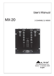
Thank you for your purchasing of TOPP PRO TPM9.1000. The TPM9.1000 is designed to be a portable solution
that includes a mix, an amplifier. It builds with 2*500W power amplifier and available with 14-channel
configurations, 24-bit multi-effects processor with 100 presets, built-in compressor/ limiter, 7-band EQ and
RCA I/O with dedicated volume control. They are designed to be rugged, powerful and filled with quality features
that would usually be found in much large systems.
Please read this manual carefully so you can take advantages of all the features of TPM9.1000.
Thanks again for choosing TOPP PRO.
*9MIC/LINE input channels, 7/8,9/10 & 11/12 channels are stereo channels, the remaining are
mono channels
*Each input channel with volume, left & right, DSP volume, high/mid/low volume controls and +20dB PAD
*+15V phantom power for condenser MIC
*2-way RCA channel input R/L stereo signal in 13/14 channel by TAPE IN
*2-way RCA channel output R/L stereo signal for external effect or other device
*Mp3 works in 11/12 or 13/14 channel controlled by MP3IN switch
*STEREO, MONITOR, and BRIDGE outputs
*Built-in DSP effect with 100 presets
*7-band stereo graphic equalizer(63, 160, 400, 1K, 2.5K, 6.3K, 16KHz)
*500W*2(4ohm load) maximum power for amplifier
*Toroidal transformer, bridge rectifier, filter and 78, 79 series voltage regulator
*Mains power can switch between 115V/230V
This is the fastest way to get something out from your TPM9.1000, if you have a keyboard and a microphone
a. Plug the microphone into Channel 1MIC IN.
b. Turn down AUX and LEVEL controls on the input channel.
c. Put the EQ controls on center position.
d. Connect 2 passive cabinets to the rear speaker cabinets.
e. Turn on your TPM9.1000
f. Sing or speak into the microphone with normal volume and adjust the channel LEVEL control of half.
g. If you like, you can adjust the EQ at this stage.
h. The LED on the Master LED meter should flash only occasionally, otherwise you will hear distortion. If this LED
is not active and you still hear distortion, please turn down a little the input LEVEL control or reduce the output
level of your source instrument.
i. Connect your stereo keyboard into channel 7/8 and repear the sequence.
Here you are. It is your first gig with your TPM9.1000.
MONO/STEREO Input Channel Section
Your TPM9.1000 comprises 6 mono input channels and
2 stereo input channels, each of them including -20dB
PAD, 3-band equalizer, AUX sends, PAN and LEVEL controls.
The following content will detail the each part.
1- MONO Input Channels(1~6)
Ch1 through Ch6 are provided of MIC IN and LINE IN connector.
Use the XLR MIC IN connector to connect low noise microphones
preamp and low level signal, which also feature +15V phantom
power, allowing you to connect condenser microphones. Use
the 1/4" TRS LINE IN connector to connect either a microphone
or a line level instrument such as synthesizer, drum machine, effects
processors...
Note: when +15V phantom power is already on, you shall
never connect an unbalanced microphone to the XLR connector
if you do not want to damage both the microphone and the mixer.
2- STEREO Input Channels(7~12)
Ch7 through Ch12 are organized in stereo pair. Via the 1/4'TRS input
connectors, you can connect the outputs from stereo devices such as
synthesizers, effects processor or any stereo line level signal. If only
the left jack was connected, the input will operate in mono mode. Via
the XLR MIC IN connector, you can connect the low level sources.
3- 20dB PAD Button
Pressing this button will attenuate the input signal by 20dB. In such way
you can produce increased headroom and reduce the risk of distortion due
to quite "hot" signals.
4- SG/PEAK LED
Inside your TPM9.1000, the audio signal is monitored in several different
stages and then sent to this LED. When the LED is red illuminated, it warns
that you are reaching signal saturation and possible distortion, then you
should reduce the input level for avoiding distortion.
5- EQUALIZER
Your TPM9.1000 features a 3-band equalizer allowing you to adjust the high,
mid and low frequencies separately on each channel. High and low frequencies
provides a boost or cur up to 15dB, 12dB for mid frequency, flat at the center
detent.
HIGH
This is the treble control. You can use it to get rid of high frequency noises or to boost the sound of cymbals or
the high harmonics of the human voice.
MID
This is the midrange control. It affects most fundamental frequencies of all musical instruments and human voice.
An attentive use of this control will give you very wide panorama of sound effects.
LOW
This is the bass control. It is used to boost male voice, kick drum and bass guitar. Your system will sound much
bigger than what it is.
6- MON Control
Your TPM9.1000 has two auxiliary sends which can be used for sending signals to external or internal effects
device or for creating a monitor mix, these sends are used to adjust the level of respective channel signal sent to
AUX bus, and the adjustable range goes from - to +10dB. The control is configured as PRE-FADER, which means
that the signal is sent out before reaching the channel fader. It is used for a stage monitor mix in a live set, or for
a headphone mix in recording application.
7- DSP/FX Control
The control is configured as POST-FADER, so the AUX send level will be affected by channel fader. Via the AUX 1
OUT jack, the AUX 1signal can be sent to an external effects device, furthermore, the AUX1 signal can also be
assigned to internal onboard effect module.
8- PAN Control
Abbreviation of PANORAMA control for mono and stereo channels. It is used to determine the amount of channel
signal sent to main mix left and right outputs. Keeping this control in center position, the signal will be positioned
in middle of "stereo field". Turn this control fully counterclockwise, the signal will be present only on the left of
main mix and vice-versa.
9- Channel LEVEL Control
This control is used to adjust the overall level of respective channel. The adjustable range goes from -
10- LAMP Jack & Switch
This lovable LAMP is very convenient for your operation, it is
located in the top right corner of the front panel, and provides
the 12V socket that can drive standard BNC-type lamp.(PIN1 is
connected to negative terminal, PIN2 is connected to positive
terminal). By pressing this switch, you can turn on the lamp.
11- +15V Phantom Power & LED
It is available only to the XLR MIC sockets. Never plug in a
microphone when phantom power is already on. The LED
illuminates when the switch is ON. Before turning phantom
power on, make sure that all faders are all the way down. In
this way you will protect your stage monitor and main loudspeakers
to +10dB.
20
21
22
23
24
25
26
27
28
29
30
31
32
33
34
35
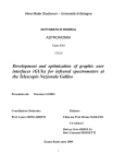
USB Player Section (Optional)
This section can be selected and installed according to user's requirement. Please see the installation
procedure .(USB Module Installation)
Option One - Song Module
The file system of USB memory for USB players is FAT16 and FAT32, and these players can only decode
MP3. It has 7 rank subordinate folders at most.
(6)
(4)(2) (1) (3)(5)
1- USB port: For connecting with USB memory equipment.
2PRE: In pause state, press this key, it will go to the
USB PLAYER
previous song and still keep in pause state; In play state,
press this key, it will go to the previous song and start
playing; Furthermore, press this key and hold for a few
TAC-MP3-S
seconds to decrease the volume.
3NEXT: In pause state, press this key it will go to the next song and still keep in pause state; In play state,
press this key it will go to the next song and start playing; Furthermore press this key and hold for a few
seconds to increase the volume.
4PLAY/PAUSE:In play state, press this key to pause the player; In pause state, press it to start playing.
5- STOP: In play state, press this key to stop playing and all the songs in USB memory will appear on the
display ; In stop state, press STOP/
PRE/
NEXT keys again to go to first song and the player will
keep in pause state, then press
PLAY/PAUSE key to play the song.
6- DISPLAY: All the USB player information are monitored through this sexy and magic display.
Operation Instruction for Song Module
1- When no USB key inserted, the display will show as Fig. 1.
2- Inserted the USB key, the USB player starts to search the songs in USB key,
INSERT USB KEY
Fig 1
and the display shows "Searching". At the end of the search, the display
will show as Fig. 2.Using
PRE/
NEXT keys, you can select one of
following three menu options ("Playing", "Program" and "Folder List").
Press Playing, the unit will enter into the corresponding operation mode.
MENU:
PLAYING
PROGRAM
FOLDER LIST
3- "Playing" mode - single song play
Fig 2
a). In Fig 2, selecting the Playing mode to recall following interface. This
display shows the name of all the folders containing MP 3 files. Using the
PRE/
classic music
PLAY/PAUSE
jazz music
STOP to return to Fig 2
pop music
NEXT keys, you can scan the folders, then press
key, you will open corresponding folders. Press
FOLDER:
interface.
Fig 3
b). After opening the folder, the display will show as Fig 3. This display shows MP 3 file list, and
scrolling list using
PRE/
NEXT keys you can choose the desired song. Press the
PLAY/PAUSE
key, the selected song playback will start. In order to stop playback, you
just need to press the
stop key. Then, if you press the
PLAY/PAUSE
[ 002 ] 00 : 05
key, the song playback will start from the pause point, if you press again
01. Plena pop 01.mp
the
02. Pop 02.mp3
stop key, the system will return to Fig 3 interface.
03. Plena pop 03.mp
Fig 4
4- "Program" mode
a) In Fig 2, select "Program" to enter into the following interface:
"Play list Set": Set the playing list.
"Playing List": Play list.
Press
PRE /
NEXT key to select, press
PLAYLIST SET
STOP key to return the Fig 2
PLAYING LIST
interface.
Fig 5
b) After entering into the "Play List Set", the display will show as Fig 3.
Selecting the desired folder, the display will show the following interface.
The display will show all the MP 3 files, the selected song will be inserted
into the playing list and a mark will appear. Press again you're going to
delete the song from the playing list, and the mark will disappear. Press the
STOP key, you will return to Fig 2 interface. The playing list can accept up to
classic music
[ . ] p3
Plena pop
[ ]Plena pop 02.mp
[ . ]Plena pop 03.mp
Fig 6
20 songs, and it will display the list according to song insert order.
c) The display will show the following interface. Press the
key, you can select the starting song, then press the
selected song playback will start. Press
STOP key, the playback will stop. Press
PRE /
NEXT
PLAY/PAUSE key, the
PLAY/PAUSE key again, or press
PLAY/PAUSE key again, or press
CN22
CN11
CN3
CN22
CN11
CN3
CN22
CN11
[ . ] 00 : 20
01. lena pop 02.mp3
02. Plena pop 06.mp
03. Plena pop 04.mp
STOP key, the playback will start again from the same point. Twice press
Fig 7
STOP, the USB player will return to Fig 3 interface.
5-Folder List:
See the Fig 3, the display shows MP 3 files folders names. Use
CN3
PRE/
NEXT key to scan, press
PLAY/PAUSE key, you'll enter into corresponding folder. In order to return to Fig 5 interface, you just
need to press the
STOP key.
Option Two - Track Module
The file system of USB memory for USB players is FAT16 and FAT32, and these players can only decode MP3. It has 7
rank subordinate folders at most.
1- USB PORT
For connecting with USB memory.
2-
PRE
In pause state, press this key, it will go to previous track
and keep in pause state. In play state, press this key, it will
go to the previous track and start playing.
(8)
(2) (1) (3) (4)
USB PLAYER
TAC-MP3-T
3NEXT
In pause state, press this key, it will go to next track and keep in pause state.
In play state, press this key, it will go to the next track and start playing.
POWER
(Push & Hold)
(5)(6)
4- RPT
Press this key, the player will change between the following four modes:
REP ALL means to repeat all tracks in the memory, mark on the screen is
REP1 means to repeat one track, the mark on the screen is
Play in order means to play the tracks according to the order, the mark on the screen is blank.
Random play means to play the tracks at random, the mark on the screen is A.
(7)
5-
PLAY/PAUSE
In play state, press
PLAY/PAUSE key to pause the player. In pause state,press
PLAY/PAUSE key to start playing.
6- STOP
In play state, press this key to stop playing and all the songs in USB memory will appear on the display ; In stop state,
press STOP/
PRE/
NEXT keys again to go to first song and the player will keep in pause state, then press
PLAY/
PAUSE key to play the song.
7- POWER(Push & Hold)
When the unit is off, press this key and hold for about 2 or 3 seconds to turn on the power supply of the player.
Repeat the above operation, you can turn off the power supply of the player.
8- DISPLAY:
All MP3 player information are monitored via this sexy & magic display.
NOTE: basic interface instruction
When the player isn't connected to a USB memory equipment, the interface is as follows:
When the player is searching for USB tracks, the interface is as follows:
When the player is in pause state, the interface is as follows:
When the player is in use, the interface is as follows:
Option Three - Recording Module
The file system of USB memory for USB players is FAT16 and FAT32, and these players can only
decode MP3. It has 7 rank subordinate folders at most.
1- USB PORT
(9)
(2) (1) (3)(4)
For connecting with USB memory.
CN3
CN22
CN11
2PRE
In pause state, press this key, it will go to previous track and keep
in pause state. In play state, press this key, it will go to the previous
track and start playing.
USB PLAYER-RECORDER
VOL+ VOL-
TAC-MP3-R
REC
RPT POWER
(Push & Hold)
(5)(6)(7)
3NEXT
In pause state, press this key, it will go to next track and keep in pause state. In play state, press this key,
it will go to the next track and start playing.
4- VOL-/VOL+
Press VOL-/VOL+ key to increase or decrease volume during Power on state. The default factory setting is 10.
(8)
5-REC
In power on state, press this key, it will go to the recording preparation state. Press REC again to start recording.
Any other operations are not available in recording state until press POWER to stop recording; if th e word Err
appears during recording, press POWER to stop.
6PLAY/PAUSE
In play state, press
PLAY/PAUSE key to pause the player. In pause state, press
PLAY/PAUSE key to start playing.
7- RPT
Press this key, the player will change between the following four modes:
REP ALL means to repeat all tracks in the memory, mark on the screen is
REP1 means to repeat one track, the mark on the screen is
Play in order means to play the tracks according to the order, the mark on the screen is blank. Random play means
to play the tracks at random, the mark on the screen is A.
8-POWER(Push & Hold)
When the unit is off, press this key and hold for about 2 or 3 seconds to turn on the power supply of the player.
Repeat the above operation, you can turn off the power supply of the player.
9- DISPLAY
All the USB player information are monitored through this sexy & magic display.
USB Module Installation
-No selective mode
At normal state, there is no selective mode on the front panel, only a piece of panel without function.
CN3
CN22
CN11
-USB PLAYER selective mode
Please connect the 5PIN row-wire on the USB module to the CN22 header and 2 PIN row-wire to CN 11header on
front panel. For Recording module, you also need to connect the 3 PIN row-wire to CN 3 header to start recording
function. Then fix the USB module on the front panel with two screws.
USB PLAYER
TAC-MP3-S
CN3
CN22
CN11
CN3
CN22
CN11
CN3
CN22
CN11
A)Song Module
USB PLAYER
TAC-MP3-T
POWER
(Push & Hold)
B)Track Module
USB PLAYER-RECORDER
VOL+ VOL-
TAC-MP3-R
REC
RPT POWER
(Push & Hold)
C)Recording Module
REAR PANEL
TPM 9.1000
AC INPUT
LEFT/MAIN
OUTPUT 1
1+
POS
CAUTION
1NEG
RISK OF ELECTRIC SHOCK
DO NOT OPEN
MODEL
RATED POWER CONSUMPTION: 1300W
OUTPUT 2
220 - 240V
CAUTION:
SERIAL
RIGHT/MONO
REPLACE WITH THE SAME TYPE FUSE AND RATING
DISCONNECT SUPPLY CORD BEFORE CHANGING FUSE
OUTPUT 2
1+
POS
110 - 127V
WARNING: SHOCK HAZARD - DO NOTOPEN
AVIS: RISQUE DE CHOC ELECTRIQUE - NE PAS OUVRIR
OUTPUT 1
FUSE
110 -127V ~ 60Hz T- 12A 250V
220 - 240V ~ 50Hz T- 6.3A 250V
1NEG
BRIDGE MODE
STEREO MODE:
BRIDGE
1+
2+
POS NEG
2x500 W @ 4 OHM
2x300 W @ 8 OHM
BRIDGE MODE:
1000 W @ 8 OHM
(4 OHM MIN. LOAD)
(8 OHM MIN. LOAD)
CLASS 2 WIRING MAY BE USED
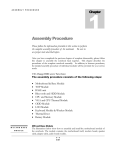
44- AC INPUT with FUSE Holder
Use it to connect your TPM9.1000 to the main AC with the supplied AC cord. Please check the voltage available
in your country and how the voltage for your unit is configured before attempting to connect your unit to the
main AC.
45- VOLTAGE Selector
There are two kinds of voltages for your operation. From this switch you can select the voltage at 100~127VAC
or 220~240VAC.
46- SPEAKERS Jacks
These jacks are used to connect speakers. They are configured with 4-way speakon connectors and 1/4" phone
jacks. You can determine the signal that is output to these jacks according to the setting of the AMPLIFIER MODE
select switch.
Note: in order to avoid damage to the built-in amplifier, please pay attention to the allowed impedance of the
speaker. Very low load impedances may damage the amplifier.
OK, You have got to this point and you are now in the position to successfully operate your TPM9.1000
however, we advice you to read the following section carefully to be the real master of your own mix.
Not paying enough attention to the input signal level, the routing of the signal and the assignment of
the signal will result in unwanted distortion, a corrupted signal or no sound at all. So you should follow
this procedure for every single channel:
1- Turn down all input and output gain controls.
2- Connect phantom powered microphones before switching on the +15V phantom power switch.
3- Set the output level of your TPM9.1000 or the connected power amplifier at no more than 75%.
4- Position EQ controls on middle position.
5- Position panoramic (PAN) control on center position.
6- Increase the input gain properly for maintaining the good headroom and ideal dynamic range.
7- Depending on the actual application, turn slowly the input and output level controls for obtaining
the maximum gain before distortion.
8- NOw repeat the same sequence for all input channels. The main LED meter could move up into the
red section. In this case you can adjust the overall output level through the main mix control.
Audio Connections
You can connect unbalanced equipment to balanced inputs and outputs. Simply follow these schematics.
30
31
32
34
35
MAIN SPEAKERS CONNECTION
Please use only the power connectors to make connections with other signal source equipment
for the passive speaker cabinets. The power connector has four terminals:1+, 1-, 2+, 2-.
19
20
21
22
23
24
25
26
27
27
28
29
With the AMPLIFIER MODE switch in BRIDGE position, the two power amplifiers in your TPM9.1000
drive together a single speaker cabinet with the sum of the power of the 2 amps. Usually this solution
is used to drive a single subwoofer and the main out output on the front panel are used to feed a pair
of powered speakers as mid-high units.
TPM 9.1000
AC INPUT
LEFT/MAIN
OUTPUT 1
1+
POS
CAUTION
1NEG
RISK OF ELECTRIC SHOCK
DO NOT OPEN
MODEL
OUTPUT 2
220 - 240V
CAUTION:
SERIAL
RIGHT/MONO
REPLACE WITH THE SAME TYPE FUSE AND RATING
DISCONNECT SUPPLY CORD BEFORE CHANGING FUSE
OUTPUT 2
1+
POS
110 - 127V
WARNING: SHOCK HAZARD - DO NOTOPEN
AVIS: RISQUE DE CHOC ELECTRIQUE - NE PAS OUVRIR
OUTPUT 1
FUSE
110 -127V ~ 60Hz T- 12A 250V
220 - 240V ~ 50Hz T- 6.3A 250V
RATED POWER CONSUMPTION: 1300W
1NEG
BRIDGE MODE
STEREO MODE:
BRIDGE
1+
2+
POS NEG
2x500 W @ 4 OHM
2x300 W @ 8 OHM
BRIDGE MODE:
1000 W @ 8 OHM
(4 OHM MIN. LOAD)
(8 OHM MIN. LOAD)
CLASS 2 WIRING MAY BE USED
TPM 9.1000
USB PLAYER
TAC-MP3-T
POWER
(Push & Hold)
9
9
3