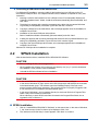
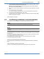
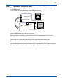
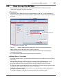
1
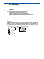
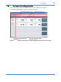
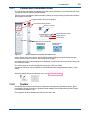
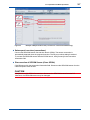
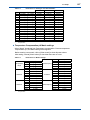
User’s Manual Model SPS24 SENCOM PC Software IM 12A01S02-01E IM 12A01S02-01E 1st Edition i uPreface Thank you for purchasing the SPS24 SENCOM PC Software. Please read the following respective documents before installing and using the SPS24 SENCOM PC Software. The SPS24 SENCOM PC Software is designed to connect and manage SENCOM sensors for tasks including calibration. For information about the SENCOM sensor, WU11 SENCOM cable, and FLXA21 2-wire analyzer, please refer to their respective manuals. l Target readers of this document This document has been compiled for readers who have the basic software and hardware knowledge required to install the SPS24 SENCOM PC Software as well as to operate Microsoft Windows operation systems. l Version up The SPS24 SENCOM PC Software can download a version up product from the following site. http://www.yokogawa.com/an/soft/sps24/ Media No. IM 12A01S02-01E 1st Edition : May 2013 (YK) All Rights Reserved Copyright © 2013, Yokogawa Electric Corporation IM 12A01S02-01E 1st Edition : May 10, 2013-00 ii u Safety Precautions n Safety, Protection, and Modification of the Product • In order to protect the system controlled by the product and the product itself and ensure safe operation, observe the safety precautions described in this user’s manual. We assume no liability for safety if users fail to observe these instructions when operating the product. • Modification of the product is strictly prohibited. n Notes on Software • YOKOGAWA makes no warranties, either expressed or implied, with respect to the software’s merchantability or suitability for any particular purpose, except as specified in the terms of warranty. • This product may be used on a machine only. If you need to use the product on another machine, you must purchase another product. • It is strictly prohibited to reproduce the product except for the purpose of backup. • Store the CD (the original medium) in a safe place. • It is strictly prohibited to perform any reverse-engineering operation, such as reverse compilation or reverse assembling on the product. • No part of the product may be transferred, converted or sublet for use by any third party, without prior written consent from YOKOGAWA. n Notes on Handling User’s Manuals • Please read the information thoroughly before using the product. • The purpose of these user’s manuals is not to warrant that the product is well suited to any particular purpose but rather to describe the functional details of the product. • No part of the user’s manuals may be transferred or reproduced without prior written consent from YOKOGAWA. • YOKOGAWA reserves the right to make improvements in the user’s manuals and product at any time, without notice or obligation. • If you have any questions, or you find mistakes or omissions in the user’s manuals, please contact our sales representative or your local distributor. l Signal Words The following words are used in this manual. CAUTION This symbol gives information essential for understanding the operations and functions. NOTE This symbol indicates information that complements the present topic. l Drawing Conventions Some drawings may be partially emphasized, simplified, or omitted, for the convenience of description. Some screen images depicted in the user’s manual may have different display positions or character types (e.g., the upper / lower case). Also note that some of the images contained in this user’s manual are display examples. IM 12A01S02-01E 1st Edition : May 10, 2013-00 iii n Copyright and Trademark Notices The copyrights of online manual contained in the CD are reserved. The online manual is protected by the PDF security from modification, however, it can be output via a printer. Printing out the online manual is only allowed for the purpose of using the product. When using the printed information of the online manual, check if the version is the most recent one by referring to the CD’s version. No part of the online manual may be transferred, sold, distributed (including delivery via a commercial PC network or the like), or registered or recorded on video tapes. • Microsoft, Windows, Windows 7 and Windows XP are either registered trademarks or trademarks of Microsoft Corporation in the United States and/or other countries. • All other company and product names mentioned in this user’s manual are trademarks or registered trademarks of their respective companies. • We do not use TM or ® mark to indicate those trademarks or registered trademarks in this user’s manual. n End User License Agreement ATTENTION! Please read this End User License Agreement (hereinafter referred to as the “Agreement”) carefully before installing the Software product. This End User License Agreement is a legal AGREEMENT between you (either as a registered individual developer or as the registered developer/representative and on behalf of a single entity) and Yokogawa Electric Corporation (hereinafter referred to as “Yokogawa”) for the Yokogawa software product identified following. This Agreement defines the terms and conditions to use this software product. If you choose “I accept the terms of the license agreement.” in order to continue to install this software product, the action indicates your acceptance of the terms and conditions of this Agreement. If you do not agree to the terms and conditions of this Agreement, Yokogawa asks you to choose “I do not accept the terms of the license agreement.” It means that you can not install and use this software product. If you don’t accept the terms and conditions of this Agreement, kindly return this software product to the seller within thirty (30) days from your receipt of this software product without delay. If you don’t return it within such thirty (30) days, you shall be considered that you accept the terms and conditions of this Agreement. 1. Grant of License Subject to the terms and conditions of this Agreement, Yokogawa grants you the right to use one copy of the following software product (hereinafter referred to as the “Software Product”) on a single computer. Product: SENCOM PC Software (SPS24) and materials related thereto that Yokogawa designates Number of License: 1 (one) License 2. Term of License (1) Yokogawa grants you non-transferable and non-exclusive license to use the Software Product, which Yokogawa owns under copyright, industrial property right or any other intellectual property right or Yokogawa is granted to license by third parties. (2) You are licensed to install the Software Product on the computer and use it within the number of the license. (3) Unless otherwise agreed to in writing by Yokogawa, you are not entitled to partition, amend, translate or modify, copy, sell, distribute, transfer, lend or grant sub-license to the third parties, or transmit from one computer to the other computer the Software Product. (4) You are not entitled to make copies of the Software Product regardless of forms, unless you make only one copy for the purpose of necessary back-up or preservation. You shall preserve and take charge of such copy with strict care. (5) The Software Product, any and all proprietary technology, algorithm, and know-how such as process contained in Software Product shall be the proprietary property of Yokogawa or third parties, which grant Yokogawa the rights. You shall keep them strictly confidential and in a specified place, and by no means shall you disclose or publish to any third party except to your limited employees or the equivalents thereto. You are also required to impose the same confidentiality obligation on them. (6) Reverse engineering, attempting to reverse engineer, or change to man-readable form by decompile or disassemble are prohibited. 3. Limitation for Specific Uses (1) Except in the case that you and Yokogawa agreed in writing separately, the Software Product is not designed and/or made specially for the purpose of service of aircraft or ships or support on the ground, or planning, design, construction, maintenance, operation or use of facilities of nuclear and atomic energy. (2) When you use the Software Product for the purposes described in the preceding article 3. (1), Yokogawa shall not bear any and all liability and responsibility for claims and losses arising out of or in relation to such uses. 4. Warranty (1) Yokogawa warrants that the Software Product shall properly function as set forth in the Instruction Manual thereof etc., which Yokogawa publishes, on the hardware and operating system which Yokogawa recognizes the proper function and under the environmental or other conditions designated by the vendor of such hardware and operating system or by Yokogawa. However, in no event shall Yokogawa warrants the following under any operating environment and circumstance. The Software Product; a) will never be interrupted b) will never be free from defect c) be completely corrected d) will be free from any cross interference such as cross conflict with other software e) will satisfy any particular of you or your customer and/or prospective purpose f) will be accurate, correct, reliable or most up-dated (2) The warranty period of the Software Product (hereinafter referred to as the “Warranty Period”) shall be one (1) year after receipt. IM 12A01S02-01E 1st Edition : May 10, 2013-00 iv (3) During the Warranty Period defined above, if the Software Product fails to operate in accordance with the steps of the Instruction Manual etc. attributable to Yokogawa, or defects such as damage of media of the Software Product attributable to Yokogawa are found and you notify Yokogawa of such purport in writing within the Warranty Period, Yokogawa agrees to either repair it or replace the media free of charge, providing the use under the proper operating environment and circumstance which Yokogawa designates. Such repair or replacement shall be executed by sending of the media from Yokogawa to you. At your request and upon availability, other works except for such sending of the media (including but not limited to installation, setting-up) shall be executed with charge separately. 5. Exception of Warranty Yokogawa’s warranty set forth in Article 4. above shall not apply if the defect of the Software Product is caused by any of the following: a) where the Software Product was used or operated under the operating environment and circumstance, which does not comply with the terms that Yokogawa or vendors of hardware and operation system designated by Yokogawa; b) where you or a party you designate (including your customer) misused, renovated, up-graded, or used the Software Product for any other purpose than set forth in the Instruction Manual etc.; c) where you or your customer does not execute the proper trouble or non-conformity avoiding measures (including repair or replacement) Yokogawa proposed; d) where any third party other than entrusted by Yokogawa conducted renovation, or improvement of the Software Product; or e) other cause of defect not attributable to Yokogawa 6. If You are not the End User If you are not the end user of the Software Product, you shall present the terms and conditions of this Agreement to your end user and have your end user observe such terms and conditions. If Yokogawa incurs damage due to the breach of such terms and conditions by your end user, you shall indemnify and hold Yokogawa harmless. In this case, the license of the Software Product is the end user, and if you are not the end user, you shall transfer the possession of media and related materials of the Software Product to your end user. 7. Patent or Copyright Infringement If and when any third party should demand injunction, initiate a law suit, or demand damages against you under patent right (including utility model right, design patent, and trade mark) copyright any other rights relating to any of the Software Product including related materials, you shall notify Yokogawa to that effect in writing without delay. In such case, you shall assign to Yokogawa all of the rights to defend you and to negotiate with the claiming party. Further you shall provide Yokogawa with necessary information or any other assistance for Yokogawa’s defense and negotiation. If and when such a claim should be attributable to Yokogawa, Yokogawa shall defend you and negotiate with the claiming party at Yokogawa’s cost and expense and be responsible for the final settlement or judgment granted to such claiming party. 8. Limitation of Liability Yokogawa shall not be responsible for any indirect damage (including but not limited to loss of operational profit, loss of interruption of your business, and loss of business information) and that Yokogawa’s liability to your damage shall not exceed the price amount of the Software Product, which Yokogawa received, even if Yokogawa has been advised of the possibility of such damage. Please note that Yokogawa shall be released and discharged from part or all of the liability hereunder, if you modify, remodel, combine with other software etc., or cause any deviation from the original specifications, without Yokogawa’s prior written consent. 9. Export You shall not (re-)export or transmit, regardless of direct or indirect, the Software Product, its related documents and technical information, and results, which is created through the use of the Software Product without observation of the export control laws and regulations of Japan and other related countries and acquisition of necessary (re-)export or import license at your responsibility. 10. Commencement of Validity This Agreement shall become effective from the day which you install the Software Puroduct, or thirty (30) days after the day which you receive the Software Product, whichever comes first. 11. Termination by without Cause You or Yokogawa may terminate this Agreement with thirty (30) days written notice to the other party. 12. Termination by Cause Yokogawa may terminate this Agreement without any notice or demand to you immediately, if you breach any of the terms and conditions of the Agreement. 13. Effect of Termination (1) Article 2. (5), 7., 8. and 14. shall survive any termination of this Agreement. (2) When this Agreement is terminated, you shall return the Software Product and its copies to Yokogawa without delay, and if you destroy and dispose of the medium of the Software Product under Yokogawa’s consent, you shall delete the contents of such media or destroy media surely. (3) When this Agreement is terminated, Yokogawa shall not obligate to refund the price amount Yokogawa received to you. 14. Governing Law (1) This Agreement shall be governed by and construed under the laws of Japan. (2) All disputes, controversies or differences which may arise between the parties hereto, out of or in relation to or in connection with this Agreement shall be finally settled by arbitration in Tokyo, Japan in accordance with the Commercial Arbitration Rules of The Japan Commercial Arbitration Association. The award rendered by the arbitrator(s) shall be final and binding upon the parties hereto. Concluded. IM 12A01S02-01E 1st Edition : May 10, 2013-00 Toc-1 Model SPS24 SENCOM PC Software IM 12A01S02-01E 1st Edition CONTENTS uPreface.............................................................................................................i u Safety Precautions........................................................................................ii 1.Introduction................................................................................................ 1-1 1.1Outline................................................................................................................. 1-1 1.2 Screen Configuration........................................................................................ 1-2 1.2.1 Connection Information Field.............................................................. 1-3 1.2.2Toolbar................................................................................................ 1-3 2. 3. 1.2.3 Menu Bar............................................................................................. 1-4 1.2.4 Function Information Field.................................................................. 1-4 Preparation and Basic Operation............................................................ 2-1 2.1 Driver Installation............................................................................................... 2-1 2.2 SPS24 Installation.............................................................................................. 2-3 2.3 Confirming Installation and Uninstallation..................................................... 2-4 2.4 Sensor Connection............................................................................................ 2-5 2.5 How to use the SPS24....................................................................................... 2-6 Sensor Management................................................................................. 3-1 3.1[Performance]..................................................................................................... 3-1 3.2 [Sensor setup].................................................................................................... 3-2 3.3 [Start calibration]............................................................................................... 3-3 4. Database Viewer........................................................................................ 4-1 5. Error Information....................................................................................... 5-1 6.Setup........................................................................................................... 6-1 6.1 RS Port Number................................................................................................. 6-2 6.2 Communication Log.......................................................................................... 6-2 6.3 Unit Setting......................................................................................................... 6-2 6.4Display................................................................................................................. 6-2 6.5 Select Language................................................................................................ 6-2 6.6 User Account...................................................................................................... 6-2 6.7pH/ORP................................................................................................................ 6-4 7.Account...................................................................................................... 7-1 Revision Record........................................................................................................i IM 12A01S02-01E 1st Edition : May 10, 2013-00 1-1 <1. Introduction> 1.Introduction This section outlines the SENCOM PC Software and explains general items users must understand before using this software. 1.1Outline The SPS24 SENCOM PC Software has the following features. • Handling SENCOM sensors at a laboratory and so on • Calibrating and measuring up to four sensors simultaneously • Managing sensor related data such as calibration and setting sensor data • Managing up to 100 SENCOM sensors simultaneously • Setting each password according to its control level SENCOM sensors can perform measurement in combination with the FLXA21 2-wire analyzer. Sensors are usually calibrated with the analyzer at the site. However, the SPS24 enables operators to calibrate sensors at a laboratory or other places as long as the SPS24-installed PC is provided. SENCOM sensors are connected by using connectors, so they can be easily connected to or detached from the cable. After calibration, the SPS24 helps sensors store the calibration data in their own memory. When such a sensor is connected to the FLXA21, calibration data in the sensor is automatically sent to the FLXA21. WU11 SENCOM cable USB cable Windows PC (user prepared) SPS24 SENCOM PC Software Interface box (up to 4 units) SENCOM sensor (up to 4 units) Figure 1.1 Connection example of SENCOM sensors IM 12A01S02-01E 1st Edition : May 10, 2013-00 1.2 1-2 <1. Introduction> Screen Configuration When launching the SPS24, the Current measurement readings screen appears. Content differs depending on settings or sensor connections. Menu bar (Section 1.2.3) Connection information field (Section 1.2.1) Figure 1.2 Toolbar (Section 1.2.2) Function information field (Section 1.2.4) Example of start screen (the number after the item refers to the relevant section) IM 12A01S02-01E 1st Edition : May 10, 2013-00 1.2.1 1-3 <1. Introduction> Connection Information Field The connection information field displays the status and information of connected sensors, and can also be used for switching target sensors. Sensors can be connected or disconnected by clicking on the [Connect] or [Disconnect] buttons at the bottom of the field. Toggle between wide/narrow display Connected sensor button Sensor number Model (SensorType) ID(Serial No.) Comments Sensor not connected Target sensor for calibration Figure 1.3 Target sensor for display Screen example of connection information field When “Sensor Not Connected” is shown despite a sensor being connected, disconnect the sensor from the cable, reconnect, and click [Connect] again. Information about the connected sensor is displayed on the sensor connection button along with the connection status. The sensor type can be set using [Sensor setup] (pH, ORP, pH+ORP). An optional comment can be entered for sensor identification using [Database viewer] – [Edit data]. When the display shows the following icons, see “5. Error Information”. 1.2.2Toolbar The toolbar has function switch buttons for [Sensor management], [Database viewer], [Error information], [Setup], and others. Clicking a button displays the corresponding function screen. For details, see sections 3 to 7. This operation is also available from [View] on the menu bar. IM 12A01S02-01E 1st Edition : May 10, 2013-00 1-4 <1. Introduction> 1.2.3 Menu Bar Functions of the menu bar are as shown in Table 1.1. By default, the menu bar is not displayed. It can be turned on or off from the pop-up menu (rightclick to view), or from [Setup] – [Display]. Table 1.1 Menu Bar Menu Export to PDF Export to Excel Print report Export Import Exit View Sensor management Database viewer Error information Setup Tool Performance Sensor 1 to 4 Sensor Setup Sensor 1 to 4 Calibration Edit data Add ID Delete ID Show all Show checked Select column Calibration history pH history ORP/rH history Temperature history RS port No. Communication log Unit setting Display File Select language User account pH/ORP Help Open pdf manual F1 About SENCOM PC Software Description Outputs the report in PDF format Outputs the data in Excel format Prints a report via a printer For data backup Menu for the database viewer only Closes the SPS24 Moves to function views Common menu Common menu Displays the sensor performance Configures setting per sensor Starts calibration Enters the edit mode Only available for non-digital sensors Deletes database ID Selects the sensor data to be displayed Menu for the sensor management Menu for the database viewer only Selects items to be displayed Displays respective calibration histories Configures the RS port number Menu for the setup only Not used Configures the display units Selects the data format and the menu bar display Selects the SPS24 display language Configures user registration (password) Configures sensor common settings Displays the user’s manual Common menu Displays the SPS24 version information l Pop-up Menu Right-clicking anywhere on the screen displays the pop-up menu. Table 1.2 Pop-up menu Pop-up Menu Open pdf manual F1 Print screen Language English Japanese Menu bar display ON OFF 1.2.4 Description Displays the user’s manual Prints the display on the screen Selects the SPS24 display language Selects either to turn the menu bar on or off Function Information Field The display content varies depending on the function selected on the toolbar. For details, see sections 3 to 7. IM 12A01S02-01E 1st Edition : May 10, 2013-00 2-1 <2. Preparation and Basic Operation> 2. Preparation and Basic Operation This section describes the procedures for using the SPS24 SENCOM PC Software. l SPS24 system requirements Operating system (OS):Windows 7 SP1 (32 bit/64 bit) or Windows XP Professional SP3 The operating system language and the software language are either English or Japanese. PC hardware: Installed with either of the OSs above and equipped with the CPU and memory listed below. Windows 7 Intel Core 2 Duo CPU E7500 or higher. Minimum 2 GB RAM Windows XP Intel Pentium 4 CPU 1.6 GHz (x64/x86) or higher. Minimum 512 MB RAM Display: XGA (1024×768) or larger HDD: At least 100 MB for application (more space may be required to save data). Drive: (required for installation) Numbers of USB ports:Depends on the number of SENCOM sensors to be connected (1 to 4). Units that can operate with either of the Windows systems above. Printer: 2.1 Driver Installation When installing the driver for interface boxes, follow the messages that appear in the dialog box. SPS24 can be installed before this procedure. CAUTION • Before installing the driver software, close all applications. • Uninstall the driver software before re-installation. CAUTION • In the case of Window 7, log in as a user with system administrator privileges. • In the case of Windows XP, log in with a user name (single-byte characters) that is included in the Administrator group. The program cannot be installed properly if the user name entered contains double-byte characters. The program will not run properly if logged in with a user name that is not included in the Administrator group. n Installation for Windows 7 1. Start Windows 7. 2. Insert the SPS24 CD into the drive. The startup screen automatically appears. When the AutoPlay view appears without the startup screen, clicking on “Run SPS24_Launcher.exe” displays the startup screen. IM 12A01S02-01E 1st Edition : May 10, 2013-00 2-2 <2. Preparation and Basic Operation> 3. Click on “Install the interface box driver”. 4. The “User Account Control” screen is displayed. Click “Yes” to continue. 5. The “Welcome to Yokogawa Driver for interface box setup” screen is displayed. Click “Next” to continue. 6. The “Ready to Install the Program” message appears. Click “Install”. 7. The “Windows Security” screen appears. Click “Install”. (USB device driver) 8. The “Windows Security” screen appears. Click “Install”. (Com port driver) 9. The “InstallShield Wizard Complete” screen appears. Click “Finish”. Windows 7 driver installation is complete. Connect a cable for the interface box to a USB port on the PC for automatic detection. n Installation for Windows XP 1. Start Windows. 2. Insert the SPS24 CD into the drive. The startup screen is automatically displayed. 3. Click on “Install the interface box driver”. 4. The “Welcome to Yokogawa Driver for interface box setup” screen is displayed. Click “Next” to continue. 5. The “Ready to Install the Program” message appears. Click “Install”. 6. A dialog box appears with a warning message that the driver has not passed Windows Logo testing for compatibility verification. Ignore this and click “continue”. Although the same warning appears again, click “continue”. 7. The “InstallShield Wizard Complete” screen appears. Click “Finish”. Windows XP driver installation is complete. IM 12A01S02-01E 1st Edition : May 10, 2013-00 2-3 <2. Preparation and Basic Operation> l Connecting a USB cable for the interface box For Windows XP installation, connect a cable for the interface box to a USB port on the PC and install a COM port driver. For multiple interface boxes, installation is required for every new connection. 1. Inserting a cable for the interface box to a USB port on the PC automatically displays the “Hardware Update wizard”. Select “Install the software automatically (Recommended)” and click “Next”. 2. The dialog box appears with a warning message that the driver has not passed Windows Logo testing for compatibility verification. Ignore this and click “continue”. 3. Copying a USB driver for the cable starts, and a message appears when the installation is complete. Click “Finish”. 4. Installation of the virtual COM port driver follows. Select “Install the software automatically (Recommended)” and click “Next”. 5. A dialog box appears with a warning message that the driver has not passed Windows Logo testing for compatibility verification. Ignore this and click “continue” again. 6. Copying of the virtual COM port driver starts, and a message appears when installation is complete. Click “Finish”. Windows XP COM port driver installation is complete. 2.2 SPS24 Installation After the interface box driver, install the SPS24 SENCOM PC Software. CAUTION • Before installing SPS24, close all applications. • When installing the software, do not select a root directory only (e.g. C:\) as the destination for installation. It may cause incorrect installation. • Uninstall the SPS24 software before re-installation. CAUTION • In the case of Window 7, log in as a user with system administrator privileges. • In the case of Windows XP, log in with a user name (single-byte characters) that is included in the Administrator group. The software cannot be installed properly if the user name entered contains double-byte characters. The program will not run properly if logged in with a user name that is not included in the Administrator group. • In the case of Windows 7, do not create a directory to store user files in the Program Files folder. It may cause SPS24 to malfunction. When a directory to store SPS24 user files is located in the Program Files folder, do not upgrade the OS to Windows 7. n SPS24 Installation 1. Click on “Install SPS24 SENCOM PC Software” on the start screen. In the case of Windows 7, the “User Account Control” screen may be displayed. Click “Yes”. 2. The “Welcome to SPS24 Setup” screen appears. Click “Next” to continue. IM 12A01S02-01E 1st Edition : May 10, 2013-00 2-4 <2. Preparation and Basic Operation> 3. “License Agreement” appears. Read the terms on the license agreement. Select “I accept the terms in the License Agreement” and click “Next”. (Selecting “I do not accept the terms in the License Agreement” aborts SPS4 installation. Click “Cancel” to leave the installation.) 4. The “User information” screen is displayed. Enter the user name and organization, and click “Next”. 5. The “Install destination” screen appears. If you need to change the install destination, enter the desired location and click “Next”. 6. The “Ready to install” message appears. Click “Install”. 7. Installation begins. When installation completes successfully, the “Setup Complete” dialog appears. Click “Finish” to continue. SPS24 installation is complete. 2.3 Confirming Installation and Uninstallation The procedure to confirm installation or uninstall drivers and SPS24 is as follows. NOTE To uninstall the USB driver, first disconnect the USB cable from the computer. NOTE To uninstall the SPS24, [Export] in Database viewer and Setup beforehand, and save the sensor information. Go to Windows [Start] – [Control Panel] – [Programs and Features] ([Add or Remove Programs] in Windows XP). For the driver, confirm that “Yokogawa Driver for interface box” is listed. For the SPS24, confirm that “Yokogawa SENCOM PC Software” is listed. To uninstall the driver or software, right-click on the desired listing and click “Uninstall”. In the case of Windows XP, click “Delete”. SPS24 can be confirmed by using the following method. Go to Windows [Start] – [All Programs] to confirm that [Yokogawa SENCOM PC Software] is listed. Clicking “SENCOM PC Software” launches SPS24. Clicking on “User’s Manual” opens this document (IM 12A01S02-01E) in PDF format. IM 12A01S02-01E 1st Edition : May 10, 2013-00 2.4 2-5 <2. Preparation and Basic Operation> Sensor Connection For information on how to connect FU20F SENCOM sensors and WU11 SENCOM cables, refer to IM 12B06J03-04E. For the FLXA21 2-wire liquid analyzer, refer to IM 12A01A02-01E. <Field Application> FLXA21 WU11 SENCOM cable Connector connection SENCOM sensor Windows PC <Lab Application> USB cable * Interface box * WU11 SENCOM cable (3m) * SPS24 SENCOM PC Software *: SPS24 accessory Figure 2.1 Example of SENCOM sensor connection and usage Connect SENCOM sensors as shown in Figure 2.1. When connecting to a FLXA21, connecting/disconnecting is performed at the connector by removing the WU11 SENCOM cable. Connect the WU11 SENCOM cable terminal to the pin terminal of the interface box. Connect the enclosed USB cable to the interface box and a USB port on the PC. Up to 4 SENCOM sensors can be connected to a PC at the same time. For multiple connections, the same number of interface boxes and USB cables is required (see Figure 1.1). IM 12A01S02-01E 1st Edition : May 10, 2013-00 2.5 2-6 <2. Preparation and Basic Operation> How to use the SPS24 Go to Windows [Start] – [All Programs] – [Yokogawa SENCOM PC Software] and click “SENCOM PC Software” to launch the SPS24. l First launch At first launch, the “Please set RS port” message appears. Click “OK” to close the dialog box. Confirm the sensor connection and go to [Setup] – [RS port No.] to assign the RS port number to the sensor. Toolbar Select USB RS-485 Port. Click to save. Connection information field Figure 2.2 Example of RS port number setting (2 sensors are connected simultaneously) Select USB RS-485 Port and click “Save” to store the change. Clicking [Connect] in the connection information field detects the sensor and displays the connected sensor button. The * mark after the COM number indicates the active connection. l Multiple Sensor Connection To connect multiple sensors, connect multiple interface boxes to the USB ports on the PC using USB cables. Once the USB cables are connected, RS port numbers (COM numbers) are automatically allocated. RS port numbers do not change even after disconnecting USB cables. In the case of Windows XP, the COM port driver must be installed for every connection. The RS port number of the interface box can be confirmed by using the connected sensor button ID (serial No.) which appears every time a sensor is connected. To allocate a particular interface box to sensors 1 to 4, set the RS port number individually by connecting one cable at a time. To change the allocation, click [Disconnect] and perform the configuration again. IM 12A01S02-01E 1st Edition : May 10, 2013-00 Figure 2.3 2-7 <2. Preparation and Basic Operation> Example of RS port number view (2 sensors are connected simultaneously) l Subsequent Launches (connections) Connect the SENCOM sensor first and then launch SPS24. The sensor connection is automatically detected when the program launches. The RS port number setting is retained. To connect the SENCOM sensor after the SPS24 launch, click [Connect] in the connection information field. l Disconnection of SECOM Sensor (Close SPS24) Click [Disconnect] in the connection information field. Disconnect the SENCOM sensor from the cable if required. Close SPS24. CAUTION Click [Disconnect] in SPS24 first and then disconnect the SENCOM sensors from the PC. Otherwise, the SENCOM sensors may be damaged. IM 12A01S02-01E 1st Edition : May 10, 2013-00 3-1 <3. Sensor Management> 3. Sensor Management Clicking on [Sensor management] from the toolbar will display “Current measurement readings,” which shows the measurement value of sensors connected to the PC. With this function, users can view sensor measurements, adjust sensor performance and settings, or calibrate sensors. By default, measurement targets and calibration objects are as shown in Table 3.1. Table 3.1 Measurement targets and calibration objects Sensor type *1 pH+ORP measurement *2 pH Functions as a pH sensor regardless of the setting ORP *4 Functions as an ORP sensor regardless of the setting pH+ORP pH ORP *4 pH+ORP pH+rH rH *1: *2: *3: *4: Measurement Target Calibration object *3 pH, Temperature pH, Temperature ORP, Temperature ORP, Temperature pH, Temperature ORP, Temperature pH, ORP, Temperature pH, rH, Temperature rH, Temperature pH, Temperature ORP, Temperature pH, ORP, Temperature pH, rH, Temperature rH, Temperature “Sensor type” options of [Sensor management] – [Sensor setup]. “pH+ORP measurement” options of [Setup] – [pH/ORP] – [pH/ORP common settings]. “Calibration object” options of [Sensor management] – [Start calibration] – [Calibration wizard]. In the case of the ORP measurement on the basis of a reference electrode, please choose “ORP” of Sensor type “pH+ORP.” In the case of the ORP measurement on the basis of a glass electrode, please choose Sensor type “ORP.” For details, refer to User’s Manual of Model FLXA21 2-Wire Analyzer (IM 12A01A02-01E). 3.1[Performance] Clicking on [Performance] in “Current measurement readings” will display the sensor performance screen, which shows the sensor information. Table 3.2 Sensor performance Item Description Calibration / Last calibration pH, ORP, rH, Date/time of last calibration and type of calibration Maintenande Temperature information Projectes replacement Date of sensor replacement required for measurement accuracy, which is predicted based on the preventative maintenance function. Calibration pH zero, slope Calibration value and date/time of last update data ORP zero, slope rH zero, slope Temperature offset Sensor Zero, Slope, Impedance 1, Sensor health wellness Impedance 2 Higher % value of each gauge means superior parameter health. Measuring pH sensor Electromotive force of the pH sensor data ORP sensor Electromotive force of the ORP sensor rH sensor Electromotive force of the rH sensor Impedance 1 Glass membrane resistance (for detecting possible damage to the glass electrode) Impedance 2 Impedance of the reference electrode junction IM 12A01S02-01E 1st Edition : May 10, 2013-00 3.2 3-2 <3. Sensor Management> [Sensor setup] Clicking on [Sensor setup] in “Current measurement readings” will display the sensor setting screen, where settings can be applied to each sensor individually. For the settings common to pH sensors, go to the pH/ORP common setting in [Setup]. This screen displays values stored in connected sensors. Changed values will be displayed in red. Click on [Synchronize] to send the new setting to SENCOM sensors. l [Import setting] Imports sensor setting data (excluding Calibration) from a file. l [Export setting] Exports sensor setting data (excluding Calibration) to a file. The default file name is in the format of “Smart_SensorSetup(yymmddhhmmss).PH” which can be replaced with up to 255 single-byte characters (127 double-byte characters). A file name cannot contain any of the following characters: + * / ? ” < > | l [Initialize sensor] Initializes the setting stored in SENCOM sensors. Table 3.3 Sensor setting Item Sensor Sensor type settings Calibration pH settings Range pH, ORP, pH+ORP Zero Slope Default pH+ORP -120.0 to 120.0 mV 0.000 mV 4.97 to 9.03 pH 7.00 pH 70.00 to 110.0 % 100.0 % 41.41 to 65.08 mV/pH 59.16 mV/pH 0.00 to 14.00 pH 7.00 pH Disable Disable, Enable -120.0 to 120.0 mV 0.00 mV 70.00 to 110.0 % 100.0 % Manual, Automatic Automatic 0.0 to 100.0 degC 25.0 degC 32.0 to 212.0 degF 77.0 degF 1 to 250 degC 50 degC 34 to 482 degF 124 degF 0.1 to 60.0 min. 10.0 min. Remarks Unit can be selected at the pH/ORP common settings. Unit can be selected at the pH/ORP common settings. ITP pH Auto correct ORP/rH Zero settings Slope Temperatutre Compensation compensation Manual Process temperature used for manual compensation temperature Sensor Define Heat cycle diagnostic heat cycle temperature settings diagnostic Heat cycle time reference Define High pH value -2.00 to 16.00 pH 13.00 pH SENCOM Low pH value -2.00 to 16.00 pH 1.00 pH diagnostic Sterilization 0.0 to 155.0 degC 155.0 degC reference temperature 32.0 to 311.0 degF 311.0 degF Sterilization time 0.0 to 100.0 min. 100.0 min. High temperature 1 -35.0 to 155.0 degC 155.0 degC -31.0 to 311.0 degF 311.0 degF High temperature 2 -35.0 to 155.0 degC 155.0 degC -31.0 to 311.0 degF 311.0 degF IM 12A01S02-01E 1st Edition : May 10, 2013-00 3.3 <3. Sensor Management> 3-3 [Start calibration] Clicking on [Start calibration] in “Current measurement readings” will display the selection screen that shows sensors to be calibrated. Sensors of the same model and type can be calibrated simultaneously. When a sensor is selected, the upper part of the sensor button turns blue for identification. Before pH measurement, calibrate the pH sensor with the standard solution. Before ORP measurement, check the electrode as regular maintenance. Calibration object are pH, ORP, rH, and temperature. pH calibration has manual and automatic modes, each with three calibration types. n pH Calibration (Manual) The unit is adjusted to match the value of the buffer standards or a process solution with a known pH value (buffer solution). The user determines the pH value, temperature influence, and stability. Select the calibration type from among [Zero/slope], [Zero/slope/ITP(3point)], and [Zero/slope1,2 (3point)]. Calibration is performed stepwise; follow the prompts displayed on the screen. A stability check is conducted at each measurement point. Proceed to the next step only after the reading has stabilized. At calibration, we advise leaving the sensors for three to five minutes in the buffer solution before proceeding to the next step even when the reading has stabilized. This will give reliable and accurate calibration results. lZero/slope This calibration type is one-point or two-point calibration. One-point calibration performs the zero adjustment only. Two-point calibration performs the zero and slope adjustments. lZero/slope/ITP(3point) This calibration type is ITP-type three-point calibration. If ITP does not have pH 7, three-point calibration is performed to obtain the zero (asymmetry), slope (sensitivity), and ITP (isothermal point) for calibration. Limitations • Three different buffer solutions whose difference in pH value between buffer solutions is 1 pH or more should be used. (1st buffer < 2nd buffer < 3rd buffer or 1st buffer > 2nd buffer > 3rd buffer) • The 2nd buffer solution should be pH 7 ± 2. • The temperature difference between the 1st and 3rd buffer solutions should be 20ºC or more. • The temperature difference between the 2nd and 3rd buffer solutions should be 20ºC or more. IM 12A01S02-01E 1st Edition : May 10, 2013-00 3-4 <3. Sensor Management> lZero/slope1,2(3point) This calibration type is the line-segment type three-point calibration. If the relation between electromotive force and pH is not in proportion for a wide range, divide the relevant range into two sections and obtain the zero (asymmetry) and slope (sensitivity) in each section to perform calibration. Limitations • Three different buffer solutions whose difference in pH value between buffer solutions is 1 pH or more should be used. (1st buffer < 2nd buffer < 3rd buffer or 1st buffer > 2nd buffer > 3rd buffer) • The temperature difference between the 1st and 2nd buffer solutions should be 20ºC or less. • The temperature difference between the 2nd and 3rd buffer solutions should be 20ºC or less. n pH Calibration (Auto) Calibration can easily be performed by following the calibration menus. Pre-select the buffer solution to be used from among NIST/DIN 19266, DIN 19267, US, and Programmable in [Setup] – [pH/ORP] – [pH/ORP common settings] – [pH calibration settings] – “Select buffer set”. If you select Programmable, calibration is performed based on the conditions registered in buffer tables 1 to 3. Use of the proper buffer table allows the system to perform reliable calibration. In the same way as manual pH calibration, select the calibration type from among [Zero/slope], [Zero/slope/ITP(3point)], and [Zero/slope1,2(3point)]. Calibration is performed stepwise; follow the prompts displayed on the screen. A stability check is conducted at each measurement point. Proceed to the next step only after the reading has stabilized. lZero/Slope Select the solution that works with the “buffer solution” selected in calibration settings and perform calibration by following the prompts on the screen. l Zero/Slope/ITP (3 points) Calibration is performed in the sequence of the sequence selection menu (Table 3.4) of the solution that works with the “buffer solution” selected in calibration settings. Perform calibration by following the prompts on the screen. Limitations • Three different buffer solutions whose difference in pH value between buffer solutions is 1 pH or more should be used. (1st buffer < 2nd buffer < 3rd buffer or 1st buffer > 2nd buffer > 3rd buffer) • The 2nd buffer solution in the user defined buffer tables should be pH 7 ± 2 (at 25ºC). • The temperature difference between the 1st and 3rd buffer solutions should be 20ºC or more. • The temperature difference between the 2nd and 3rd buffer solutions should be 20ºC or more. l Zero/Slope 1, 2 (3 points) Calibration is performed in the sequence of the sequence selection menu (Table 3.4) of the solution that works with the “buffer solution” selected in calibration settings. Perform calibration by following the prompts on the screen. IM 12A01S02-01E 1st Edition : May 10, 2013-00 3-5 <3. Sensor Management> Limitations • Three different buffer solutions whose difference in pH value between buffer solutions is 1 pH or more should be used. (1st buffer < 2nd buffer < 3rd buffer or 1st buffer > 2nd buffer > 3rd buffer) • The temperature difference between the 1st and 2nd buffer solutions should be 20ºC or less. • The temperature difference between the 2nd and 3rd buffer solutions should be 20ºC or less. Table 3.4 Buffer selection for 3-point calibration Buffer for 3-point Calibration Buffer Sequence NIST/DIN19266 pH1.7→pH6.9→pH9.2 pH4.0→pH6.9→pH9.2 pH9.2→pH6.9→pH1.7 pH9.2→pH6.9→pH4.0 DIN19267 pH4.7→pH6.8→pH9.2 pH9.2→pH6.8→pH4.7 US pH4.0→pH7.0→pH10.0 pH10.0→pH7.0→pH4.0 User setting Buffer Table 1 → Buffer Table 2 → Buffer Table 3 Buffer Table 3 → Buffer Table 2 → Buffer Table 1 * In 2-point calibration, set the sequence for each buffer. n Temperature Calibration (Temperature Setting) For the most accurate measurements, it is important to have a precise temperature measurement. Measure the temperature with a high-precision thermometer and adjust the sensor reading accordingly. For best accuracy, this should be done as near to the normal operating temperature as possible. n ORP Calibration (rH Calibration) No automatic calibration feature is available in an ORP or rH calibration. Calibration is performed stepwise. Follow the prompts displayed on the screen. A stability check is made at each measurement point. Proceed to the next step only after the reading has stabilized. IM 12A01S02-01E 1st Edition : May 10, 2013-00 4. <4. Database Viewer> 4-1 Database Viewer Clicking on [Database viewer] from the toolbar will display up-to-date information about the sensors connected to the SPS24. From this screen, the information database for sensors can be managed. Kind of sensor Tool menu Checkbox Calibration history menu File menu Figure 4.1 Example of Database Viewer screen The “Sensor” field indicates the sensor numbers of sensors currently connected to the PC. By clicking the item name, ▼ or ▲ icons are displayed for sorting the order on the display. “No.” is assigned automatically. A scroll bar is displayed as needed. n Kind of Sensor Kind of sensor is used for selecting the sensor to be displayed. SENCOM sensors are “Digital pH/ORP.” “Non-digital pH/ORP” can be used for managing data of non-digital pH/ORP sensors in the database. n Tool Menu The Tool menu can be accessed from “Tool” on the menu bar. l [Edit data] Edit data is used for editing data. Clicking on [Edit data] takes you to the editing mode. The background color of editable fields turns white where information can be added or changed by clicking on the target field (only “Comments” field can be edited for digital pH/ORP). Added or changed data will be displayed in red. Click [Save] to save the change. IM 12A01S02-01E 1st Edition : May 10, 2013-00 4-2 <4. Database Viewer> l [Add ID] Add ID is available only for non-digital pH/ORP sensors. Use this function for managing data of non-digital pH/ORP sensors in the database. Register new ID data. Add or change data by clicking on fields shown in boxes and save the changes. l [Delete ID] This function deletes sensor ID data that was selected with a checkbox. Sensor ID data of any connected sensors cannot be deleted. To delete multiple data, tick on “□ Do this for all current items.” Confirmation screens will not be displayed individually. l [Show all]/[Show checked] [Show all] displays all sensor data. [Show checked] displays the data of only sensors that were selected with a checkbox. l [Select column] Selects items to be displayed. Number, ID (Serial No.), and Sensor fields are always displayed. The display order cannot be changed. All fields can be selected by clicking on “Indication Item”. n File Menu This can also be accessed from “File” on the menu bar. Output files include all information regardless of items displayed. The file name can be up to 255 single-byte characters (127 double-byte characters). A file name cannot contain any of the following characters: + * / ? ” < > | l [Export to PDF] Creates a PDF file for the sensor data selected with a checkbox. Contents of the PDF are identical to those of the print-out generated with [Print report]. Multiple PDF files can be created. Each has a selected ID. Clicking on [Export to PDF] displays a 3-line text box where comments can be entered. The comment entered will appear at the top right of the report. Up to 20 single-byte characters (10 double-byte characters) can be entered per line. Enter the file name (default name is 1_ID(Serial No.).pdf) and save the file. l [Export to Excel] Creates an Excel file for the sensor data selected with a checkbox. Multiple files can be selected. Each has a selected ID. Enter the file name (default name is smart1_(yymmddhhmmss).xls) and save the file. l [Print report] Prints a report for the sensor data selected with a checkbox. Individual reports will be printed when multiple sensors are selected. Contents of the printed report are identical to those of the file generated with [Export to PDF]. IM 12A01S02-01E 1st Edition : May 10, 2013-00 4-3 <4. Database Viewer> l[Export] Generates a backup file to save the data. Choose whether to save the entire data or individual data (select with a checkbox). Enter the file name (the default name is smart1_(yymmddhhmmss).smf) and save the file. l[Import] Imports a backup file that was generated with [Export]. Import is not required when operation is normal. Data of connected sensors cannot be imported. Select the target file and choose whether to import the entire data or individual data. In the case of individual data, first choose either digital pH/ORP or non-digital pH/ORP and then pick the required data. If the target ID already exists, the confirmation screen will appear. n Calibration history menu Clicking on [pH history], [ORP/rH history], or [Temperature history] displays the calibration history data for the selected sensor. Up to 100 recent calibration histories can be displayed. This can also be accessed from “Tool” –“Calibration history” on the menu bar. On the calibration history screen, you can switch among “pH”, “ORP/rH”, and “Temperature” from the pull down menu at the top center of the screen. l [Add data], [Delete data], [Edit data] These are only available for non-digital pH/ORP. They can be used for managing non-digital pH/ ORP sensor data with the database. IM 12A01S02-01E 1st Edition : May 10, 2013-00 5. 5-1 <5. Error Information> Error Information When an error occurs, the color of [Error information] on the toolbar changes and an icon starts to flash. Clicking on [Error information] displays the error that is occurring in the connected sensor. The error information screen displays the error that is occurring in any connected sensors, and any error or warning for the SPS24 itself. Errors are more critical than warnings. Clicking on the error or warning information displays the actions required. l[History] Clicking on [History] on the error information screen displays the error history screen. The error history screen shows sensor-dependent errors and general errors separately. Whenever clicking any connected sensor buttons in the connection information field, the sensordependent error field switches information for the selected sensor. When the total of general errors and sensor errors exceeds 100, older information will be deleted. “Type” in the display item indicates F (Fault) or W (Warning). [Clear all] clears all error history. l Connected Sensor Button Action is required when the connected sensor button displays the following status. The stored setting for the connected sensor is corrupted. Execute [Initialize sensor] from [Sensor management] – [Sensor setup]. The connected sensor is not supported. Update SPS24 to support the connected sensor. Before updating, it is recommended that you execute [Export] for the database viewer and the setup. This indication does not change the display color of [Error information] on the toolbar. Neither is it registered in the history. IM 12A01S02-01E 1st Edition : May 10, 2013-00 6-1 <6. Setup> 6.Setup Configures various settings. For details about setting, refer to User’s Manual of Model FLXA21 2-Wire Analyzer (IM 12A01A02-01E). Clicking [Setup] on the toolbar takes you to the setup screen. Clicking on each function takes you to the corresponding setting field. Each function can also be accessed from “Tool” on the menu bar. Click “Save” to store the change. Function menu Figure 6.1 Menu Setup screen example (pH/ORP common settings) nMenu This is the general menu for the setup screen. l[Print] Prints setting information. l[Import] Imports a setting file generated with [Export]. Excluding: RS Port Number, Select Language, and User Account settings Including: [Select column] setting of the database viewer l[Export] Exports settings to a file. Does not include: RS Port Number, Select Language, and User Account settings Includes: [Select column] setting of the database viewer Enter the file name (the default name is Smart_SetupDB(yymmddhhmmss).sms) and save the file. IM 12A01S02-01E 1st Edition : May 10, 2013-00 6-2 <6. Setup> The file name can be up to 255 single-byte characters (127 double-byte characters). A file name cannot contain any of the following characters: + * / ? ” < > | l[Initialize] Initializes the settings. Does not include: RS Port Number, Select Language, and User Account settings Includes: [Select column] setting of the database viewer 6.1 6.2 RS Port Number Configures the RS port number of each USB-RS485 conversion cable. The RS port number cannot be changed for any connected sensors. Disconnect sensors before changing this setting. See “2.5 How to use the SPS24”. This function is used when connecting new sensors or changing the configured sensor number. Communication Log CAUTION Never use the communication log. This screen is used for troubleshooting by our service engineer only. 6.3 Unit Setting Select between degC(°C) and degF(°F) for the temperature unit. If your PC location is set in Japan, the setting is fixed to degC. 6.4Display Configures the date format and decides whether to show or hide the menu bar. 6.5 6.6 Select Language Selects the system language (English or Japanese). User Account This function is used for enabling or disabling the user account (password management) and for configuring the user level and password of each user. After registering users, set a password for each user and then control the available functions (see Table 6.2). By enabling a user account, the name of the current logged-in user is displayed after “welcome” in the toolbar. See “7. Account” for more information. Operator names are also recorded in the calibration history. IM 12A01S02-01E 1st Edition : May 10, 2013-00 6-3 <6. Setup> By default, the user account option is disabled (Level 4). See below for more details about levels. When this option is enabled, the Level 4 user account information screen is displayed for the purpose of confirmation. Entering the user ID and password changes the level to Level 1 and the Current measurement readings appears. One user is registered by default. A001 User ID: Level: 4 Operator:User Password:123456 To enable password management, use the above user ID and password. For security, it is recommended that you change the password, or that you add a new Level 4 (administrator) user ID and delete the existing A001. When registering a new user ID, access [Setup] – [User account] again and select [New...]. If password management is enabled, only Level 4 users can access the user account screen. The user ID of the current logged-in user cannot be edited or deleted. The password can be edited. When the user account option is disabled, [New...], [Delete], [Edit...], and [Change password] for the user ID are not available. CAUTION Any user can change their own password. Level 4 (administrator) users must not forget their own password. They alone can access the user account screen. If no one can access the user account screen, contact Yokogawa. Table 6.1 New user registration Registration Item User ID (account) Operator Description Level Password Description Enter a user account ID for log-in. Up to 10 single-byte letters or numbers. The field is case sensitive. Enter the operator name. Up to 20 single-byte letters or numbers (10 double-byte characters). Optional information field. Can be used as memo. Up to 50 single-byte letters or numbers (25 double-byte characters). Select a user permission level (see Table 6.2). Level 2: Calibration operator, Level 3: Data editor, Level 4: Administrator 6 to 20 single-byte letters or numbers. The field is case sensitive. Never forget the password. IM 12A01S02-01E 1st Edition : May 10, 2013-00 Table 6.2 Levels and available functions Function Sensor Display management measurements Display performance Set sensors Calibrate Database Display the sensor viewer database Edit the sensor database Print the database Import/export the database Setup Set user accounts Initialize the setup Import/export the setup configuration Set other configurations Error Display error information information Clear error information 6-4 <6. Setup> A: Available Level 1 Level 2 Level 3 Level 4 (General user) (Calibration operator) (Data editor) (Administrator) A A A A A N/A N/A A A A A A A A A A A A A A N/A N/A A A A A A A N/A N/A A A N/A N/A N/A N/A N/A A A A N/A N/A A A N/A A A A A A A A N/A N/A A A N/A: Not available 6.7pH/ORP Configures common settings for pH/ORP sensors. Sensor-dependent settings are configured from [Sensor management] – [Sensor setup]. Changed settings will be displayed in red. Click [Save] to save the change. For setting details, refer to Chapter 16 of User’s Manual of Model FLXA21 2-Wire Analyzer (IM 12A01A02-01E). IM 12A01S02-01E 1st Edition : May 10, 2013-00 6-5 <6. Setup> Table 6.3 pH/ORP common settings (numbers in parentheses indicate related sections of FLXA21 User’s Manual (IM 12A01A02-01E)) Setting Item pH+ORP measurement Time Axis Range(Max) pH calibration settings Zero and Slope units Zero unit Slope unit Select buffer set Setup Temperature difference Limits Zero high Zero low Slope high Slope low ORP calibration settings rH calibration settings Impedance settings Step Range Stabilization time Limits Zero high Zero low Slope high Slope low Step Range Stabilization time Limits Zero high Zero low Slope high Slope low Step Range Stabilization time Impedance 1 high limit Impedance 1 low limit Impedance 2 high limit Impedance 2 low limit Available Option pH, ORP, pH+ORP, pH+rH, rH 1 to 10 min. Initial Value pH+ORP mV, pH %, mV/pH NIST/DIN 19266, DIN 19267, US, Programmable 0.00 to 20.00 pH mV % NIST/DIN 19266 1.0 to 5.0 degC -1.8 to 9.0 degF 2.0 degC 3.6 degF 0.00 to 500.0 mV 0.00 to 8.45 pH -500.0 to 0.00 mV -8.45 to 0.00 pH 100.0 to 110.0 % 59.16 to 65.08 mV/pH 70.0 to 100.0 % 41.41 to 59.16 mV/pH 0.01 to 1.00 pH 2 to 30 s 120.0 mV 2.03 pH -120.0 mV 2.03 pH 110.0 % 65.08 mV/pH 70.00 % 41.41 mV/pH 0.01 pH 10 s 0.00 to 500.0 mV -500.0 to 0.00 mV 100.0 to 110.0 % 70.0 to 100.0 % 1 to 100 mV 2 to 30 s 120.0 mV -120.0 mV 110.0 % 70.00 % 1 mV 10 s 0.00 to 500.0 mV -500.0 to 0.00 mV 100.0 to 110.0 % 70.0 to 100.0 % 0.01 to 10.00 rH 2 to 30 s 1.000 kOhm to 1.000 MOhm (> Impedance 1 low limit) 1.000 kOhm to 1.000 MOhm (< Impedance 1 high limit) 1.000 kOhm to 1.000 MOhm (> Impedance 2 low limit) 1.000 kOhm to 1.000 MOhm (< Impedance 2 high limit) 120.0 mV -120.0 mV 110.0 % 70.00 % 0.05 rH 10 s 200.0 kOhm 5 min. (Table 6.4) 1.000 kOhm 200.0 kOhm 1.000 kOhm IM 12A01S02-01E Remarks Timeline displayed on the calibration screen. Appears when selecting “Programmable”. Sets the maximum temperature offset between sensors for multiple calibration. When Impedance 1 is “low*.” In the case of “high,” use the value of FINE limit for impedance 1 in SENCOM diagnostic criteria. When Impedance 2 is “low*.” In the case of “high,” use the value of FINE limit for impedance 2 in SENCOM diagnostic criteria. 1st Edition : May 10, 2013-00 <6. Setup> Temperature Reference temperature compensation Process pH Temp. compensation Setup Error display Define SENCOM diagonostic reference -30.0 to 140.0 degC -22.0 to 284.0 degF None, Temp. coefficient, Matrix, NEN6411 -0.100 to 0.100 pH/ degC -0.1 to 0.1 pH/degF Matrix settings.. Temperature range: -30.0 to 140.0 degC -22.0 to 284.0 degF pH: -2.00 to 20.00 pH ORP None, Temp. coefficient Setup -10.00 to 10.00 mV/ degC -5.6 to 5.6 mV/degF Impedance 1 too high off, Warnning, Fault Impedance 1 too low off, Warnning, Fault Impedance 2 too high off, Warnning, Fault Impedance 2 too low off, Warnning, Fault 1 to 10 MOhm FINE limit for impedance 1 FINE limit for impedance 2 *: 1 to 10 MOhm 6-6 25.0 degC 77.0 degF None 0.000 pH/degC (Table6.5) Appears when “Temp. coefficient” is selected. Appears when “Matrix” is selected. None 0.000 mV/degC off off off off 10.0 MOhm 10.0 MOhm Appears when “Temp. coefficient” is selected. When Impedance 1 is “high*.” In the case of “low,” use the value of Impedance 1 high/low limit in Impedance settings. When Impedance s is “high*.” In the case of “low,” use the value of Impedance 2 high/low limit in Impedance settings. In the case of FU20F pH/ORP SENCOM sensors, Impedance 1 is high and Impedance 2 is low. l Setting for user defined buffer When “Programmable” is selected in pH calibration settings–Select buffer set, the user-defined buffer solution configuration screen appears. Configuration can set for 3 buffer solutions. Before configuring a new table, click on [Clear table] to clear all preset values. After entering, execute [Check values] to check there are no errors. IM 12A01S02-01E 1st Edition : May 10, 2013-00 6-7 <6. Setup> Table 6.4 1. * 2. 3. 4. 5. 6. 7. 8. 9. 10. 11. 12. 13. 14. 15. 16. 17. * *: Initial values of “Setting for user defined buffer” 0.0 degC 5.0 degC 10.0 degC 15.0 degC 20.0 degC 25.0 degC 30.0 degC 35.0 degC 40.0 degC 45.0 degC 50.0 degC 55.0 degC 60.0 degC 65.0 degC 70.0 degC 75.0 degC 80.0 degC 32.0 degF 41.0 degF 50.0 degF 59.0 degF 68.0 degF 77.0 degF 86.0 degF 95.0 degF 104.0 degF 113.0 degF 122.0 degF 131.0 degF 140.0 degF 149.0 degF 158.0 degF 167.0 degF 176.0 degF Buffer table 1 Buffer table 2 Buffer table 3 4.00 pH 6.98 pH 9.46 pH 4.00 pH 6.95 pH 9.40 pH 4.00 pH 6.92 pH 9.33 pH 4.00 pH 6.90 pH 9.28 pH 4.00 pH 6.88 pH 9.23 pH 4.01 pH 6.87 pH 9.18 pH 4.02 pH 6.85 pH 9.14 pH 4.02 pH 6.84 pH 9.10 pH 4.04 pH 6.84 pH 9.07 pH 4.05 pH 6.83 pH 9.04 pH 4.06 pH 6.83 pH 9.01 pH 4.08 pH 6.83 pH 8.99 pH 4.09 pH 6.84 pH 8.96 pH 4.11 pH 6.84 pH 8.94 pH 4.13 pH 6.85 pH 8.92 pH 4.15 pH 6.85 pH 8.90 pH 4.16 pH 6.86 pH 8.89 pH Required field l Temperature Compensation pH Matrix settings When “Matrix” is selected from Temperature compensation–Process temperature compensation–pH, the Matrix setting screen appears. Before entering a new matrix, click on [Clear matrix] to clear all preset values. After setting, execute [Check values] to check that there are no errors. Table 6.5 Initial values of “Matrix settings” Tmin. * T2. Temperature T3. range T4. Tmax. * Tref. Tmin. T2. Solution2 T3. T4. Tmax. Tref. Tmin. T2. Solution4 T3. T4. Tmax. *: Tref. * 5.0degC 41.0degF Tmin. * 25.0degC 77.0degF T2. Solution1(min.) 45.0degC 113.0degF T3. 65.0degC 149.0degF T4. 85.0degC 185.0degF Tmax. * 7.00pH Tref. 7.38pH Tmin. 7.00pH T2. Solution3 6.70pH T3. 6.45pH T4. 6.25pH Tmax. 7.60pH Tref. * 8.31pH Tmin. * 7.60pH T2. Solution5(max.) 7.06pH T3. 6.67pH T4. 6.40pH Tmax. * 6.40pH 6.42pH 6.40pH 6.34pH 6.23pH 6.11pH 7.30pH 7.94pH 7.30pH 6.86pH 6.54pH 6.31pH 9.00pH 9.74pH 9.00pH 8.40pH 7.91pH 7.51pH Required field IM 12A01S02-01E 1st Edition : May 10, 2013-00 7-1 <7. Account> 7.Account The [Account] option is only available when [Setup] – [User account] (User account) is enabled. Initial level is set at Level 1. For more information on levels, see “Table 6.2 Levels and available functions”. Clicking on [Account] of the toolbar displays the user account screen (when the logged-in user is not of Level 4). Enter the user name and password and log in. If an incorrect user name or password is entered 3 times, the user account screen closes. Click on [Account] again. Once logged in, “Welcome” and the operator name appear. User account is disabled. User account is enabled. Operator “User” is logging in. Figure 7.1 Example of toolbar display lLogin To log in, click on [Account] or enter the user name and password at the prompt which automatically appears when trying to access unauthorized areas. When exiting SPS24, the user is automatically logged out (Level 1). lLogout Click on [Account] to log out if already logged in. Log-out changes the status to Level 1 and the screen switches to the Current measurement readings. l Change password Only logged-in users can change their password here. IM 12A01S02-01E 1st Edition : May 10, 2013-00 i Revision Record Manual Title : Model SPS24 SENCOM PC Software Manual No. : IM 12A01S02-01E May 2013/1st Edition Newly published Yokogawa Electric Corporation 2-9-32 Nakacho, Musashino-shi, Tokyo 180-8750, JAPAN Homepage: http://www.yokogawa.com/ IM 12A01S02-01E 1st Edition : May 10, 2013-00


![Model PH450G [Style: S2] pH and ORP Converter](http://vs1.manualzilla.com/store/data/006013412_1-cd77700eed276036ffccc744cbf6fbb4-150x150.png)