1
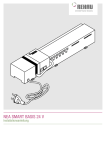
Manual MIRO GSM Safety Description Installation Software Run Mode Configuration Remote Access Technical Data Accessories Manual MIRO GSM Publisher's Note User Manual for MIRO GSM DI6 DO4R 24 VDC Art. No. 52530 MIRO GSM ADI6 DO4R 24 VDC Art. No. 52531 MIRO GSM DI6 DO4R 230 VAC Art. No. 52532 Version 1.3 Edition 11_11 EN Article Number 52536 Murrelektronik GmbH Falkenstrasse 3 D-71570 Oppenweiler Phone +49 (0) 71 91 47-0 Fax +49 (0) 71 91 47-130 [email protected] 3 Manual MIRO GSM Service and Support Website: www.murrelektronik.com In addition, our Customer Service Center (CSC) will be glad to assist you: The CSC supports customers over the entire course of the project, during planning and the conception of customer applications, configuration, installation, and start-up. We also offer competent consulting or – in more complex cases – we even provide direct onsite support. The CSC supplies support tools. It performs measurements for fieldbus systems, such as Profibus DP, DeviceNet, CanOpen, and AS interface, as well as energy, heat, and EMC measurements. Our coworkers at the Customer Service Center provide their competence, know-how, and years of experience. They are familiar with how products made of various hardware and software manufacturers interact. You can contact the Customer Service Center at telephone number +49 (0) 71 91 47-424 or by email at [email protected]. 4 Manual MIRO GSM Table of Contents Publisher's Note ...................................................................................................................................... 3 Service and Support ................................................................................................................................ 4 Table of Contents .................................................................................................................................... 5 Important Information .............................................................................................................................. 7 1. Safety .................................................................................................................................................. 8 1.1 Intended Purpose .......................................................................................................................... 8 1.2 Qualified Personnel ....................................................................................................................... 8 1.3 Safety Instructions ......................................................................................................................... 9 2. Description......................................................................................................................................... 11 2.1 Short Description of the MIRO GSM ........................................................................................... 11 2.2 Application Examples .................................................................................................................. 12 2.3 Short Instructions ......................................................................................................................... 12 3. Installation / Scope of Supply ............................................................................................................ 15 3.1 Selecting the Antenna.................................................................................................................. 15 3.2 Installation .................................................................................................................................... 15 3.2.1 Connecting the Inputs ........................................................................................................... 16 3.2.2 Connecting the Outputs ........................................................................................................ 16 3.3 TEST and RESET Buttons .......................................................................................................... 17 4. Software ............................................................................................................................................ 18 4.1 System Requirements ................................................................................................................. 18 4.2 Software Installation .................................................................................................................... 19 5. Run Mode .......................................................................................................................................... 20 5.1 LED State Display ........................................................................................................................ 20 5.1.1 GSM LED .............................................................................................................................. 20 5.1.2 State LED .............................................................................................................................. 20 5.1.3 Inputs and Outputs ................................................................................................................ 21 5.2 Power Failure ............................................................................................................................... 21 5.3 Diagnostics .................................................................................................................................. 22 5.4 State Request .............................................................................................................................. 23 6. Configuration ..................................................................................................................................... 24 6.1 General Information ..................................................................................................................... 24 6.2 Managing the Phone Book .......................................................................................................... 24 6.2.1 Phone Numbers .................................................................................................................... 24 6.2.2 Email Address ....................................................................................................................... 24 6.2.3 Settings ................................................................................................................................. 26 6.2.4 Automatic Network Provider Search ..................................................................................... 27 6.2.5 Manual Provider Search........................................................................................................ 27 5 Manual MIRO GSM 6.2.6 Device Identification .............................................................................................................. 27 6.2.7 Activating Remote Access .................................................................................................... 28 6.2.8 Disabling Local Access ......................................................................................................... 28 6.3 State Messages ........................................................................................................................... 29 6.4 Input Configuration ...................................................................................................................... 31 6.4.1 General Information .............................................................................................................. 31 6.4.2 Digital Inputs (MIRO GSM DI6 DO4R 24 VDC, Art. No. 52530 and MIRO GSM DI6 DO4R 230 VAC, Art. No. 52532) .............................................................................................................. 31 6.4.3 Parallel Message Handling ................................................................................................... 32 6.4.4 Time-delayed Messages on Signal Reception...................................................................... 32 6.4.5 Time-delayed Messages on Output OFF .............................................................................. 33 6.4.6 Analog Inputs (MIRO GSM ADI6 DO4R 24 VDC, Art. No. 52531) ....................................... 33 6.4.7 Scaling and Unit .................................................................................................................... 34 6.4.8 Messages and Limit Definition .............................................................................................. 35 6.4.9 Message Delay ..................................................................................................................... 40 6.4.10 Message Block .................................................................................................................... 41 6.5 Configuring the Outputs ............................................................................................................... 41 6.5.1 General Information .............................................................................................................. 41 6.6 Time Function .............................................................................................................................. 42 6.7 CALL-IN Function ........................................................................................................................ 43 7. Remote Access ................................................................................................................................. 43 7.1.1 General.................................................................................................................................. 43 7.2 Configuring Remote Access ........................................................................................................ 44 7.3 Connection Set-up ....................................................................................................................... 45 7.4 I/O State Request ........................................................................................................................ 48 7.4.1 Digital Inputs ......................................................................................................................... 49 7.4.2 Analog Inputs ........................................................................................................................ 49 7.4.3 Outputs .................................................................................................................................. 50 7.5 Selecting the Language ............................................................................................................... 50 7.5.1 General Information .............................................................................................................. 50 8. Technical Data................................................................................................................................... 51 8.1 Dimensional Layout ..................................................................................................................... 51 8.2 Technical Data ............................................................................................................................. 52 9. Accessories ....................................................................................................................................... 56 Overview of Devices and Phone Numbers ........................................................................................... 57 Legal Provisions .................................................................................................................................... 58 6 Manual MIRO GSM Important Information Important instructions in this Manual are indicated by the use of colors and are marked accordingly. DANGER Immediate danger Failure to observe this warning will immediately result in death or severe personal injury. WARNING Possible danger Failure to observe this warning may possibly result in death or severe personal injury. CAUTION Low risk hazard Failure to observe this instruction will lead to personal injury of light to medium severity. Note Notes indicate important information. Instructions highlighted in green are recommendations issued by Murrelektronik. 7 Manual MIRO GSM 1. Safety 1.1 Intended Purpose The products that are described in this manual were developed, manufactured, tested, and documented in compliance with the relevant safety standards. In normal cases, these products do not constitute any danger to persons or objects, provided the handling specifications and safety instructions described in this manual are observed. The products comply with the requirements of EMC Directive 2004/108/EG and standards EN 61000-6-2 and EN 61000-6-3. WARNING This device is not suitable for monitoring sensitive plants or time-critical processes. GSM network failures or interruptions in power supply may disturb supervision safety and reliability. Do not use the OFF state of the outputs to implement safety-related requirements of the system/machine. The products are designed for industrial use. An industrial environment is defined as one in which loads are not connected directly to the public low-voltage power grid. Additional measures must be taken if the products are used in private, business, or trade environments. Operating the device in accordance with its intended purpose is only assured when it is fully mounted. The power supply must comply with SELV1 or PELV2. Power sources in accordance with EN 61558-26 (transformers) or EN 60950-1 (switched-mode power supply) meet these requirements. WARNING This device may not be installed in explosion-hazard zones or in the vicinity of medical equipment. 1.2 Qualified Personnel Only qualified, trained electricians knowledgeable in the safety standards of automation systems may configure, install, set up, service, and test the devices. 1 2 Safety Extra Low Voltage Protective Extra Low Voltage 8 Manual MIRO GSM The requirements concerning qualified personnel are dependent on the requirements profiles described in ZVEI and VDMA publication Only electricians who know the contents of this manual may install and maintain the products described here. "Weiterbildung in der Automatisierungstechnik“(Further training in automation systems), published by ZVEI and VDMA in the Maschinenbau-Verlag, P.O.Box 710864 in D-60498 Frankfurt, Germany. They are therefore persons who are capable of assessing the work executed and any possible dangers arising from this due to their professional training, knowledge, experience, and their knowledge of the relevant standards, or the same level of knowledge from a similar field, or after doing technical training. Only Murrelektronik technical personnel are allowed to execute work on the hardware and software of our products, provided they are devices not described in this manual. WARNING Electrical hook-up, start-up, and operation of this device may only be performed by qualified personnel. WARNING Tampering with the hardware or software, or failure to observe the warning instructions may result in severe personal injury or damage to assets. Never tamper with hardware or software. Comply with the warning instructions. 1.3 Safety Instructions WARNING Make sure you read the operating instructions. The safe, troublefree functioning of the product requires proper transportation, storage, mounting, and installation, and careful operation. Current safety and accident prevention laws valid for the specific application must be observed for the configuration, installation, setup, servicing, and testing of the devices. 9 Manual MIRO GSM Only use cables and accessories that meet the requirements and regulations for safety, electromagnetic compatibility, and, if necessary, the specifications for telecommunications terminal equipment. Make absolutely sure when you hook up to the 230 VAC power source that the power supply and the power to the inputs stem from the same outer conductor. Do not allow a voltage exceeding 240 VAC to access the device itself. Only fit or remove the MIRO GSM when it is in deenergized state. Comply with the regulations and customary standards when you perform the electrical installation of the device. Installation must be performed by a competent person. Note The card owner bears the sole responsibility for protection against misuse of the SIM card. Note Murrelektronik GmbH assumes no liability for any injury to persons or damage to buildings and/or machines arising from faulty operation or from failure to comply with the instructions. Murrelektronik GmbH assumes no responsibility for use of the MIRO GSM or its operation. In particular, Murrelektronik GmbH guarantees no connection reliability to the mobile network, neither do we guarantee there will be no network failures. 10 Manual MIRO GSM 2. Description 2.1 Short Description of the MIRO GSM The MIRO GSM from Murrelektronik is a remote-control and messaging system. It has six inputs, which can be configured as analog or digital inputs, and four relay outputs with switchover contacts. All the inputs and outputs can be monitored by SMS (Short Message System) over any mobile radio network*. The service provider decides on the SIM card. The device’s own phone book saves up to 50 mobile phone numbers and names of message receivers. Each state change at one of the inputs sends a predefined message by SMS to the assigned receivers. The receivers are processed cyclically one by one, according to the selected sequence. The outputs can be switched ON and OFF by SMS containing predefined messages. In order to obtain an overview of the present state of all inputs and outputs of the installation, the input and output states can be queried by SMS. The relay outputs can be linked to a “timer function“ and can be switched time-dependent for a preset period. The password option prevents unauthorized remote access to MIRO GSM by third parties. MIRO GSM sends out a message at regular intervals automatically, for example, the MIRO GSM sends out a message in case of power loss. When power is restored, the MIRO GSM announces its operational state again with a new message. All input and output states can be attached to each message. Programming the MIRO GSM is carried out using the "MIRO GSM Configuration Software“ that is supplied together with the device. All the settings can be configured very easily and without special knowledge of any programming language. * Mobile radio network: 850 MHz, 900 MHz, 1800 MHz, 1900 MHz (quad band GSM module inside) 11 Manual MIRO GSM 2.2 Application Examples Heating control Pump control Irrigation installations Alarm transmission Level monitoring Temperature monitoring Pressure monitoring Valve control Voltage monitoring Fault signals from machines and installations of all types and many more Fig. 1: Application examples 2.3 Short Instructions Note Installation requirements: The MIRO GSM must be disconnected from the power source when it is installed. 1. Snap the MIRO GSM on to the mounting rail. 2. Hook up the MIRO GSM as described in the connection diagrams on pages 16 to 16. 3. Open the front cover and insert the SIM card. Fig. 2: Remove the front cover Fig. 3: SIM card, RS232 interface 12 Manual MIRO GSM 4. Caution: Make sure the voltage is correct. The MIRO GSM then starts its initialization routine. 5. Caution: Do not access the MIRO GSM. 6. Load the MIRO GSM Configuration Software (Service and Start-up Kit Art. No. 52535, or download from www.murrelektronik.com). 7. Connect the RS232 interface of your PC or notebook to the programming interface of the MIRO GSM. Fig. 4: Connecting a PC or notebook with RS232 interface Note If there is RS232 slot, use the one supplied in the Service and Start-up Kit (Art. No. 52535) or a commercially available USB RS232 converter (do not forget to install the driver). Fig. 5: Connecting a PC or notebook without RS232 interface 13 Manual MIRO GSM 8. Start the MIRO GSM Configuration Software. 9. Create a new configuration or open an existing one. Save your configuration locally on your PC or notebook. 10. Enter the correct PIN code. This is absolutely necessary for the first installation. Once the MIRO GSM is initialized, the state LED and GSM LED flash regularly at the rate of one second (after approx. 100 s). 11. Write the configuration you generated to the MIRO GSM. 12. Select a free COM port (menu option: Configuration => Select Port). The COM port can be found under Windows in the Control Panel under System / Hardware / Connections. 13. Download the file to MIRO GSM. 14. Wait approx. 100 s until the MIRO GSM is ready, i.e. the state and GSM LEDs flash at a rate of 3 seconds. 15. Set the clock (menu option: Configuration => Set Clock). 14 Manual MIRO GSM 3. Installation / Scope of Supply 3.1 Selecting the Antenna When ordering, observe the following points and check them previously using a mobile phone. Check the strength of the transmitted signal from the selected provider before ordering the antenna. The MIRO GSM is supplied without antenna. In the switch cabinet, the MIRO GSM Outdoor Antenna Art.No. 52534 provides much better results than the stub antenna Art. No. 52533. Note When selecting the antenna, take the installation location into consideration. The MIRO GSM Stub Antenna Art. No. 52533 is not suitable for integration in a switch cabinet (due to the shielding). Fig. 6: MIRO GSM Stub Antenna Fig. 7: MIRO GSM Outdoor Art. No. 52533 Antenna Art. No. 52534 3.2 Installation WARNING Electrical hook-up, start-up, and operation of this device may only be performed by qualified personnel. Make sure you read the operating instructions. Failure to observe the instructions may lead to severe personal injury and/or damage to assets. 15 Manual MIRO GSM CAUTION Make absolutely sure when you hook up to the 230 VAC power source that the power supply and the power to the inputs stem from the same line conductor. A voltage of > 240 VAC may not be applied to the device. CAUTION Only fit or remove the MIRO GSM when it is in deenergized state. The MIRO GSM is isolation-protected and does not require grounding. Connect the MIRO GSM according to the schematic diagram below. 3.2.1 Connecting the Inputs Fig. 8: Connecting the MIRO GSM DI6 DO4R 230 VAC Art. No. 52532 digital inputs Fig. 9: Connecting the MIRO GSM DI6 DO4R 24 VDC Art. No. 52530 digital inputs Fig. 10: Connecting the MIRO GSM ADI6 DO4R 24VDC Art. No. 52532 with either analog or digital inputs 3.2.2 Connecting the Outputs Fig. 11: Connecting the outputs, all variants 16 Manual MIRO GSM 3.3 TEST and RESET Buttons TEST button (the right button when viewed from the front) If you press the TEST button for more than 5 seconds, a test message is sent. RESET button (the left button when viewed from the front) All relay outputs are reset when the button is pressed for longer than 15 s in its home position. This means for the first switchover contact: 12-14 open / 12-13 closed. The characteristic of all switchover contacts is identical. Fig. 12: TEST and RESET buttons 17 Manual MIRO GSM 4. Software 4.1 System Requirements The MIRO GSM Configuration Software runs on the current Microsoft operating systems. The following minimum system requirements must be met for the software to function properly: Operating systems Windows2000, WindowsXP, WindowsVista, Windows7 CPU capacity Pentium II / 166 MHz, recommended: Pentium III / 800 MHz RAM 256 MB (WindowsXP) Hard disk storage capacity 40 MB requirement Programming interface RS232 USB (with USB RS232 interface converter) Screen resolution* Minimal: 1024 x 768 Pixel *Please note: If the screen resolution is too low, the window of the programming software will not be displayed in the normal size. This means some tabs or buttons may be outside the screen window and therefore illegible. Procedure: Change the screen resolution by selecting “Start” – “Control panel” – “Display” and then the “Settings” tab. Please set the screen resolution to a minimum of 1024 x 768 pixels. Fig. 13: Setting the screen resolution 18 Manual MIRO GSM 4.2 Software Installation The installation menu starts automatically when you insert the CD ROM in the CD drive. If this is not the case, then start the CD-ROM by double-clicking on "Start" in Windows® Explorer. Start right mouse button Explorer My Computer Device with removable drives setup.exe. If no CD ROM available, the software is available for free download from the Murrelektronik website at www.murrelektronik.com. PC synchronization programs for mobile phones (eg Nokia Ovi Suite), can occur compatibility problems with the MIRO GSM Configuration software. In this cases, please contact us. The installation menu is available in different languages. Please choose the required language. The Configuration Software is loaded onto your computer. Please follow the set-up programming instructions during installation. The MIRO GSM starts up automatically after power is applied. If the signal is strong enough, the device registers itself in the GSM network (dependent on the SIM card settings, dependent on the provider). The two LEDs display the actual device and network states (see Chapter 5). 19 Manual MIRO GSM 5. Run Mode 5.1 LED State Display The MIRO GSM has two LEDs, the GSM LED, and the state LED. The two LEDs are visible from the outside and are located below the cover. The following states are indicated: 5.1.1 GSM LED State Rate Meaning Flashing regularly 1s Module is not registered in the GSM network. Brief flashing approx. Module is registered and ready for data transmission. 3s Irregular flashing Data are transmitted (SMS). Tab. 1: GSM LED displays 5.1.2 State LED State Rate Repetition LED dark Meaning Device is not running. Intermittent flashing Irregular Device is running up. Brief flashing approx. 3 s 1x Device in running, everything OK. Brief flashing approx. 3 s 2x No credit left Brief flashing approx. 3 s 3x Clock not set. Regular flashing 1s 1x Module in initialized state. Regular flashing 1s 2x Configuration error of SIM blocked Regular flashing 1s 3x Communication error Tab. 2: State LED displays For further explanations of errors and their rectification, see "5.3 Diagnostics". 20 Manual MIRO GSM 5.1.3 Inputs and Outputs Each input and output state is displayed by individual LEDs. These LEDs are designated as follows: Inputs 1, 2, 3, 4, 5, 6 (LED lights up = input switched on) Outputs1, 2, 3, 4 (LED lights up = output switched on) Fig. 14: LEDs on the MIRO GSM 5.2 Power Failure Short power supply failures (t < 1s) are tolerated and do not change the module state. Longer power failures (t > 1s) are registered and can trigger a last SMS alarm message (depending on the mode setting) before the device shuts down. The device restarts automatically after the power supply is restored. The registration of the MIRO GSM in the GSM network is restored and the same state of the outputs is initiated as before the power failure (memory function). Note The relays have monostable outputs. They are in their home position during power off, e.g. Contact 11-14 open / Contact 11-12 closed. After power is restored, the contacts are in the same position as before the power failure. 21 Manual MIRO GSM 5.3 Diagnostics The MIRO GSM in conjunction with the Configuration Software allows the display of the actual signal strength. To achieve this, the MIRO GSM must be connected to a PC / notebook by the programming cable. The diagnostic routine is accessible using menu option "Options – Diagnose". In addition to the signal quality, the diagnostics displays more information, such as version numbers, error codes, and service provider. Fig. 15: "Diagnose" window The table below shows the error codes and their meaning. Code Meaning Cause Remedial Action 1 No credit Pre-paid card empty Load SIM card 2 Time not set Time not set Set time manually using menu option "Options – Settings: Date / Time", or send an SMS to the MIRO GSM. 3 No Device is not configured. Write configuration. Configuration Configuration faulty or incompletely Repeat file loading. error saved. Communication error An SMS was not sent completely Check receive signal strength: since there was no reception, or the Check SIM card validity. device was not registered in the Procedure: Insert SIM in a mobile network. phone (cell phone) and send an SMS configuration 4 5 to a call number. 22 Manual Code 1001 MIRO GSM Meaning Cause Remedial Action SIM card blocked PIN code was entered incorrectly 3 Insert the SIM card in a mobile phone times. Enter PUK to clear Replace SIM card in replay. 1002 No SIM card. SIM card missing or soiled. Insert SIM card or clean SIM contacts: Tab. 3: Error codes and their meaning 5.4 State Request When the PC is connected to MIRO GSM, the current state of the inputs and outputs of the MIRO GSM can be requested. The state can also be requested by remote access (see Chapter 7). 23 Manual MIRO GSM 6. Configuration 6.1 General Information The MIRO GSM is configured and prepared for use by a PC or notebook using the MIRO GSM Configuration Software. Before, the MIRO GSM may be prepared for installation, i.e. the MIRO GSM can be configured (create phone book, enter messages) without connection to the device. Do this by starting the software, creating a new file, or opening an existing file and editing it. Save the resulting file under a new file name. Then send it to the MIRO GSM over the programming cable MIRO GSM RS232. The diagnostic function is not active in offline mode. You can only access the diagnostic function when the MIRO GSM is connected to the PC via the serial RS232 interface. You can use the MIRO GSM to perform remote maintenance over a GSM link. For this, you require the MIRO GSM Configuration Software. See Chapter "7. Remote Maintenance" which describes the requirements for connection set-up and operation in more detail. 6.2 Managing the Phone Book The software offers the option to register and manage up to 50 telephone numbers or email addresses. The next section describes how to manage phone book entries. 6.2.1 Phone Numbers Add Edit Delete Enter a new phone number. Edit an existing entry. Delete an existing entry. Please enter the phone number in international format (i.e. with country code and prefix) with no blanks, e.g.. +497191470 (+49 Germany, +41 Switzerland; +31 the Netherlands, etc.). 6.2.2 Email Address First, activate the email function in the field "Activate email" and enter the provider's service number. Enter the email addresses using the procedure below: Add Edit Delete Enter a new email address. Edit an existing entry. Delete an existing entry. Please enter email addresses in the format [email protected]. 24 Manual MIRO GSM Fig. 16: Phone book entry Note Not all special characters can be used for SMS messages. The characters are recognized by the programming software and displayed in an error window. The error characters must then be deleted. The "Name" data field can sort the list alphabetically in ascending or descending order. Sorting has no impact on existing entries. Overwrite the "Default" with a user entry. 25 Manual MIRO GSM 6.2.3 Settings The default settings for SMS transmission contain important general data which help to identify the device or the installation. This is where remote access is enabled (for a description, see Chapter "7. Remote Access"). The SIM card is protected by PIN code just as a regular cell phone. For more information, please refer to the supplement supplied with the SIM card. It describes procedures, such as how you can clear a blocked SIM card after entering an incorrect PIN three times. To do this, remove the SIM card from the MIRO GSM and insert it in a cell phone (mobile phone). Then clear the card according to the specifications of the network operator. Fig. 17: MIRO GSM settings 26 Manual MIRO GSM 6.2.4 Automatic Network Provider Search The automatic network provider selection depends on the SIM card inserted in the MIRO GSM. The provider data and rights stored on the SIM card are accepted. Basically, the provider is preassigned when the SIM card is purchased. Due to the "Automatic" setting, the device searches automatically for the network provider. This is useful when the card is used in the home network. Other GSM networks can be accessed abroad using the same SIM card, depending on the roaming contracts. 6.2.5 Manual Provider Search In manual provider searches, the available GSM networks are scanned several times. The results of this search are displayed with a list of networks. Click on "Search" to display the available networks. Then select the required network. The SMS service center number in contained in the SIM card documentation. Normally, this number is already saved on the SIM card. The number is dependent on the GSM provider. 6.2.6 Device Identification The MIRO GSM can be named in the "Device Description“ field. All messages sent from this MIRO GSM are identified by the name entered in the first line. Device identification can be deactivated. Then, messages are sent without this identification . Note Not all special characters can be used for SMS messages. The characters are recognized by the programming software and displayed in an error window. The error characters must then be deleted. 27 Manual MIRO GSM 6.2.7 Activating Remote Access The remote access function allows the user to edit the configuration of the MIRO GSM remotely, or to send remote requests, or to switch outputs. Changes and edits need not be carried out locally. They can be performed remotely via a GSM link. A remote access password protects against unauthorized access. Note Remote access can only be activated from a PC using the serial cable interface (RS232). CAUTION Remote access can be deactivated by remote access. The device can then no longer be accessed or configured over the GSM network. Re-activation must then be executed locally using a serial cable. Warning "Deactivate Remote Access" 6.2.8 Disabling Local Access Use "Disable local access" to protect access via a serial cable (RS232) by password. This password also applies to remote access. 28 Manual MIRO GSM 6.3 State Messages The receivers of state messages can be chosen from the telephone book. To do this, click the mouse pointer on the expand arrow and select the required entry. The MIRO GSM can send the following state messages: Remote enquiry of all inputs and outputs The device includes an option to interrogate all input and output states by SMS. A code word is then sent by SMS to the device. The code word can be changed. The default code word is: ?#all The reply is sent to the requesting call number (call number identification). The object identification, in this case MIRO GSM, appears at the start of the reply. MIRO GSM I=001001 Q=0101 V1.4.5 SPIOS=1.7.0 HW=2.1 SN=358244014610861 16.09.2009 15:38 The states of the inputs and outputs are mapped in the SMS message as follows: I:001001 inputs 1 to 6 0 = OFF / 1 = ON O:0101 outputs 1 to 4 0 = OFF / 1 = ON If inputs on the MIRO GSM are configured as analog inputs, the device sends the analog values together with their unit. The analog-configured inputs are identified by "-". The state message then looks like this, e.g. when inputs 12 and 15 are analog inputs: MIRO GSM I=0-00-0 Q=0000 21.3m3/h,126lt V1.4.5 SPIOS=1.7.0 HW=2.1 SN=358244014610861 16.09.2009 15:38 I: 0-10-1 O:0101 21.2m3/h,126lt I: 0-10-1 inputs 1 to 6 0 = OFF / 1 = ON / O: 0101 outputs 1 to 4 0 = OFF / 1 = ON - = analog 29 Manual MIRO GSM Attach state of all inputs and outputs to each message This options attaches the state of all inputs and outputs to each message. Periodic message The periodic message is intended for function checking and confirms device functionality. A message is sent periodically. The message can be sent daily (time), weekly (time, weekday), or monthly (time, date). The message text can be edited. The message also contains the current state of the inputs and outputs if they are activated. Message at the start This message is sent to the pre-assigned phone numbers at each start-up (switch on / power restore). The message text can be edited. Message in case of power failure This message is sent to the pre-assigned phone numbers in case the MIRO GSM suffers a power failure. The message text can be edited. Note Not all special characters can be used for SMS messages. The characters are recognized by the programming software and displayed in an error window. The error characters must then be deleted. Trailing Message Info The trailing information of each message (date, time, remaining credit) can be activated or deactivated in the field Trailing Message Info located in the Settings tab. Fig. 18: Trailing Message Info 30 Manual MIRO GSM 6.4 Input Configuration 6.4.1 General Information The MIRO GSM has 6 inputs. These inputs can be activated as digital (MIRO GSM DI6 DO4R 24 VDC, Art. No. 52530 und MIRO GSM DI6 DO4R 230 VAC, Art. No. 52532), or digital / analog (MIRO GSM ADI6 DO4R 24 VDC, Art. No. 52531). 6.4.2 Digital Inputs (MIRO GSM DI6 DO4R 24 VDC, Art. No. 52530 and MIRO GSM DI6 DO4R 230 VAC, Art. No. 52532) Each of these inputs can send a freely definable SMS message to a maximum of five pre-assigned phone numbers when the input signal is HIGH or LOW. Note Please note that every input must be assigned with at least one phone number selected from the list of receivers. It is irrelevant whether the input is connected or not. If the receiver list is empty, the configuration can not be saved. Basically, two events can trigger an SMS message: a change from "LOW" to "HIGH", and the inverse, a change from "HIGH" to "LOW". One or both events can be configured to activate a message. A separate message text can be entered for each event. If the confirmation function is activated, and the MIRO GSM receives no receive acknowledgement SMS from the receiver within the preset timeout, the event message is sent to the next receiver. The MIRO GSM runs through the assigned receiver phone number cyclically and then starts again with the first phone number. A maximum of five loops can be defined. As soon as the device receives a confirmation, the process is stopped. If this is not the case, the message is sent to the next receiver on expiry of the preset timeout. If the confirmation function is not activated, all the assigned receivers receive a message without repetition simultaneously. If the confirmation code word is not activated, the phone number identification is carried out as a security check, and it is sufficient to send an empty SMS message to the MIRO GSM. 31 Manual MIRO GSM Note Not all special characters can be used for SMS messages. The characters are recognized by the programming software and displayed in an error window. The error characters must then be deleted. 6.4.3 Parallel Message Handling It may occur that the state of several inputs change at the same time or within the actual running message cycle. Every input activates its individual message. Every change of the input state, which triggers an event message, is processed in order of their appearance (device-internal). Several different messages can therefore be triggered simultaneously. For example, the two events “pump breakdown” and “overtemperature” (two separate inputs) may be signaled at the same time. The two events are processed individually and the two messages are sent one after the other. Fig. 19: Configuration of digital inputs 6.4.4 Time-delayed Messages on Signal Reception If an input signal occurs, the message can be transmitted time-delayed, i.e. the MIRO GSM only sends the predefined message after the preset time elapses and if the signal remains ON constantly during 32 Manual MIRO GSM that time. In other words, the input signal is ignored during the set delay time. This prevents instable input signals, or input impulses that occur repeatedly, to send identical SMS messages several times. Time delays can be set between 0.1 seconds and 99.9 hours. Note It is recommended to activate the delay function (prevents the transmission of several SMS messages for the same event). 6.4.5 Time-delayed Messages on Output OFF If an input changes its state from "HIGH" to "LOW", a delayed message can also be activated. The MIRO GSM sends the predefined message after the preset time elapses and provided the affected input is still "LOW". This prevents instable input signals, or input impulses that occur repeatedly, to send identical SMS messages several times. Time delays can be set between 0.1 seconds and 99.9 hours. Note It is recommended to activate the delay function (prevents the transmission of several SMS messages for the same event). 6.4.6 Analog Inputs (MIRO GSM ADI6 DO4R 24 VDC, Art. No. 52531) The 6 inputs can be individually configured as digital or analog inputs. For this purpose, each input must be defined explicitly as an analog or digital input. The analog inputs are designed for a standardized 0 to 10 VDC analog signal. The resolution here is 12.5 mV across the whole range. 33 Manual MIRO GSM Fig. 20: Configuration of analog inputs 6.4.7 Scaling and Unit In a first step, the measuring unit and the scale must be defined. Two values (MinValue and MaxValue) are assigned to the two end-values 0 V and 10 V. A linear interpolation is carried out between these two values. The resulting linear function (a straight line between two end values) is displayed in the configuration window and is adapted continuously to the entered values. The values entered can be displayed in various decimal formats. The following display types are selectable: d integer value, e.g. 520 d.d one digit after the decimal point, e.g. 520.0 d.dd two digits after the decimal point, e.g. 520.00 d.ddd three digits after the decimal point, e.g. 520.000 Ten characters are available to label the units. This unit is sent with every value message following the actual value. Example of a message: The house temperature is 15.5C 34 Manual MIRO GSM Note Not all special characters can be used for SMS messages. The characters are recognized by the programming software and displayed in an error window. The error characters must then be deleted. Fig. 21: Excerpt from "Scaling and Unit" Fig. 22: Range and limits The value between MaxValue and MinValue is the range R. This range has an important function in defining the thresholds. 6.4.8 Messages and Limit Definition The upper and lower limits must be defined to permit the sending of messages. These limiting values depend on the installation which is monitored. However, certain rules must be obeyed so that the limits are easily recognizable in the scale window. First, the measuring range is calculated. The range is the span between MaxValue and MinValue. The two values correspond to the end values of the analog signal (0 to 10 V) and must be entered. The calculated amount of the measuring range is positive. │Range R│ = │MaxValue – MinValue│ 35 Manual MIRO GSM The maximum Upper Level uLevmax is calculated as follows: Deduct 5% of the range from MaxValue. This results in the maximum upper level uLevmax uLevmax = MaxValue - (│R│ x 0.05) Values entered above this value are corrected automatically by the software. The minimum Lower Level lLevmin is calculated as follows: An amount of 5% of the range is added to the MinValue. This results in the minimum lower level lLevmin lLevmin = MinValue + (│R│ x 0.05) Values entered below this value are corrected automatically by the software. Example: MaxValue: 600 m3/h corresponds to 10 V of the analog signal MinValue: 150 m3/h corresponds to 0 V of the analog signal │Range R│ = │MaxValue – MinValue│= │600 m3/h – 150 m3/h│= 450 m3/h uLevmax = MaxValue - (│R│ x 0.05) = 600 m3/h – (450 m3/h x 0.05) =577.5 m3/h 9.5 V lLevmin = MinValue + (│B│ x 0.05) = 150 m3/h + (450 m3/h x 0.05) =172.5 m3/h 0.5 V The following states may then occur or be monitored: 1 Upper Limit 2 Lower Limit 3 Fig. 23: Excerpt from "Messages" 36 Manual MIRO GSM The present measured value is greater than the upper limit. The system is not in its normal state. The upper limit is exceeded. A message is sent (if this is activated by ). The message text is freely configurable. Upper UpperLevel Level Event Delay time ON Message lock time ON Event (delayed) 1 2 SMS message Fig. 24: Analogue value processing: The measured value is above the upper level. The present measured value lies between the Upper and Lower Levels. The installation is (again) in normal state. A message is only sent if it is activated by , and if the state is occurs, i.e. the upper limit or lower limit was exceeded. The message text is freely configurable. The present measured value is smaller than the lower limit. The monitored installation is not in normal state. The lower limit was exceeded. A message is sent (f this is activated by . The message text is freely configurable. 37 Manual MIRO GSM Lower Level Event Delay time ON Message lock time ON Event (delayed) 3 2 SMS message Fig. 25: Analogue value processing: “Value is smaller than the lower level” The change in value (difference) of the present measured value is exceeded compared to the last measured value sent The MIRO GSM monitors the analog measured value. A message is sent if the difference is activated by and the difference exceeds a certain value. The maximum value here is 50% of the range. Note Values entered above this value are corrected automatically by the software. 38 Manual MIRO GSM Periodic Messages The MIRO GSM can send a present measured value by SMS periodically at intervals of days, weeks, or months. The periodic message is sent to the first receiver. If the receiver fails to acknowledge receipt of the message, the message is sent to the next receiver. All message texts can be freely edited. The measured value and the unit are always transmitted after the message text. A blank is inserted automatically between the message text and the value. No blank is inserted between the value and the unit. Fig. 26: Example for “Periodical messages” Requesting a Value The present value can be requested by SMS. The message text is freely definable. To start a request, an SMS must first be sent to the MIRO GSM. The message must contain the exact wording of the request text. The request text is freely definable. The reply text can also be defined. The measured value and the unit are always transmitted after the reply text. A blank is inserted automatically between the reply text and the value. No blank is inserted between the value and the unit. Fig. 27: Example for “Request value” 39 Manual MIRO GSM Confirmation If the confirmation function is activated, but the MIRO GSM fails to receive a receive confirmation from the receiver within the set timeout, the event message is sent to the next receiver. This means that the device works through the assigned receiver phone numbers (maximum five) cyclically and then starts with the first phone number again. A maximum of five loops can be defined. As soon as the device receives a confirmation, the process is stopped. If this is not the case, the message is sent to the next receiver when the preset timeout elapses. If the confirmation request is not activated, all the receivers assigned to this action receive a message with no repetition simultaneously. If the confirmation password is not activated, the phone number identification is used as a security check, and it is sufficient to send an empty SMS message to the MIRO GSM. 6.4.9 Message Delay If a state is reached at the input that requires the sending of a message due to the set criteria, the message is sent with a time delay, i.e. the MIRO GSM only responds after the preset time by sending the predefined message, provided the state persists during this time. In other words, the input signal is ignored during the set delay time. This prevents the device from sending identical SMS messages several times due to instable input signals, or input impulses that occur repeatedly. Time delays can be set between 0.1 seconds and 99.9 hours. Note It is recommended to activate the delay function (prevents the transmission of several SMS messages for the same event). 40 Manual MIRO GSM 6.4.10 Message Block If an event that requires the sending of a predefined message occurs, the timer starts running. During this time no further messages are sent for this input. This prevents the same events from sending several messages to this input. Block times can be set between 0.1 seconds and 99.9 hours. Note It is recommended to activate the block function (prevents the transmission of several SMS messages for the same event). 6.5 Configuring the Outputs 6.5.1 General Information The MIRO GSM has 4 relay outputs (switchover contacts, 10 A, 250 V). The outputs can be controlled by an SMS, i.e. they can be switched ON or OFF. Every output can be controlled individually. The message text is freely definable. The device only responds to precise wording, i.e. the message (switch command) must have the precise text wording as entered. Uppercase and lowercase characters are ignored, but the blanks between the words and other characters must be entered correctly. When the number identification function is enabled, the device responds only to the switch commands from phone numbers entered in the phone book. An output can therefore be switched on or off by SMS. The MIRO GSM then confirms execution of the action after it occurs. Message texts can be written to switch the device on or off. An additional message can be defined if an output is already in the required state and so no action can be executed. These messages are always sent to the sender of the switch command. Default Click on the button to return all ON/OFF commands automatically to the preset factory defaults. 41 Manual MIRO GSM Fig. 28: Configuring the outputs Note Not all special characters can be used for SMS messages. The characters are recognized by the programming software and displayed in an error window. The error characters must then be deleted. 6.6 Time Function Using a time function, an output can be switched off after a certain time without the need for a switchoff command to be sent by SMS. Switching times can be set between 0.1 seconds and 99.9 hours. When the output is switched off after the preset time elapses, a message is sent to confirm this action. If a switch-off command is sent before the preset time elapses, the command is processed. The time function is defaulted to the OFF state and must therefore be enabled. WARNING This device is not suitable for monitoring sensitive plants or time-critical processes. GSM network failures or interruptions in power supply may disturb supervision safety and reliability. 42 Manual MIRO GSM 6.7 CALL-IN Function The CALL-IN function switches on each output by caller ID for the time specified in Section 6.6. The device detects the incoming call and switches the outputs on without accepting the call. The outputs are switched off automatically when the preset time elapses. An action can so be executed without any costs occurring. Note To enable the "Activate Call-In" field, first enable the time-limited output circuit. 7. Remote Access 7.1.1 General The remote access feature can make changes to the configuration using the MIRO GSM. In order to do this, set up a link to the MIRO GSM (data call to the MIRO GSM) via the GSM modem using the MIRO GSM Configuration Software. Changes on the MIRO GSM can now be made in the familiar environment of the Configuration Software. The first start-up must be executed as described in the two sections "1.1 Short Description" and "6. Configuring the MIRO GSM". Only then can you activate the remote maintenance function. You can perform remote maintenance on the MIRO GSM over a GSM link. Note The SIM cards used for remote maintenance (in the MIRO GSM and also in the GSM modem) must be capable of running with CSD. CSD is a special data transmission standard and means Circuit Switched Data. Contact your network provider for the necessary details. 43 Manual MIRO GSM 7.2 Configuring Remote Access Remote access is activated using the MIRO GSM Configuration Software. Remote access is activated in the general settings. Fig. 29: General settings The password protects the remote access function from unauthorized access. Note Remote maintenance must first be activated from a PC over a customary commercial serial cable connection (RS232). CAUTION Remote access can be deactivated over the remote access. The device can then no longer be accessed or configured over the GSM network. Re-activation must then be executed locally using a serial cable. Warning "Deactivate Remote Access" 44 Manual MIRO GSM 7.3 Connection Set-up You need a GSM modem and the MIRO GSM with activated remote access to set up a connection. Connect the model to the PC or laptop. The MIRO GSM itself is already fitted with an integrated modem of this type. Hook up the modem to the PC/laptop. After connection set-up, the PC/laptop can communicate with the modem. Then you can send data over the GSM link to the MIRO GSM or load data on the PC/laptop. Note Call fees are levied for the whole time that the call is set up between the modem and the MIRO GSM (for calls to a device in another country, roaming fees may also be charged). For this reason, the call should be interrupted immediately after data transmission. Note Before call set-up to the device, we recommend you first complete the configuration on the PC before starting data transmission with the device. First select the option Modem configuration so that the MIRO GSM Configuration Software can set up a connection to the MIRO GSM via GSM. The Configuration Software contains a list of a few modem types. These modems were tested and are supported by the software. 45 Manual MIRO GSM Note We advise you to use modems we have tested. We can not guarantee the function of other modem types (under certain circumstances, the user may have to configure other AT command sets for the modem in use). After selecting the modem type you require, enter the PIN for the modem SIM card in the appropriate field. Confirm your inputs by clicking on OK. Fig. 30: Connection settings Then set up the connection to the remote MIRO GSM. Set the remote access to "active" in the menu bar and the menu option Options. Fig. 31: Remote access is "activated" 46 Manual MIRO GSM When you select remote access, the Configuration Software starts to set up a data link via the GSM modem. To set up a data call, the software requests you to enter the phone number of the MIRO GSM and the password for remote access. Fig. 32: Phone number for data call Fig. 33: Progress of "Connection set-up" If connection set-up fails, repeat your attempt to set up the connection. Fig. 34: Error message "Connection failed" When the connection is set up successfully, you can start to work with the Configuration Software as usual as described in the previous sections. Please note that data transmission over the GSM network may take some time. It may take longer than to load data over a serial cable. Note Data transmission via GSM (remote access) takes more time that direct access over the serial cable. Close the GSM link in the reverse order of operations. Here you may use the menu bar (Disconnect remote access) or use the menu option Options. 47 Manual MIRO GSM Fig. 35: Disconnect remote access Fig. 36: Message "Modem connection is terminated" The connection must also be reset after a timeout of 15 mins. In this case, the connection must be restarted. 7.4 I/O State Request After setting up a connection between the modem and the MIRO GSM (remote access or via a serial cable link), the device state can be requested for all inputs and outputs, and for the present analog values. Note If values or settings are modified over the remote request access, it will take a certain time until they appear in the state display. This may be dependent on the request cycle. Note Data transmission via GSM (remote access) takes more time that direct access over the serial cable. Fig. 37: State request 48 Manual MIRO GSM 6 5 1 2 3 4 Fig. 38: I/O state request - display 7.4.1 Digital Inputs 1 2 Digital input ON Digital input OFF 7.4.2 Analog Inputs The measuring bar displays the measured value and specifies the configured unit. The measuring range of the analog signal is between 0 V and 10 V. If the value present at 3 the input is over 10 V, this is displayed in the state request by at the appropriate input. The relevant unit and the entered maximum value are used for the display. If the signal lies within the measuring range, the measuring bars are displayed in 4 proportion to the present measured value, i.e. the minimum value 0 V = 0 m3 and the maximum value 10 V = 100 m3, e.g. the present measured value is 5 V (corresponds to 50 m3) is displayed by half a measuring bar . Other values are displayed accordingly in proportion to the measuring range. 49 Manual MIRO GSM 7.4.3 Outputs 5 The switching state of the outputs is displayed by ON and OFF.. The outputs may be "remote-controlled" by remote access request. Click the mouse on 6 of the corresponding output to switch the output. 7.5 Selecting the Language 7.5.1 General Information The MIRO GSM Configuration Software has the capability of changing languages. The program need not be restarted after selecting a language. Select in the menu option "Options - Change language" and then select the required language from the list in the menu. Fig. 39: Select language 50 Manual MIRO GSM 8. Technical Data 8.1 Dimensional Layout 19 12 ... 48 VDC MIRO GSM 90 D-71570 Oppenweiler MIRO GSM DI6 DO4R 24 VDC Art.No. 52530 C Output 250V / 10A UL US LISTED Out 88 4.5 44 11 Fig. 40: MIRO GSM - dimensional layout 51 Manual MIRO GSM 8.2 Technical Data Art. No. 52530 MIRO GSM DI6 DO4R 24 V DC Art. No. 52531 MIRO GSM ADI6 DO4R 24 V DC Art. No. 52532 MIRO GSM DI6 DO4R 230 V AC Gerätebeschreibung / Device Description Spannungsversorgung 24 V DC bzw. 230 V AC / Supply voltage 24 V DC or 230 V AC 4 Relaisausgänge (Wechslerkontakte) 250 V/10 A / 4 relay outputs (switchover contacts) 250 V/10 A Individuelle SMS-Meldung für jeden E/A / Individual SMS message for each I/O Einfach konfigurierbar per Computersoftware / Easy to configure with computer software Meldung bei Ausfall bzw. Wiederkehr der Speisung / Alarm in case of failure or return of supply State-Anzeige (LED) für jeden E/A / LED state indication for each I/O Fernwartung über GSM-Netz / Remote maintenance via GSM net Anwendung der üblichen SIM-Karten / Use of standard SIM cards unabhängig von Mobilfunknetzanbietern / Independent of mobile network provider Call-in-Funktion / Call-in function 52 Manual MIRO GSM Technische Daten / Technical data 52530 52531 52532 MIRO GSM DI6 DO4R 24 V DC MIRO GSM ADI6 DO4R 24 V DC MIRO GSM DI6 DO4R 230 V AC Speisung / Power Supply Nennbetriebsspannung / nominal operating voltage Betriebsspannung / operating voltage Frequenzbereich / frequency range Stromaufnahme Standby current consumption in standby Leistungsaufnahme / power consumption Einschaltstromstoss / inrush current 12 … 24 V DC 110 … 240 V AC 10 … 60 V DC 85 … 250 V AC approx. 15 mA at 24 V DC approx. 25 mA at 12 V DC 4.2 W 45 … 63 Hz approx. 10 mA at 230 V AC 8 VA / 5 W < 2.6 A, = 0.4ms Digitale Eingänge I1 … I6 / Digital inputs I1 … I6 Ansteuerspannungsbereich AC, DC / control voltage range AC, DC Eingangsspannungsbereich / input voltage range Ansprechschwelle / trigger threshold Hysterese / hysteresis Stromaufnahme / current consumption Zulässiger Reststrom / Permissible leakage current Kabelkapazität / cable capacity Induktive Parallellastenergie / inductive parallel load energy 12 … 48 V DC 110 … 240 V AC 0 … 60 V DC 0 … 250 V AC 9.5 V DC ca. 5 V 1.5 mA / 24 V 85 V AC ca. 20 V 4 mA / 230 V 20 µA 0.9 mA - 50 nF 50 mWs / 1 Hz (2.5 kV) Bedingungen: Eingebucht im GSM-Netz, keine Kommunikation aktiv, Eingänge nicht angesteuert, Ausgänge ausgeschaltet / Conditions: Logged into the GSM net, no communication active, inputs uncontrolled, outputs switched off 53 Manual MIRO GSM 52530 52531 52532 MIRO GSM DI6 DO4R 24 V DC MIRO GSM ADI6 DO4R 24 V DC MIRO GSM DI6 DO4R 230 V AC Analoge Eingänge I1 … I6 / Analog inputs I1 … I6 Eingangsbereich nominal / nominal input range Eingangsbereich effektiv / actual input range Maximale Eingangsspannung / maximum input voltage Auflösung / resolution - 0 … 10 V DC - - 0 … 12 V DC - - 60 V DC - - - Eingangsimpedanz / input impedance - 12 Bit, LBS ca. 12.5 mV 142 k Fehlergrenze, bezogen auf Eingangsbereich / error limit, related to input range Reaktionszeit maximal / max. reaction time Zeitdaten / Time data - 1 - - 1s - Hochlaufzeit Speisung (Ri = 0) / Set-up time supply (Ri = 0) Min. Ansteuerdauer Input (AC, DC) / min. control time input (AC, DC) Netzausfallsicherheit / power failure protection Ausgangskreis / Output circuit Ausgang / output Kontaktart / contact type Nennstrom pro Ausgang / nominal current per output Summenstrom / total current Einschaltstrom / inrush current Nennspannung / nominal voltage Schaltleistung / switching capacity Empfohlene Mindestlast / recommended minimum load Kontaktwerkstoff / contact material Kontaktlebensdauer / contact life Mechanische Lebensdauer / mechanical life Spannungsfestigkeit / electric strength Gerät – Kontakt / device - contact Kontakt – Kontakt / contact contact - 25 s 200 ms 15 ms 4 relay contact Switchover contacts 10 A max. 20 A 15 A / 20 ms 250 V AC 2500 VA AC-1 / …250 W DC-1 10 mA / 12 V AgNi 90/10 150 000 (10 A, 250 V AC-1) 30 x 10 6 2.5 kV (RMS, 1 min) 2.5 kV (RMS, 1 min) 54 Manual MIRO GSM Sonstiges / Other: 52530 52531 52532 MIRO GSM DI6 DO4R MIRO GSM ADI6 DO4R 24 V DC MIRO GSM DI6 DO4R 230 V AC 24 V DC Allgemeine Daten / General data 80 x 90 x 59.5 mm Abmessungen (H x B x T) / dimensions (H x W x D) Noryl SE1, Lexan EXL9330 Gehäusewerkstoff / housing material Screw terminal 2.5 mm², 0.5 Nm, Pozidrive/slot-head Anschluss / connection IP20 Schutzklasse / protection class TS 35 DIN/EN60715, screw fixing M4 Befestigung / attachment approx. 260 g Gewicht / Weight Umgebungsbedingungen / Ambient conditions Lagertemperatur / Storage temperature Betriebstemperatur / operating temperature Relative Feuchte / relative humidity Transientenschutz / transient protection EMV / EMC -40 … +85 °C -25 … +55 °C 10 … 95 % Single impulse 2.5 kV / 2.5 Ws Sicherheit / safety Störfestigkeit / interference immunity Störaussendung / interference emission EN 60730-1:2000 EN 61000-6-2:2005 EN 61000-6-3:2007 Zulassungen / Approvals C UL US LISTED CE Conformitätserklärung / CE declaration of conformity CE-Bezeichnung in Übereinstimmung mit EMV Richtlinie 2004/108/EC und Niederspannungsrichtlinie 2006/95/EC / CE-marking in compliance with EMC directive 2004/108/EC and low-voltage directive 2006/95/EC 55 Manual MIRO GSM 9. Accessories Art. No. 52533 MIRO GSM Stummelantenne / Stub antenna Art. No. 52534 MIRO GSM Außenantenne mit 5 m Kabel / Antenna with 5 m cable Art. No. 52535 MIRO GSM Service- und Inbetriebnahme-Kit / Service and Start-up Kit Art.-No. 52536 MIRO GSM Handbuch / Manual 56 Manual MIRO GSM Overview of Devices and Phone Numbers Devices N° MIRO GSM Device ID Device type A/D PIN Password Phone Number Device type A/D Pin Password Phone Numbers 1 2 3 4 5 6 7 8 9 10 Modem N° MIRO GSM Device ID 1 57 Manual MIRO GSM Legal Provisions Exclusion of Liability Murrelektronik GmbH has checked the contents of this technical documentation for conformity with the hardware and software described therein. Deviations can not be excluded in individual cases. For this reason, Murrelektronik excludes the warranty for the correctness of its contents and any liability for errors, in particular full conformity. The limitation of liability shall not apply if the cause for damage is attributable to willful intent and/or gross negligence, or for all claims arising from the Product Liability Law. Should a major contractual obligation be violated by criminal negligence, the liability of Murrelektronik GmbH shall be limited to damages that typically arise. Subject to technical changes and alternations in content. We advise that you check at regular intervals whether this documentation has been updated since corrections that may become necessary due to technical advances are included by Murrelektronik GmbH at regular intervals. We are gratefully for any suggestions for improvement. Copyright It is prohibited to transfer or photocopy the documentation either in paper or in digital form, reuse or divulge its contents unless otherwise expressly permitted by Murrelektronik GmbH or in conjunction with the production of documentation for third-party products that contain products made by Murrelektronik GmbH. Violations will result in liability for damages. All rights reserved, in particular in the event of the award of patents or granting of utility models. Right of Use Murrelektronik GmbH grants its customers a non-exclusive right revocable at any time and for an indefinite period of time to use this documentation to produce their own technical documentation. For this purpose, the documentation produced by Murrelektronik GmbH may be changed in parts, or amended, or copied ,and transferred to the customer's users as part of the customer's own technical documentation on paper or on electronic media. The customer shall then bear sole responsibility for the correctness of the contents of the technical documentation produced by him. If the technical documentation is integrated in part, or in full in the customer's technical documentation, the customer shall refer to the copyright of Murrelektronik GmbH. Furthermore, special attention shall be paid to compliance with the safety instructions. Although the customer is obliged to make reference to the copyright of Murrelektronik GmbH, provided the technical documentation of Murrelektronik GmbH is used, the customer shall market and/or use the technical documentation on his sole responsibility. The reason is that Murrelektronik GmbH has no influence on changes or applications of the technical documentation and even minor changes to the starting product or deviations in the intended applications may render incorrect the specifications contained in the technical documentation. For this reason, the customer is obliged to identify the technical documentation originating from Murrelektronik GmbH if and inasmuch as the documentation is changed by the customer. The customer shall be obliged to release Murrelektronik from the damage claims of third parties if the latter are attributable to any deficits in the documentation. This shall not apply to damages to the rights of third parties caused by deliberate or criminal intent. The customer shall be entitled to use the company brands of Murrelektronik GmbH exclusively for his product advertising, but only inasmuch as the products of Murrelektronik GmbH are integrated in the products marketed by the customer. The customer shall refer to the brands of Murrelektronik GmbH in an adequate manner if the brands of Murrelektronik GmbH were used. 58 Murrelektronik GmbH|Falkenstraße 3, D-71570 Oppenweiler|P.O. Box 1165, D-71567 Oppenweiler Phone +49 7191 47-0|Fax +49 7191 47-130|[email protected]|www.murrelektronik.com The information in this manual has been compiled with the utmost care. Liability for the correctness, completeness and topicality of the information is restricted to gross negligence.