1
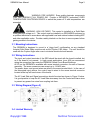
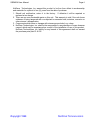
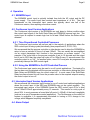
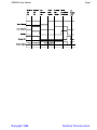
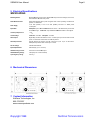
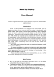
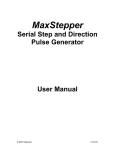
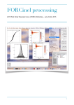
Rev. 6.1 06/10 SSRMON USERS MANUAL SOLID STATE RELAY MONITOR COPYRIGHT 1998 NUWAVE TECHNOLOGIES, INC. SSRMON User Manual Page 2 Table Of Contents 1. 2. 3. 4. 5. 6. 7. Ordering Code (Figure 1) .................................................................................................................................. 2 Description ......................................................................................................................................................... 2 Installation / Safety Information ......................................................................................................................... 2 3.1 Mounting Instructions ................................................................................................................................ 3 3.2 Wiring Instructions .................................................................................................................................... 3 3.3 Wiring Diagram (Figure 2) ........................................................................................................................ 3 3.4 Limited Warranty....................................................................................................................................... 3 Operation ........................................................................................................................................................... 5 4.1 SSRMON Input ......................................................................................................................................... 5 4.2 Continuous Input Version Applications ..................................................................................................... 5 4.2.1 Time Proportioned Controlled Processes ........................................................................................ 5 4.2.2 Using the SSRMON in On-Off Controlled Process .......................................................................... 5 4.3 Interrupted Input Version Applications ...................................................................................................... 5 4.4 Alarm Output ............................................................................................................................................. 5 4.5 Fault Conditions ........................................................................................................................................ 6 4.5.1 Continuous Input Fault Detection ..................................................................................................... 6 4.5.2 Interrupted Input Fault Detection ...................................................................................................... 6 4.6 Input / Output Logic ................................................................................................................................... 6 4.7 Status Diagram (Figure 3) ........................................................................................................................ 6 Electrical Specifications ..................................................................................................................................... 8 Mechanical Dimensions ..................................................................................................................................... 8 Contact Information ........................................................................................................................................... 8 1. Ordering Code (Figure 1) ORDERING INFORMATION SSRMON - Input Mode C: Continuous I: Interrupted Power Supply 12: 12VDC 24: 24VDC For Example: A 240 Volt Line Voltage type with a 5-15V input, 12V power Supply and Continuous mode would be ordered as: SSRMON-C-12 2. Description The SSRMON is an SSR mounted diagnostic module that monitors the SSR for loss of load, loss of power, shorted SSR, etc. The module provides a closed relay contact that opens upon any fault condition. 3. Installation / Safety Information Responsibility for determining suitability for use in any application / equipment lies solely on the purchaser, OEM and end user. Suitability for use in your application is determined by applicable standards such as UL, cUL and CE and the completed system involving this component should be tested to those standards. Copyright 1998 NUWAVE TECHNOLOGIES SSRMON User Manual Page 3 WARNING: FIRE HAZARD!! Even quality electronic components CAN FAIL KEEPING FULL POWER ON! Provide a SEPARATE (redundant) OVER TEMPERATURE SHUTDOWN DEVICE to switch the power off if safe temperatures are exceeded. WARNING: HIGH VOLTAGE!! This control is installed on a Solid State Relay with high voltage on it. This control must be installed in a GROUNDED enclosure by a qualified electrician in accordance with applicable local and national codes including NEC and other applicable codes. Provide a safety interlock on the door to remove power before gaining access to the device. 3.1 Mounting Instructions The SSRMON is designed to mount in a “piggy back” configuration on any standard footprint Solid State Relay module such as the Crydom CSD series. The unit should be used with the Crydom finger-safe cover to minimize electrical shock hazards. 3.2 Wiring Instructions The input and output terminals of the SSR should be wired with the board installed, but as if the board is not present. In high current applications (over 40A) we recommend wiring the connection lugs under the SSRMON Printed Circuit Board Bushings. All I/O on the SSRMON is available with screw terminal connectors for ease of harness assembly. The screw connectors can accept up to 14 AWG wire. The power, alarm, and ground wires are wired to the screw terminal block. In the case of the interrupted input version, the control input is wired to the screw terminal connector located at the top left hand corner of the board. The AC Load Side and Signal connections should be wired as shown in Figure 2 below. It is good practice to keep the AC Load Side wires away from the Control and Alarm wires to prevent any power line noise from coupling into them. 3.3 Wiring Diagram (Figure 2) 3.4 Limited Warranty Copyright 1998 NUWAVE TECHNOLOGIES SSRMON User Manual Page 4 NuWave Technologies, Inc. warrant this product to be free from defect in workmanship and materials for a period of two (2) years from the date of purchase. 1. Should unit malfunction, return it to the factory. If defective it will be repaired or replaced at no charge. 2. There are no user serviceable parts on this unit. This warranty is void if the unit shows evidence of being tampered with or subjected to excessive heat, moisture, corrosion or other misuse / misapplication. 3. Components which wear or damage with misuse are excluded, e.g. relays. 4. NuWave Technologies, Inc. shall not be responsible for any damage or losses however caused, which may be experienced as a result of the installation or use of this product. NuWave Technologies, Inc. liability for any breach of this agreement shall not exceed the purchase price paid E. & O.E. Copyright 1998 NUWAVE TECHNOLOGIES SSRMON User Manual Page 5 4. Operation 4.1 SSRMON Input The SSRMON control input is optically isolated from both the AC output and the DC power supply. The control input has nominal input impedance of ~4 K. The input impedances on the Interrupted input version are typically about one half of the Continuous version, thus requiring more drive current. 4.2 Continuous Input Version Applications The Continuous input version of the SSRMON can only detect a failure condition when the control input signal of the Solid State Relay and SSRMON become logic low. The control input is required to remain logic low for at least 100mS before the failure will be detected. 4.2.1 Time Proportioned Controlled Processes The Continuous input version will perform well in the majority of applications where the SSR control input is being cycled periodically (time proportioned P, PI,PD, PID). We recommend that the process controller or other device used to drive the SSRMON be setup to have a periodic off time of at least 100mS. This can usually be accomplished via an output percentage limit function in the temperature or process control. For example: if the cycle time on the process controller is set to 10 seconds and the output limit is set to 99% then the output will cycle off for 100mS every 10 seconds even if the controller output is on “full”. As another option, some PLCs may also be programmed to periodically interrupt the SSR control signal. 4.2.2 Using the SSRMON in On-Off Controlled Process The Continuous input version may be used in on-off control applications. The trade-off is that no alarm can be detected until the process controller or other device driving the Solid State Relay and SSRMON turns its control output off. In most cases if the Solid State Relay becomes shorted this will force the process value to the required setpoint causing the control output to turn off. 4.3 Interrupted Input Version Applications We recommend the Interrupted input version for on-off control and switched applications where the control input to the SSR and SSRMON may not be cycled regularly. The interrupted input version of the SSRMON forces the SSR control input off for a brief period 100mS-150mS approximately every 10 seconds. This results in a duty cycle of about 99%. In most processes a forced brief off period (~100mS) of the load is negligible (such as in an on-off temperature control application). The Performance on the control of heaters is negligible; it is approximately equivalent to having a 0.5% change in line voltage, which happens frequently everywhere. 4.4 Alarm Output Copyright 1998 NUWAVE TECHNOLOGIES SSRMON User Manual Page 6 The alarm output of the SSRMON is a low voltage/current relay contact. Single Relay Contact 200 VDC/0.5 A max. Relay contacts open upon fault or loss of board power. Relay contacts are closed when no faults are present. The alarm output may be used to drive low voltage relay coils, indicators, audible alarms, PLCs, etc. The required output current should not exceed 0.5 Amps. If multiple SSRMONs are needed in a given installation such as in a polyphase application, the output relay contacts may be wired in series to “OR” the alarms into one signal. The SSRMONs output relays may also be wired in series with other devices normally closed alarm relays. For further applications of the SSRMON see Application Note AN-1. 4.5 Fault Conditions The SSRMON can detect a loss of load/line power, loss of DC power supply, a loss of load, and a shorted solid state relay. The SSRMON can detect either half wave or full wave shorted failure conditions of the SSR. 4.5.1 Continuous Input Fault Detection Failure Condition Shorted SSR Open Load Load or Line Power Loss DC Power Supply Loss When Detected After Control Input remains logic low for 100mS or more, i.e. when an attempt is made to turn the SSR off After Control Input remains logic low for 100mS or more, i.e. when an attempt is made to turn the SSR off After Control Input remains logic low for 100mS or more, i.e. when an attempt is made to turn the SSR off Anytime - Independent of control Input 4.5.2 Interrupted Input Fault Detection Failure Condition Shorted SSR Open Load Load or Line Power Loss DC Power Supply Loss When Detected Anytime - Independent of control Input (forced off period) Anytime - Independent of control Input (forced off period) Anytime - Independent of control Input (forced off period) Anytime - Independent of control Input 4.6 Input / Output Logic Once a fault condition is detected, i.e. loss of load/line power, loss of load, or a shorted solid state relay, the relay contacts are opened and held open until the fault condition is corrected and the control input of the SSRMON is toggled or DC power is removed and applied again. For further details see the status diagram in figure 3. 4.7 Status Diagram (Figure 3) Copyright 1998 NUWAVE TECHNOLOGIES SSRMON User Manual Copyright 1998 Page 7 NUWAVE TECHNOLOGIES SSRMON User Manual Page 8 5. Electrical Specifications SPECIFICATIONS Monitoring Modes Monitors SSR Output and Input for shorted SSR output, loss of line voltage, loss of load, short external to SSR, loss of DC power. Power/Status Indication Green LED energized when power is applied and normal operating c onditions are present, i.e. status is OK. Power Supply 10-14 VDC (12VDC) or 20 to 32 VDC (24VDC), less than 1.5 Watts power c onsumption. Input Mode Interrupted: input to SSR and SSRMON is forc ed off for ~ 150-200mS every 10 sec onds to test SSR I/O logic . Continuous: input to SSR and SSRMON is based on drive signal. Control input Impedance ~ 4 K. Control Voltage Continuous: 5-32 VDC. Interrupted: 5-15VDC Alarm Output Single Relay Contac t 200 VDC/0.5 A max. Contac ts open upon fault or loss of board power. Contac ts are c losed when no faults are present. Alarm Response Time Typic ally less than 50 mS from the last c ontrol input c yc le. Up to 10 sec onds on Interrupted Input version with c ontrol input on 100%. AC Line Voltage 100-660 VAC 50/60 Hz. Input/Output Isolation 4000 Vrms (25 C for 1 sec ond). Off State Leakage Current 6 mA rms max ac ross SSR output. Off State Blocking Voltage 1200 Vpk (max 1 minute duration). Operating Temp. Range 0 to 60 C. 6. Mechanical Dimensions 7. Contact Information NuWave Technologies, Inc 866-379-3597 www.nuwaveproducts.com Copyright 1998 NUWAVE TECHNOLOGIES