1
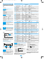
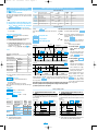
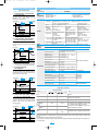
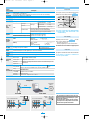
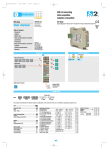
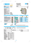
D3ed1 UK - uso
22-04-2003
12:59
Pagina 3
DIN-rail mounting
double action controller
with analogue output
E
S
E
R
I
E
c
D3 line
ASCON spa
D3 line
User manual
ISO 9 0 0 1
certified
User Manual • M.I.U. D3-3/03.04 • Cod. J30-478-1AD3 EF
Table of contents
- Resources
- Model code
- Description and table of standard
parameters
- Description and table of special
function parameters
- Technical specifications
ASCON spa
20021 Bollate
(Milan) Italy
Tel. +39 02 333 371
Fax +39 02 350 4243
http://www.ascon.it
e-mail [email protected]
Operating mode
Resources
Control
D3
Retransmission
Alarms
Main universal input
PV/SP
PV
12
OP1
1
OP1
OP2 OP3 OP5
OP4
OP1 OP2 OP3 OP5
3
OP5
OP1 OP2 OP3
4
OP1 OP2
OP3 OP5
5
OP1 OP4
OP2 OP3 OP5
6
OP4 OP2 OP1
2
OP2
Digital input (option)
IL
OP3
OP4
7
Special function Digital input IL function
(option)
Single
action
Double
action
OP1 OP5
OP3 OP5
OP2 OP3
OP5
8
OP5 OP2 OP1
(option)
9
OP5 OP4 OP1 OP2 OP3
10
Setpoint
S
Modbus RS485
Parameterisation
Supervision
Valve
OP1 OP2
OP3
OP3 OP5
Fuzzy tuning with automatic selection
One shot
One shot
Natural frequency
Auto tuning
Model code
Configuration
I L M N - O P Q R
Mod.
D 3
Line
1st part
2nd part
The product code indicates the specific hardware coniguration of
Serial communications
the instrument, that can be modified by specialized engineers only
5 B C D - E F 0 0 /
Basic
Accessories
D 3
Line
B
1
5
Ouput OP1-OP2
Relay - Relay
SSR - SSR
Input type and range
TR Pt100 IEC751
TR Pt100 IEC751
TC L Fe-Const DIN43710
TC J Fe-Cu45% Ni IEC584
TC T Cu-CuNi
TC K Cromel-Alumel IEC584
TC S Pt10%Rh-Pt IEC584
TC R Pt13%Rh-Pt IEC584
TC B Pt30%Rh Pt6%Rh IEC584
TC N Nicrosil-Nisil IEC584
TC E Ni10%Cr-CuNi IEC584
TC NI-NiMo18%
TC W3%Re-W25%Re
TC W5%Re-W26%Re
Dc input 0…50mV
Dc input 10…50mV
Custom input range
-99.9…300.0 °C
-200…600 °C
0…600 °C
0…600 °C
-200 …400 °C
0…1200 °C
0…1600 °C
0…1600 °C
0…1800 °C
0…1200 °C
0…600 °C
0…1100 °C
0…2000 °C
0…2000 °C
Engineering units
Engineering units
C
Special function
CanBus
RS485 Modbus/Jbus SLAVE
3
5
Not fitted
Start-up + Timer
Options
None
Valve drive output
Analogue output
Valve drive output + Analogue output (retr.)
D
0
2
5
7
User manual
-99.9…572.0 °F
-328…1112 °F
32…1112 °F
32…1112 °F
-328…752 °F
32…2192 °F
32…2912 °F
32…2912 °F
32…3272 °F
32…2192 °F
32…1112 °F
32…2012 °F
32…3632 °F
32…3632 °F
I
0
0
0
0
0
0
0
0
0
0
1
1
1
1
1
1
1
L
0
1
2
3
4
5
6
7
8
9
0
1
2
3
4
5
6
F
0
1
2
3
Italian/English (std)
French/English
German/English
Spanish/English
N
Alarm 1 type and
AL..
function
Disabled or used by Timer
(only for AL3)
Sensor break
/ LBA
active high
Absolute
active low
active high
Deviation
active low
active out
Band
active in
1
2
3
4
5
6
7
1
2
3
4
5
6
7
0
1
2
3
4
5
6
Setpoint type
Local only
Local and 2 tracking stored Setpoint
Local and 2 Stand-by stored Setpoint
R
0
1
2
Control mode
ON-OFF reverse action
ON-OFF direct action
P.I.D. single reverse action
P.I.D. single direct action
Linear cool output
P.I.D.
ON-OFF cool output
double action Water cool output
Oil cool output
M
0
1
2
3
4
5
6
7
Output configuration
Single Action Double action
Relay
Heat Relay, Cool Relay
SSR drive
Heat Relay, Cool SSR Drive
Analogue
Heat SSR Drive, Cool Relay
Heat Relay, Cool Analogue
Heat Analogue, Cool Relay
Valve drive
Heat SSR Drive, Cool Analogue
Heat Analogue, Cool SSR Drive
1
E
0
2
O P Q
1 2 3
0 0 0
1
2
3
4
5
6
7
D3ed1 UK - uso
22-04-2003
12:59
Pagina 4
Standard parameters description
The parameters shown in the table are divided
into groups which work in the same way. Below
they will be described as they are listed in the
table.
Configuration
Digital input function - Table 1
Parameter description
Not used
PV measure hold
Auto/Man
1st stored Setpoint
2st stored Setpoint
Run Timer
IL
unit
Engineering units - Table 2
Parameter descr.
Parameter descr.
A (Ampere)
°C (degree Centigrade)
bar
°F (degree Fahrenheit)
- ( none)
psi
Rh
mV (millivolt)
pH
V (Volt)
mA (milliampere)
Table of standard parameters
Configuration
Mnemonic
code
IL
Unit
Sc.dd
Sc.Lo
Sc.Hi
Prot
baud
retr
rtH
Parameter description
Digital input function IL
Engineering unit
N° of decimals
Low range
High range
Communications protocol
Baud rate
Output range
Retransmitted signal
Range
Units
see table 1
see table 2
0...3
-999...9999
engineer. units
-999...9999
engineer. units
M.bus/Jbus
1200,2400,4800,9600 baud
0...20/4...20
mA
PV/SP
Factory
setting
not used
none
0
Low range
High range
M.bus
9600
4-20
PV
Notes
linear scale only
minimum range 100 digit
if output OP5 option is present
unless used as a control analogue output
Setpoint
Mnemonic
code
A1S.P
A2S.P
A3S.P
SL. u
SL. d
SP L
SP H
SP 1
SP 2
SP
Parameter description
AL1 alarm threshold
AL2 alarm threshold
AL3 alarm threshold
Setpoint ramp up
Setpoint ramp down
Setpoint low range
Setpoint high range
1st stored Setpoint
2nd stored Setpoint
Setpoint
Range
PV range
PV range
PV range
OFF / 0.1...999.9
OFF / 0.1...999.9
low range...SP H
SP L...high range
PV range
PV range
PV range
Units
engineer. units
engineer. units
engineer. units
digit/min
digit/min
engineer. units
engineer. units
engineer. units
engineer. units
engineer. units
Factory
setting
Notes
It is not enabled if the controller has been
0
configured with alarm n° 2 not active or of
0
sensor break type
0
inhibited With OFF the new Setpoint is reached
inhibited immediately after being entered.
low range
high range
----------
Control mode
Setpoint (SP)
AL1 - AL2 - AL3 threshold
Alarm occurrences of OP1,OP2 and
OP3 outputs, respectively linked to
A3S.P
AL1, AL2 and AL3.
The range of the alarm threshold correspond to the
whole span and it is not limited by the SP Setpoint
span.
A1S.P
A2S.P
SL. u
rump up
SL. d
rump down
Setpoint ramp up- Setpoint ramp down
This parameter specifies the maximum
rate of change of the SP in digit/min.
The SP value is reached according to
the configured rate of change. The new
SP value is called "Target SP" (available via serial communications).
Mnemonic
code
hy.
tune
P.b.
t.i.
t.d.
O.C.
M.res
d.err
t.c.
OP. H
S.Out
MV.tM
MV.hy
dbnd
r.C.G.a
hy. C
Example:
350°
Target Setpoint
350°
Setpoint
change
250°
SL. u
10 digit/minutes
Initial
Setpoint
0
t = 10
When the parameter is OFF, this function is disabled and the new Setpoint is reached immediately after being entered.
Setpoint low limit and Sepoint high limit
Low / high limit of the Setpoint value.
t.c. C
OP. HC
A.Man
Parameter description
Control output hysteresis
Tune run/stop
Proportional band
Integral time
Derivative time
Overshoot control
Manual reset
Error dead band
Cycle time
Control output high limit
Output safety value
Motor travel time
Minimum output step
Dead band
Cool relative gain
Cool output hysteresis
Cool cycle time
Cool control output high limit
Auto/man selection
Units
% range
Start/stop
0.5...999.9
% range
OFF / 0.1...100.0 min
OFF / 0.01...10.00 min
0.01...1.00
0.0...100.0
% output
OFF / 0.01...10.0 digit
sec
1...200
% output
10.0...100.0
% output
0.0...100.0
15...600
sec
0.1...5.0
% output
% output
-10.0...10.0
0.1...10.0
0.1...10.0
1...200
10.0...100.0
Auto/Man
Low limit
SP. H High limit
SP. L
Setpoint range
Algorithm
Type
On - Off
Setting 1 is disabled
Without integral time
PID
Time proportional only
-100.0...+100.0 Heat/Cool
Valve
drive
On/Off only
Time proportional only
PID only
Heat
Cool
Range
Units
% range
0.1...10.0
none / Ltch / Bloc / LtbL
OFF / 1...9999
sec
OFF / 0.1...100.0 % ouput
1...9999
sec
OFF / 1...30
sec
OFF / -60...+60
digit
1...247
engineer. units
PV range
PV range
engineer. units
Factory
setting
0.5
none
inhibited
0.5
1
inhibited
inhibited
247
-------
Notes
The same parameters are available for AL2
and AL3 alarms
OFF = sensor break
t.mod = OFF only
Only if sT.OP different than OFF
If OP5 output is present and not configured as control output
B - Natural frequncy
tune
Automatic tune
The Fuzzy-Tuning determines automatically the best PID
term with respect to the process behaviour.
The controller provides 2 types of “one shot” tuning algorithm, that are selected automatically according to the
process conditions when the operation is started
Setpoint change
Tuning start
End of the tuning
operating and setting
of the new calculated terms
Control output
A - STEP respose
SP
1st stored SP - 2nd stored SP
Values of the two Setpoints, that are
SP. 2
activated by mean of digital input or
communications parameters. If configured with
“Tracking”, the previous Local Setpoint value will be
lost, when the stored Setpoint is selected.
If configured with “Stand-by” the Local Setpoint
value will not be lost, when the Stand-by Setpoint is
selected. It will operate again when back to Local.
0.5
20
100.0
Auto
Notes
Alarm and auxiliary
Mnemonic
Parameter description
code
AL1 hysteresis
A1hy
Latch.and blocking alarm functions
A1Lb
LBA delay
t.Lba
Soft-start output value
St.OP
Soft-start activation time
St.tn
Filter time costant
t.Fil
Input shift
In.Sh
Communications address
Addr
Retransmission low range
rt.lo
Retransmission high range
rt.hi
Setpoint change
SP. 1
5.0
5.0
1.00
1.00
5.0
inhibited
20
100.0
0
60
0.5
0.5
1
% range
sec
% ouput
Control mode
Instrument range
Factory
setting
0.5
Range
0.1...10.00
PV variable
End of the tuning
operating and setting
of the new calculated terms
Tuning start
This type is selected when the PV is close to the SP
Setpoint.
This method has the advantage of a better accuracy in the
term calculation with a reasonable speed calculation.
Control output
This type is selected when, at the start of the autotune
operation, the PV is far from the Setpoint of more than
5% of the span. This method has the big advantage of fast calculation, with a reasonable accuracy in the term calculation.
2
The Fuzzy Tuning determines automatically the best
method to use to calculate the PID term, according the
process conditions.
D3ed1 UK - uso
22-04-2003
12:59
Pagina 5
Standard parameters description - follows
Control mode - follows
Heat/Cool control
p.B.
Proportional band
This parameter specifies the proportional band coefficient that multiplies the error (SP - PV)
t.i.
Integral time
It’s the integral time value, that specifies the time
required by the integral term to generate an output
equivalent to the proportional term. When Off the integral
term is not included in the control algorithm.
By a sole PID control algorithm, the controller handles two different outputs, one of these performs the Heat action, the
other one the Cool action. It is possible to overlap the outputs.
A - Heat/Cool actions separated
d.bnd positive 0...10.0%
100%
O.C.
Overshooot control
This parameter specifies the span of action of the overshoot
control. Setting lower values (1.00 —> 0.01) the overshoot
generated by a Setpoint change is reduced. The overshoot
control doesn’t affect the effectiveness of the PID algorithm.
Setting 1, the overshoot control is disabled.
0%
OP. H
control output
OP.HC
cool output
Control output high limit
It specifies the maximum value the control
output can be set.
Separate parameters for both heat and cool
outputs limitation are available.
-100%
0%
Heat
output
r.Cga
Relative cool gain
It permits to adjust the proportional cool action.
100%
50%
In.Sh
Input shift
This value is added to the measured PV input value. Its effect
is to shift the whole PV scale of up to ± 60 digits.
Addr
Controller address
The address range is from 1 to 247 and must be unique for
each controller on the communications bus to the supervisor.
Heat
output
0%
0%
PID output
On
Cool
output
100%
50%
Off
0%
PID
output
d.bnd
Alarm occurances of OP1 - OP2 - OP3 outputs, respectively linked to AL1 - AL2 - AL3
The relay/SSR output OP1, OP2 and OP3, can be used as alarm outputs only if they are not used as control outputs.
For each alarm is possible to configure:
A - The type and the operationg condition of the alarm
B - The functionality of the alarm acknowledgement
C - The blocking function on start-up
D - Loop break or sensor break
A- Alarm type and function
Band alarm
Deviation alarm
Absolute alarm
On
Off
Active
low
hy
high range
low range
On Active
Off high
SP
On
Off
Active
low
SP
On Active
Off out
On
Off
hy
- low range
+ high range
alarm threshold
low range
Active
in
hy
hy
alarm threshold
high range
B/C- Latching and blocking enable
AL1, AL2, AL3
latching and blocking
For each alarm it is posA3L.b
sible to select the following functions:
A1L.b
A2L.b
None
latching
blocking
both latching and blocking
Auxiliary
hy. C
100%
Cool
output
alarm threshold
d.bnd
Dead band
It is the zone where it is possible to separate or overlap
the heat and cool actions.
0%
PID output
50%
d.bnd
On Active
Off high
MV.hy
Minimum step
It specifies the minimum allowed time of activation of
the output to a valve that produces a sensible effect. It is
related to the deadband of the valve
100%
OP. HC
OP. H
Output safety value
Output Value in case of input anomaly.
Travel time
It provides the time required to the valve to go from the
0% position to 100%
Cool
output
D - On-Off Cool action
100%
S.Out
MV.tM
Heat
output
0%
0%
PID output
50%
B - Heat/Cool actions overlapped
d.bnd negative -10.0....0%
d.err
Error Dead Band
Inside this band for (PV - SP), the control output does
not change to protect the actuator
(output Stand-by)
t.c. C
cool output
d.bnd
Cool
output
100%
Manual reset
This specifies the control output value when PV = SP, in
a PD only algorithm (lack of the integral term).
Control output cycle time
It’s the cycle time of the time proportioning
control output. The PID control output is
provided by the pulse width modulation of
the waveform.
100%
d.bnd
Heat
output
M.res
t.c.
control output
=2.0 r.Cga 0.1…10.0
=1.0
-100%
=0.5
-100%
OP. HC
OP. H
t.d.
Derivative time
It is the time required by the proportional term P to repeat
the output provided by the derivative term D. When Off the
derivative term is not included in the control algorithm.
C - Cool action adjusting
Example with different relative cool gains
Alarm acknowledge function
The alarm, once occurred, is maintained
until to the time of acknowledgement. The
acknowledge operation is performed by
serial communications.
After this operation, the alarm leaves
the alarm state only when the alarm
condition is no longer present.
Start-up disabling
Ramp down
Disable
∆SP
SP
On
Off
Start-up
Ramp up
SP
∆SP
Disable
On
Off
D- “Loop Break Alarm” LBA or sensor break
Setting a value between 1 and 9999 sec
t.Lba
LBA delay
the alarm works as LBA+Sensor
Setting “none”
the alarm works as Sensor break with break with delay.
immediate action.
Start-up
∆SP Threshold = SP±range
When the cause of the alarm disappears, the alarm status stops.
Soft-start control output function
OP5 Retransmission output (if option installed)
When OP5 output
is present and not
configured as control output, it
retransmits
linearised PV or SP.
With rt.Lo greater
than rt.Hi it is possible to obtain a
reverse scale.
20
mA
St.OP
Soft-Start value
Value of the control output during the
Soft-start activation time.
retr = 4-20
rtH = P.V.
rt.Lo = 800
rt.Hi = 1200
4
Soft-Start activation
time
Time duration (starting from the
power on) of the Soft-start function.
100%
63,2%
°C
0
Soft-start
0%
St.tM
Power-on
3
PV
St.OP
St.TM
800 1200 1600
Input digital filter
100%
OP
Time
t.Fil
Time
Time constant, in sec, of the RC input filter applied to the PV input.
When this parameter is set to
“inhibited” the filter is bypassed.
D3ed1 UK - uso
22-04-2003
12:59
Pagina 6
Special parameters description
Table of special function parameters - (if option installed)
In order to have the above functions the product code
digit emust be 2
For example: mod. D3 3100-2000
To improve the instrument performances and to reduce
the wiring and installation costs, two special functions
are available:
- Start-up
- Timer
A This functions is disable with Heat/Cool control.
Selecting Timer or Start-up, the Soft-start function is disabled, therefore the parameters
St.TM
St.OP
will not be enabled .
1 To select these two functions to use set the parameter as in table 1:
Timer/Start-Up operating mode
This parameter defines (see table 3):
t.Mod
- When the count starts.
- The state of the control output at the end of the count
2 To select the Start-up function select 1
3 To select the Timer function select the value from 2
to 6 and use alarm AL3 (output OP3) configured with
configuration code q= 0.
Example: conf. i l m n-o p 0 r
Timer and Start-Up
Mnemonic
code
t.Mod
t.Act
time
S.P.Sb
t.h.SU
S.P.SU
Unit
see table 3
see table 4
sec/min
1...9999
SP L...SP H
0...500
min
SP L...SP H
Timer action
Timer setting
Standy-By Setpoint
Start-Up hold time
Start-Up Setpoint
5.0...100.0
Control output high limit
OP.HS
Factory
setting
0
0
0.5
0
1
0
Parameter description
Range
Timer/Start-up operation mode
The Start-up function includes three phases:
1a “Limy” - The control output is limited to the OP.HS
to 1
Setting
t.Mod
Three parameters are associated to the Start-up function:
2a “Hold” - The process variable is maintained to the
Start-up Setpoint for the time fixed by the
parameter t.h.S.U
t.h.S.U
Start-Up hold time
S.P.S.U
Start-Up Setpoint
OP.HS
Control output high limit
3rd “Off” - When the t.h.S.U time is elapsed the
process variable is maintained to the working Setpoint.
noise
power-on
th.SU
Output to 0
0
Setpoint SP
Output to 0
6
When launched
stand-by Setpoint
Output to 0
7
th.SU
1 digit
SP.SU
40 digit
OP= OP.HS
1
When launched
Control disabled
For t.Mod = 7
100.0
output %
PV
2
3
4
5
tMode ≠ to 1
Start-Up function
Table 3
Timer/Start-up counting mode
Disabled
Start-up function
Counting start time End mode
Control mode
When inside the band
Output to 0
Control mode
When lauched
Output to 0
Notes
with TC = 25%
1sec min.
a
1 “Limy” 2a “Hold”
3a “Off”
1a “Limy” 2a “Hold”
3a “Off”
SP.SU
power-on
noise
1 digit
PV
Setpoint SP
40 digit
OP= OP.HS
There are two possibilities:
A - Start-Up Setpoint SP.SU
lower thant the local
Setpoint
The “Hold” phase starts when
the process variable PV achieves the SP.SU (with a tolerance of 1 digit).
B - Start-Up Setpoint SP.SU ≥
greater or equal to the local
Setpoint
When the process variable PV
achieves the local Setpoint
(with a tolerance of 1 digit),
the Start-up function passes
directly to the “Off” phase.
with TC = 25%
1sec min.
If, at the controller power-on, the
process variable PV is greater
than the lowest between the
Whether the process variable, for any reason (e.g. load change), decreases at a
SP.SU
and the working
OP.HS
value lower than (
- 40 digits), the Start-up function starts again from
Setpoint , the next phase (“Hold”
the “Limy” phase.
or “Off”) will be executed instead
When the Start-up is in Hold phase, if the local Setpoint becomes lower than
of the “Limy” phase.
the Start-up Setpoint or if the operating mode changes to manual, the Startup function passes to the “Off” phase.
a
3a “Off”
1 “Limy”
4 If Timer function is selected it will show the parameter above:
t.Act
Timer action
By this parameter can be defined:(see table 4)
- the time units
- the starting mode
- the OP3 status when the timer is running.
When the timer is not running, the OP3 takes the opposite status
1a “Limy”
3a “Off”
Timer setting
time
S.P.SB
(only for
Timer counting modes
Timer (1…9999 sec/min.)
Stand-by Setpoint
t.Mod
= 7)( SP L … SP H )
Table 4
Time units
Seconds
Minutes
Starting mode
Manual by serial
communications
Automatic
at the power on [2]
Manual by serial
communications
Automatic
at the power on [2]
A - Counting start time inside the band, end in control
mode.
B - Counting start time inside the band, end with control output forced to zero.
The time counting starts only when the error is inside a
± 1 digit band. The control action is not affected by the
Timer function.
The time counting starts only when the error is inside a
± 1 digit band. At the end, the control output is forced to
zero. [1]
Timer launch
OP3
status [1]
Value
Off
On
Off
On
Off
On
Off
On
0
1
2
3
4
5
6
7
time
t.Mod
=2
Timer launch
time
t.Mod
=3
Setpoint
Setpoint
±1 digit
band
Process
variable PV
Process
variable PV
±1 digit
band
Output OP
Output OP
AL3
AL3
[1] If used by Timer
[1] When the Timer is not running the control output is
forced to zero, also before the Timer launch.
[2] Using this selection, manual
starting mode is possible too
4
D3ed1 UK - uso
22-04-2003
12:59
Pagina 1
Technical specifications
Special function parameters description
Timer function mode
Features
(at 25°C T. envir. temp)
C - Counting start time = timer launch time,
end in control mode.
The time counting starts when the timer is
launched. The control action is not
affected by the Timer function.
By means of the confiurguration tools is possible to choose:
Total
- the type of input
- the type and functionality of the alarms
configurability - the type of control input
- the type of Setpoint
- the type of output
- control parameter values
time
A/D converter with resolution of 50.000 points; Update measurement time: 0.2 sec;
Sampling time: 0.5 sec; Input bias: - 60…+ 60 digit; input filter: 1…30 sec. OFF = 0
Common
characteristics
=4
t.Mod
Timer launch
Description
Setpoint
0,25% ± 1 digit (per termoelementi)
0,1% ± 1 digit (per mA e mV)
2 or 3 wires
Resistance
Pt100Ω a 0°C
connection
thermometer
(IEC
751)
Burnout
(for ∆T: R1+R2
°C/°F
selectable
(with any combination)
must be < 320 Ω)
Accuracy
Process
variable PV
Output OP
PV Input
L,J,T,K,S, R, B, N, E,W3,W5
(IEC 584)
Rj >10MΩ
°C/°F selectable
Thermocouple
AL3
D - Counting start time = timer launch time,
end with control output forced to zero.
4…20mA,0-20mA
DC input (current) with external shunt 2.5Ω
Rj >10MΩ
The time counting starts when the timer is
launched. At the end, the control output is forced to
zero. [1]
0-50mV
DC input (voltage) 10…50mV,
Rj >10MΩ
The closure of the external contact produces
any of the following actions
Timer launch
time
=5
t.Mod
Digital
input
Mode of
operation
Process
variable PV
Output OP
AL3
Control mode
The time counting starts when the timer is
launched and the control output is forced to zero. At
the end, the control action starts.
Burnout. Engineering units
Conf. decimal point position Input drift:
Init. Scale -999…9999
<0.1% / 20°C Env. Temp.
Full Scale -999…9999
<5µV / 10Ω Wire Res.
(min. range of 100 digits)
Auto/Man mode change, Stored Setpoints activation,
measure hold . Timer activation (if options installed)
PID with overshoot control or On-off - PID with valve drive algorithm,
for controlling motorised positioners
Proportional band (P)
0.5...999.9%
Integral time (I)
01...100.0 min
Derivative time (D)
0.01...10.00 min
Error dead band
0.1...10.0 digit
Overshoot control
0.01...1.0
Manual reset
0.0...100.0%
OFF = 0
Single action PID algorithm
Control output high limit
10.0...100%
Soft-start output value
0.1...100.0%
Output safety value
0.0...100.0% (-100.0...100.0% for Heat / Cool)
OFF = 0
On-Off algorithm
Control output hysteresis
0.1...10.0%
Dead band
-10.0...10.0%
Relative cool gain
0.1...10.0
Double action
PID algorithm
(Heat / Cool)
with overlap
Cycle time (Time proportional only) 1...200 sec
Timer launch
time
=6
t.Mod
Line: 150Ω max
Input drift:
<2µV/°C.Env. Temp
<5µV / 10Ω Wire Res.
Cycle time (Time proportional only) 1...200 sec
[1] When the Timer is not running the control output
is forced to zero, also before the Timer launch.
E - No control action during
the counting time.
Max. wire Res:
20Ω max (3 wires)
Sensitivity: 0.35°C/10° E. T.
<0.35°C / 10Ω Wire Res.
1 single or double action P.I.D. loop or ON/OFF with 1, 2 or 3 alarms
Algorithm
Setpoint
Internal cold junction
compensation con NTC
Error 1°C/20°C ±0.5°C
Burnout
Between 100…240V~
the error is minumal
Setpoint
Process
variable PV
Control output high limit
10.0...100.0%
Cool output hysteresis
0.1...10.0%
Motor travel time
15...600 sec
Motor minimum step
da 0.1...5.0%
Valve drive PID algorithm without
feedback potentiometer
Output OP
Digital input commands
F - Control action with stand-by Setpoint
during the counting time
The time counting starts when the timer is
launched and the control action use the Stand-by
Setpoint. At the end, the control action use the
working Setpoint.
Timer launch
=7
t.Mod
time
Performed operation
Off
Function
None
—
—
PV measure hold
Normal operation
PV is hold
Set manual mode
Automatic
Manual
1st stored
Setpoint
Local
1st SP
2nd stored
Setpoint
Local
2nd SP
—
Timer
start
Standard
Setpoint
AL3
On
Notes
Not used
The value of PV is “frozen” at the time the digital
input goes to the close state
The permanent closure forces the chosen stored
value. Setpoint modification is not possible.
The impulsive closure, selects the stored value.
Setpoint modification is allowed.
Setpoint
Process
variable PV
Timer
S.P. 2
Output OP
AL3
The impulsive closure is enough to start the Timer
A function is assigned, through the configuration procedure to digital input.
The configured function is activated when the digital input (free voltage contact or open collector output) is in the On state
(closed).
It is deactivated by setting the input to the Off state (open).
The activation of the function through the digital input has the highest priority than through the keypad or through the serial communications.
5
D3ed1 UK - uso
22-04-2003
12:59
Pagina 2
Technical specifications
Commands
Auto/Manual
Features
Description
(at 25°C T. envir. temp)
OP1-OP2
SPST Relay N.O., 2A/250V~ for resistive load
outputs
SSR, 1A/250V~ for resistive load
Too meet the double isolation requirements OP1 and OP2 must have the same load voltage
OP3 output
SPST Relay N.O. 2A/150V~ for resistive load
OP4 output
The bumpless action is present switching between AUTO,
MAN and vice versa with the parameter A.Man .
Logic not isolated: 0/5V-, ±10% 30 mA max
OP5 output (opt.) Control or PV/SP retr.; Galvanic isolation: 500 V~/1 min; Res. 12bit (0.025%); Accuracy 0.1%; 4/20 mA 750 Ω 15 V max
Hysteresys 0.1...10.%
Active high
Action type
AL1 - AL2 AL3
Alarms
Active low
Action
AUTO
100%
Setpoint SP
SP (PV)
± range
Band threshold
0...range
Absolute threshold
whole range
SP
Op.r
PV
0
100%output OP
Deviation threshold
AUTO
MAN
SP = PV
OPMAN=OPAUTO
OP setting
Y
OP
OP
OPAUTO=OPMAN
0
Sensor break, Heater break and Loop break detection
Special functions
A In case of power failure, the AUTO/MAN status
Acknowledge (latching), activation inhibit (blocking)
and the output value remain stored in the
controller memory
Connected to Timer or program (if options installed)
Up and down ramps 0.1…999.9 digit/min. (OFF=0)
Low limit: from low range to high limit
Local plus 2 stored with tracking or Stand-by High limit: from low limit to high range
Local
Setpoint
Timer starting
Automatic start at the power on, Digital inputs or serial comm.s
Setting time:
1…9999 sec/min
Stand-by Setpoint:
SC.LO <= SP >= SL.HI
Timer
Special
functions
(option)
Start-up Setpoint:
Hold time :
Control output high limit:
Start-up
SC.LO <= SP >= SL.HI
0...500 min
5.0...100.0%
The Timer function can be started or stopped any time.
One shot Auto tuning
Fuzzy-Tuning
one shot
The controller selects automatically the best method
according to the process conditions
Auto/Man
station
Standard with bumpless function, digital input or serial communications
One shot Natural frequency
Output lock
Serial comm.s RS485 isolated, Modbus/Jbus protocol, 1200, 2400, 4800, 9600 bit/sec, 3 wires
Auxiliary
+24V– ± 20% 30mA max - for external transmitter supply
Supply
Detection of out of range, short circuit or sensor break with automatic activation of the
Measure input
safety strategies and alerts on display
Operational
Safety
Control output
Safety value: -100%…100%
Parameters
Parameter and configuration data are stored in a non volatile memory for an
unlimited time
Outputs lock
t.Act
Depending on the Timer action
selection,
there can be two different starting ways:
- Automatic at the power on
- Manual by digital inputs or serial communications.
Power supply
24V~ (-15% +25%) 50/60Hz e 24V-(dc voltage) (-15% +25%)
(PTC protected)
The outputs are switched to the OFF via serial communications.
A The
outputs lock/unlock is maintained in
case of power failure.
Power consumption
3W max
EN61010-1 (IEC1010-1). installation class 2 (2500V), pollution class 2,
instrument class II
Safety
General
characteristics Electromagnetic
compatibility
Protection
Dimensions
Compliance to the CE standards
Terminal strip IP20
Pitch: 22.5 mm - depth: 114.5 mm - with: 53
Serial communications connection example
Configuration
D3
1
5
2
6
3
7
Configuration
Cd-Rom
4
8
RS485
D3
9 10 11 12
13 14 15 16
For SCADA
OP30
operator
panel
PC with
Autolink
D3 - 31 max instruments
D3 - 31 max instruments
1
5
2
6
3
7
4
8
D3
9 10 11 12
13 14 15 16
1
5
2
6
3
7
4
8
D3
9 10 11 12
13 14 15 16
1
5
D3
2
6
3
7
4
8
1
5
2
6
3
7
4
8
D3
9 10 11 12
9 10 11 12
13 14 15 16 13 14 15 16
1
5
2
6
3
7
4
8
D3
9 10 11 12
13 14 15 16
Warranty
Local control
RS485
1
5
2
6
3
7
4
8
D3
9 10 11 12
13 14 15 16
1
5
2
6
3
7
4
8
D3
9 10 11 12
13 14 15 16
1
5
D3
2
6
3
7
4
8
1
5
2
6
3
7
COM
OP30
OPR PAR ALM
1
5
4
8
2
6
3
7
4
8
D3
D3
9 10 11 12
9 10 11 12
13 14 15 16 13 14 15 16
9 10 11 12
13 14 15 16
6
ALM
RS485
We warrant that the products will be free from
defects in material and workmanship for 3 years
from the date of delivery.
The warranty above shall not apply for any failure
caused by the use of the product not in line with
the instructions reported on this manual.