1
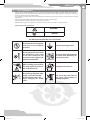
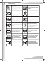
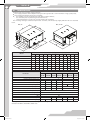
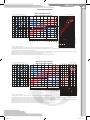
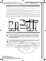
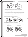
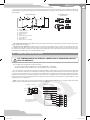
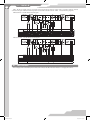
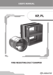
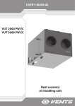
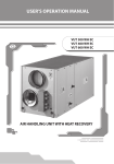
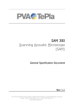
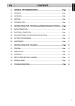
USER’S MANUAL MPA ... W MPA ... W LCD Single-block air supply unit with water heater V38EN-02.indd 1 29.07.2015 16:03:42 2 CONTENTS Safety requirements ............................................................................................... Introduction .............................................................................................................. Purpose ....................................................................................................................... Delivery set ................................................................................................................ Designation key ....................................................................................................... Technical data ........................................................................................................... Unit design and operating logic ........................................................................ Mounting and set-up ............................................................................................. Connection to power mains ................................................................................ Unit control ............................................................................................................... Technical maintenance ......................................................................................... Troubleshooting ...................................................................................................... Storage and transportation regulations ......................................................... Manufacturer's warranty ...................................................................................... 3 5 5 5 5 6 9 9 11 12 13 13 14 15 Acceptance certificate ........................................................................................... 15 Installation certificate ............................................................................................ 15 Seller information ................................................................................................... 15 V38EN-02.indd 2 29.07.2015 16:03:42 3 SAFETY REQUIREMENTS • Read the user’s manual carefully prior to the operation and installation of the MPA…W / MPA... W LCD air supply unit. • Fulfil the operation manual requirements as well as the provisions of all the applicable local and national construction, electrical and technical codes and standards. • The warnings contained in the user’s manual must be considered most seriously since they contain vital personal safety information. • Failure to follow the safety requirements may result in an injury or unit damage. • Read the manual carefully and keep it as long as you use the unit. • While transferring the unit control the user’s manual must be turned over to the receiving operator. Symbol legend used in the manual: WARNING! DO NOT! UNIT MOUNTING AND OPERATION SAFETY PRECAUTIONS V38EN-02.indd 3 Disconnect the unit from power mains prior to any installation operations. The unit must be grounded! Do not operate the unit outside the temperature range stated in the user’s manual. Do not operate the unit in aggressive or explosive environments. Do not use damaged equipment or cables when connecting the unit to power mains. While installing the unit follow the safety regulations specific to the use of electric tools. Unpack the unit with care. Do not change the power cable length at your own discretion. Do not bend the power cable. Avoid damaging the power cable. Do not lay the power cable of the unit in close proximity to heating equipment. 29.07.2015 16:03:43 4 Do not touch the unit controls with wet hands. Do not carry out the installation and maintenance operations with wet hands. Use the unit only for its intended purpose. Do not wash the unit with water. Protect the electric parts of the unit against ingress of water. Do not put any water containers on the unit, i.e. flower vases. Do not store any explosive or highly flammable substances in close proximity to the unit. V38EN-02.indd 4 ON OFF Disconnect the unit from power mains prior to any technical maintenance. Do not allow children to operate the unit. Avoid damaging the power cable. Do not put any foreign objects on the power cable. Do not sit on the unit and do not put other objects on it. Do not open the unit during operation. When the unit generates unusual sounds, odour or emits smoke disconnect it from power supply and contact the Seller. In case of continuous operation of the unit periodically check the security of mounting. Do not block the air duct when the unit is switched on. Do not direct the air flow produced by the unit towards open flame or ignition sources. 29.07.2015 16:03:45 5 INTRODUCTION The user’s manual consisting of the technical details, operating instructions and technical specification applies to the installation and mounting of the MPA…W / MPA... W LCD air supply unit (hereinafter referred to as «the unit»). PURPOSE The air supply unit is intended for supplying pre-heated outdoor air and cleaning it of any flammable or explosive substances, chemically active vapours, dust, soot etc. To ensure the necessary air quality the unit must be mounted in an enclosed dry space with ambient temperatures from +1 °С to +40°С. The air supply unit is integrated into an air distribution system by connecting to rectangular air ducts. Alternatively it may be connected to round ductwork by means of the appropriate duct fittings available as special accessories. The air supply unit is a component and, therefore, may not be commissioned for standalone operation. THE UNIT IS NOT INTENDED TO BE USED BY CHILDREN, PHYSICALLY OR MENTALLY DISABLED PERSONS, PERSONS WITH SENSORY DISORDER, PERSONS WITH NO APPROPRIATE QUALIFICATION. ALL OPERATIONS WITH THE UNIT MUST BE PERFORMED ONLY BY PROPERLY QUALIFIED PERSONNEL AFTER THE APPROPRIATE SAFETY BRIEFING. THE UNIT INSTALLATION SITES MUST PREVENT ACCESS BY UNATTENDED CHILDREN. DELIVERY SET Air supply unit User's manual Instruction manual for the air supply unit control system (MPA ... W LCD) Packaging 1 item 1 item 1 item 1 item DESIGNATION KEY Unit type MPA − single-block air supply unit MPA X W LCD Maximum air capacity, [m3/h] 800, 1200, 1800, 2500, 3200, 3500, 5000 Water heater availability W - water type Control unit availability V38EN-02.indd 5 29.07.2015 16:03:45 6 TECHNICAL DATA Hazardous parts access and water ingress protection: the air supply unit utilises IP 44 compliant motors (protection against bodies 1.0 mm in diameter or larger; splash-proof ); the air supply unit installed in ducts is IP 22 compliant: • the assembly is protected against bodies larger than 12.5 mm in diameter; • the conductive parts are protected against accidental touch; • water drops falling at an angle up to 15° remain harmless the equipment. The unit design undergoes continuous improvement - therefore, some models may slightly differ from the ones described herein. MPA ... W MPA ... W LCD Overall and mounting dimensions, [mm] Model B B1 B2 B3 B4 H H1 H2 L L1 L2 K MPA 800 W / MPA 800 W LCD 400 420 549 500 674 200 220 352 650 530 - G ¾" MPA 1200 W / MPA 1200 W LCD 400 420 549 500 674 200 220 352 650 530 - G ¾" MPA 1800 W / MPA 1800 W LCD 500 520 649 600 775 250 270 480 800 680 - G ¾" MPA 2500 W / MPA 2500 W LCD 500 520 649 600 775 300 320 480 800 680 - G ¾" MPA 3200 W / MPA 3200 W LCD 600 620 759 710 1000 300 320 530 1000 880 440 G ¾" MPA 3500 W / MPA 3500 W LCD 600 620 759 710 1000 350 370 530 1000 880 440 G ¾" MPA 5000 W / MPA 5000 W LCD 800 820 971 925 1212 500 520 670 1299 720 360 G 1" Main technical data Parameter MPA 800 W MPA 1200 W Supply voltage, V / 50 Hz MPA 1800 W MPA 2500 W 1~230 Number of water heating coils 0,245 0,41 0,49 Total unit current, [A] 1,08 1,8 2,15 2,84 750 1200 1870 2150 Rotation speed, [min-1] 1650 1850 1100 1000 35 38 40 45 Maximum transported air temperature, [°С] 3~400 1,270 1,8 2,3 4,5 3000 3250 1200 6500 1400 53 from -40 to +45 Casing material Aluzinc Insulation 25 mm, mineral wool Filter Weight, [kg] MPA 5000 W 3~400Y 0,65 Max. air capacity, [m3/h] Connected air duct size, [mm] MPA 3500 W 4 Total unit power, [kW] Sound pressure at 3 m, [dB(A)] MPA 3200 W G4 400x200 42 (45) 43 (46) 500x250 500x300 600x300 600x350 800x500 62,5 (62,5) 63 (63) 90 (101) 90 (101) 136 (136) The weight of the MPA... W LCD series units featuring a control unit is given in parentheses while the rest of the parameters are identical for the MPA ... W and MPA ... W LCD series. V38EN-02.indd 6 29.07.2015 16:03:45 7 WATER HEATER DIAGRAMS MPA 800 W / MPA 800 W LCD MPA 1200 W / MPA 1200 W LCD Coil heating capacity, [kW] Outside air temperature, [°C] Air temperature downstream of the water heater, [°C] Water pressure drop, [kPa] Air speed in the coil, [m/s] Air flow in the heating coil, [m3/h] How to use water heater diagrams: Water flow in the coil, [l/s] Air Speed. Starting from 950 m3/h on the air flow scale draw a vertical line (1) till the air speed axis which makes about 3.35 m/s . Supply air temperature. Prolong the line up to the point where it crosses the outside air temperature (blue curve), e.g. -15 °C; then draw a horizontal line from this point to the left till crossing water in/out temperature curve (70/50 °C). From this point draw a vertical line . Heating coil capacity. Prolong the line up to the point where it crosses the outside air temperature -15 °C (red curve) and draw a horizontal line from this point to the right until it crosses water in/out temperature curve (70/50 °C), from here draw a vertical line up to the scale representing the heating coil capacity (16.0 kW). Water flow. Prolong the line down to water flow axis at the bottom of the graphic (0.2 l/s). Water pressure drop. Draw the line from the point where the line crosses the black curve to the pressure drop axis. (2.1 kPa). MPA 1800 W / MPA 1800 W LCD MPA 2500 W / MPA 2500 W LCD Coil heating capacity, [kW] Air speed in the coil, [m/s] Air flow in the heating coil, [m3/h] Water pressure drop, [kPa] Outside air temperature, [°C] Air temperature downstream of the water heater, [°C] How to use water heater diagrams: Water flow in the coil, [l/s] Air Speed. Starting from 1500 m3/h on the air flow scale draw a vertical line till the air speed axis which makes about 3.3 m/s. Supply air temperature. Prolong the line up to the point where it crosses the outside air temperature (blue curve), e.g. -25 °C; then draw a horizontal line from this point to the left till crossing water in/out temperature curve (70/50 °C). From this point draw a vertical line to the supply air temperature axis on top of the graphic (+30 °C). Heating coil capacity. Prolong the line up to the point where it crosses the outside air temperature -25 °C (red curve) and draw a horizontal line from this point to the right until it crosses water in/out temperature curve (70/50 °C), from here draw a vertical line up to the scale representing the heating coil capacity (33.0 kW). Water flow. Prolong the line down to water flow axis at the bottom of the graphic (0.42 l/s). Water pressure drop. Draw the line from the point where the line crosses the black curve to the pressure drop axis. (10.0 kPa). V38EN-02.indd 7 29.07.2015 16:03:45 8 MPA 3200 W / MPA 3200 W LCD MPA 3500 W / MPA 3500 W LCD Coil heating capacity, [kW] Outside air temperature, [°C] Air temperature downstream of the water heater, [°C] Water pressure drop, [kPa] Air speed in the coil, [m/s] Air flow in the heating coil, [m3/h] How to use water heater diagrams: Water flow in the coil, [l/s] Air Speed. Starting from 2400 m3/h on the air flow scale draw a vertical line till the air speed axis which makes about 3.61 m/s. Supply air temperature. Prolong the line up to the point where it crosses the outside air temperature (blue curve), e.g. -20 °C; then draw a horizontal line from this point to the left till crossing water in/out temperature curve (70/50 °C). From this point draw a vertical line to the supply air temperature axis on top of the graphic (+30 °C). Heating coil capacity. Prolong the line up to the point where it crosses the outside air temperature -20 °C (red curve) and draw a horizontal line from this point to the right until it crosses water in/out temperature curve (70/50 °C), from here draw a vertical line up to the scale representing the heating coil capacity (50.0 kW). Water flow. Prolong the line down to water flow axis at the bottom of the graphic (0.62 l/s). Water pressure drop. Draw the line from the point where the line crosses the black curve to the pressure drop axis. (15.0 kPa). MPA 5000 W / MPA 5000 W LCD Coil heating capacity, [kW] Air speed in the coil, [m/s] Air flow in the heating coil, [m3/h] Water pressure drop, [kPa] Outside air temperature, [°C] Air temperature downstream of the water heater, [°C] How to use water heater diagrams: Water flow in the coil, [l/s] Air Speed. Starting from 2400 m3/h on the air flow scale draw a vertical line till the air speed axis which makes about 4.15 m/s. Supply air temperature. Prolong the line up to the point where it crosses the outside air temperature (blue curve), e.g. -25 °C; then draw a horizontal line from this point to the left till crossing water in/out temperature curve (70/50 °C). From this point draw a vertical line to the supply air temperature axis on top of the graphic (+27 °C). Heating coil capacity. Prolong the line up to the point where it crosses the outside air temperature -25 °C (red curve) and draw a horizontal line from this point to the right until it crosses water in/out temperature curve (70/50 °C), from here draw a vertical line up to the scale representing the heating coil capacity (121.0 kW). Water flow. Prolong the line down to water flow axis at the bottom of the graphic (1.52 l/s). Water pressure drop. Draw the line from the point where the line crosses the black curve to the pressure drop axis. (31.0 kPa). V38EN-02.indd 8 29.07.2015 16:03:46 9 DESIGN AND OPERATING LOGIC MPA W / MPA W LCD are the complete air supply units which ensure filtering, pre-heating and supply of fresh outdoor air into the serviced spaces. The units fit rectangular air ducts with nominal size of 400x200, 500x250, 500x300, 600x300, 600x350 and 800x500 mm. The steel casing has a protective aluzinc coating and a 25 mm mineral wool layer for heat and sound insulation. The built-in G4 filter ensures high-quality purification of the supply air. During the winter time and the off-season the supply air is pre-heated by means of a water (glycol) heater. The water heaters are rated for maximum operating pressure of 1.0 MPa (10 bar) and maximum heat medium temperature of +95 °C. The air supply unit features a double-inlet type centrifugal fan with forward bent blades and a built-in protection thermostat which restarts automatically. The electric motor and impeller of the fan undergo two-plane dynamic balancing. The ball bearings of the electric motor are completely maintenance-free with a minimum service life of 40,000 hours. MPA ... W LCD features an automatic control system (ACS). The ACS provides comprehensive control of the air supply unit and adjustment of the vital parameters of ventilation and air conditioning systems. The control units of MPA 800 W LCD ... 2500 W LCD series units are housed in plastic casings while those of the MPA 3200 W LCD ... MPA 5000 W LCD series units have metal casings. The control unit casing incorporates automatic equipment circuit board as well as control and protective elements of the power components. MPA ... W MPA ... W LCD Outdoor temperature sensor Control unit Fan Pressure switch AUTO ROOM Control panel Supply air temperature sensor Fan Terminal box Heat exchanger Filter Terminal box Heat exchanger Filter MOUNTING AND SET-UP DISCONNECT THE UNIT FROM THE POWER SUPPLY PRIOR TO ANY OPERATIONS. THE ELECTRIC MAINS CONNECTION MUST BE PERFORMED BY A PROFESSIONAL ELECTRICIAN. THE RATED ELECTRICAL PARAMETERS OF THE UNIT ARE STATED ON THE MANUFACTURER’S LABEL. THE UNIT MUST BE MOUNTED BY A QUALIFIED EXPERT ONLY, PROPERLY TRAINED AND HAVING THE REQUIRED TOOLS AND MATERIALS. The unit must be installed in such a way so that the direction of the arrow shown on the lid matches the direction of air flow in the system. The unit mounting locations must enable adequate access to the removable lid for maintenance, technical service and replacement operations. The unit can be mounted or suspended with threaded rods. The air supply unit must be secured in such a way so as to entirely prevent its disconnection or collapse (in consideration of the unit weight and the mating surface material) using all the available L-shaped support brackets with vibration dampers attached to the air supply unit base. V38EN-02.indd 9 29.07.2015 16:03:46 10 The air supply unit is designed to fit rectangular air ducts. To avoid noise transfer and accidental vibrational motion the air ducts should be connected via a flexible insert. The mounting dimensions of the mated air duct must match those of the air supply unit. To maximise the unit performance and reduce the aerodynamic losses due to air flow turbulence the unit should be preceded and followed by straight duct sections. Minimum recommended straight section length: 1 air duct diameter on the intake side (or at least one diagonal of the air channel section for a rectangular duct); 3 diameters on the exhaust side (or at least three diagonals of the air duct section for a rectangular duct). If the air ducts on one or several unit pipe fittings are not available or too short the unit internals must be covered with a protective grille or other similar device with a minimum cell size of 12.5 mm restricting access to the fan to prevent any foreign objects. TE1 outdoor temperature sensor installation The air supply unit is equipped with an external temperature sensor. 1. Undo the two screws securing the sensor cover. 2. Remove the sensor cover. 3. Install the sensor on the outside surface of the wall. The wall must not be subject to direct sunlight. 4. Re-install the sensor cover. 5. Connect the sensor to terminal block X1 according to the external wiring diagram. 1 2 3 4 P1 control panel installation (see ASC Instruction Manual -> control panel installation). The return heat medium temperature sensor TE3 protects the water heating coils from freezing. The sensor is mounted inside the return water pipeline in such a way so that to ensure its sufficient contact with the pipe surface. The water heater freezing protection sensor TE4 is mounted on the water heater surface on the warm air exhaust outlet side and measures the air temperature downstream of the water heating coils. Counterflow connection Direct flow connection Sensor ТЕ3 Sensor ТЕ4 V38EN-02.indd 10 Sensor ТЕ3 Sensor ТЕ4 29.07.2015 16:03:46 11 The heating water circuit must ensure all the required functions specific to the water heater control and safety in addition to maintaining the proper hot water temperature and heat medium flow according to the specifications contained in the design documentation. 1 1. 2. 3. 4. 5. 6. 7. 8. 9. 2 Mixing unit diagram 3 4 2 6 9 7 M Heat medium control valve actuator 5 8 Water heater Shutoff ball valves. Circulation pump. Bypass damper. Boiler. Heat medium control valve. Non-return valve. Coarse filter. Water pressure sensor (NC). The supply air temperature sensor TE5 is installed downstream of the water heater (along the air flow stream) and provides supply air temperature regulation. The filter pressure switch PD1 is installed in such a way that the relay negative input (-) is placed in the lower pressure area (i.e. downstream of the filter along the air stream) by means of a tube whereas the positive input (+) - in the higher pressure area (i.e. upstream of the filter along the air stream). The pressure differential value on the pressure switch must correspond to the maximum pressure differential on a contaminated filter (250 Pa). CONNECTION TO ELECTRIC MAINS ANY TAMPERING WITH THE INTERNAL CONNECTIONS IS PROHIBITED AND WILL VOID THE WARRANTY. The air supply unit is designed for an AC electric mains: • 230 V / 50 Hz single-phase for MPA 800 W ... 2500 W / MPA 800 W ... 2500 W LCD; • 400 W / 50 Hz three-phase for MPA 3200 W ... 5000 W / MPA 3200 W ... 5000 W LCD. The unit connection must be made using durable, insulated and heat-resistant conductors (cables and wires) with the minimum section of 1 mm2. The conductors are routed to the terminal box and the control unit through sealed lead-ins. The air supply unit is connected to the electric mains via an automatic cut-out switch with a magnetic breaker built into the stationary wiring. The minimum cut-out switch trip current must higher than the rated current consumption of the unit. The QF external switch location must ensure free access for quick shutdown of the air supply unit. The protection trip current must be consistent with the current consumption of the air supply unit. MPA ... W air supply units are connected via terminal block X1 inside the terminal box in accordance with the terminal designations given inside the terminal box and the connections diagram: Single-phase connection QF L ~230 V, 50 Hz X1 L Three-phase connection L1 L2 ~400 V, 50 Hz L3 N N PE QF PE X1 L1 L1 L2 L3 QF − automatic circuit breaker (to be purchased separately); X1 − terminal block. TW1 TW2 U1 L2 V1 L3 W1 TW1 TW1 TW2 TW2 PE V38EN-02.indd 11 29.07.2015 16:03:46 12 MPA ... W LCD air supply units are connected via the terminal block inside the control unit in accordance with the external connections diagram and the terminal designations (see the ACS Instruction manual -> MPA … W external wiring diagram): MPA 800 W LCD ... 2500 W LCD functional diagram: OUTDOORS TE1 F1 M1 Q1 Q2 TE5 INDOORS P1 TE3 SM1 DD1 M2 TR2 PD1 SM2 230 V AC 24 V AC Digital input (DI) Digital output (DO) Analogue input (AI) Analogue output (AO) Power MPA 3200 W LCD ... 5000 W LCD functional diagram: OUTDOORS TE1 F1 M1 Q1 Q2 TE5 INDOORS P1 TE3 SM1 PD1 DD1 M2 ATV1 SM2 400V AC 230V AC 24V AC Digital input (DI) Digital output (DO) Analogue input (AI) Analogue output (AO) Power UNIT CONTROL The air supply unit is controlled by means of the control unit (see the ACS instruction manual -> air supply unit control) . V38EN-02.indd 12 29.07.2015 16:03:46 13 MAINTENANCE DISCONNECT THE UNIT FROM POWER MAINS PRIOR TO ANY MAINTENANCE OPERATIONS. AVOID FREEZING OF THE WATER HEATER! WATER FREEZING IN THE WATER HEATING COILS LEADS TO THE DEFORMATION AND BREACH OF THE COPPER TUBES AND RESULTS IN THE WATER OUTFLOW AND THE HEATER MALFUNCTION. Maintenance operations of the unit are required 3-4 times per year. Maintenance includes regular cleaning and the following operations: Filter maintenance. Filter cleaning: Pull the cover to detach it from the metal clamps. Pull the filters to remove. Dirty filters increase air resistance in the system and reduce supply air volume. The filters require cleaning as required, in any case not less than 3-4 times per year. Vacuum cleaning is allowed. After two consecutive cleanings filters must be replaced. Contact the unit Seller to purchase new filters. Fan maintenance (once per year). Even in case of regular maintenance of the filters, some dust may accumulate inside the fan and reduce the fan performance and supply air flow. Clean the fan with a soft brush or cloth. No water and abrasive detergent, sharp objects or solvents are allowed for cleaning to prevent the impeller damage. STORAGE AND TRANSPORTATION REGULATIONS Store the unit in the manufacturer’s original packing box in a dry ventilated premise at ambient temperatures from +5°C up to + 40°C. Storage environment must not contain aggressive vapours and chemical mixtures provoking corrosion, insulation and sealing deformation. Use suitable hoist machinery for handling and storage operations to prevent possible damage to the unit. Follow the handling requirements applicable for the particular type of cargo. The unit can be carried in the original packing by any mode of transport provided proper protection against precipitation and mechanical damage. Avoid sharp blows, scratches or rough handling during loading and unloading. V38EN-02.indd 13 29.07.2015 16:03:48 14 MANUFACTURER’S WARRANTY The manufacturer hereby warrants normal operation of the unit for 24 months after the retail sale date provided the user’s observance of the transportation, storage, mounting and operation regulations. Should any malfunctions occur in the course of the unit operation through the Manufacturer’s fault during the guaranteed period of operation the user is entitled to elimination of faults by the manufacturer by means of warranty repair at the factory free of charge. The warranty repair shall include work specific to elimination of faults in the unit operation to ensure its intended use by the user within the guaranteed period of operation. The faults are eliminated by means of replacement or repair of the unit components or a specific part of such unit component. The warranty repair does not include: • Routine technical maintenance; • Unit installation / dismantling; • Unit setup. To benefit from warranty repair the user must provide the unit, the user’s manual with the purchase date stamp and the payment document certifying the purchase. The unit model must comply with the one stated in the user’s manual. Contact the Seller for warranty service. The manufacturer’s warranty does not apply to the following cases: • User’s failure to submit the unit with the entire delivery package as stated in the user’s manual including submission with missing component parts previously dismounted by the user. • Mismatch of the unit model and the brand name with the information stated on the unit packing and in the user’s manual. • User’s failure to ensure timely technical maintenance of the unit. • External damage to the unit casing (excluding external modifications as required for installation) and internal components caused by the user. • Redesign or engineering changes to the unit. • Replacement and use of any assemblies, parts and components not approved by the manufacturer. • Unit misuse. • User’s violation of the unit installation regulations. • User’s violation of the unit control regulations. • Unit connection to the power mains with a voltage different from the one stated in the user’s manual. • Unit breakdown due to voltage surges in the power mains. • Discretionary repair of the unit by the user. • Unit repair by any persons without the manufacturer’s authorization. • Expiration of the unit warranty period. • User’s violation of the unit transportation regulations. • User’s violation of the unit storage regulations. • Wrongful actions against the unit committed by third parties. • Unit breakdown due to circumstances of insuperable force (fire, flood, earthquake, war, hostilities of any kind, blockades). • Missing seals if provided by the user’s manual. • Failure to submit the user’s manual with the unit purchase date stamp. • Missing payment document certifying the unit purchase. V38EN-02.indd 14 FOLLOWING THE REGULATIONS STIPULATED HEREIN WILL ENSURE A LONG AND TROUBLE-FREE OPERATION OF THE UNIT. USERS’ WARRANTY CLAIMS SHALL BE SUBJECT TO REVIEW ONLY UPON PRESENTATION OF THE UNIT, THE PAYMENT DOCUMENT AND THE USER’S MANUAL WITH THE PURCHASE DATE STAMP. 29.07.2015 16:03:48 15 ACCEPTANCE CERTIFICATE Unit Type Single-block air supply unit with water heater Model MPA _________W MPA _________W LCD Serial Number Manufacture Date Is compliant with the technical specifications and is recognized as serviceable. «We hereby declare that the product complies with the essential protection requirements of Electromagnetic Council Directive 2004/108/EC, 89/336/EEC and Low Voltage Directive 2006/95/EC, 73/23/EEC and CE-marking Directive 93/68/EEC on the approximation of the laws of the Member States relating to electromagnetic compatibility. This certificate is issued following test carried out on samples of the product referred to above.» Quality Inspector’s Stamp SELLER INFORMATION Seller Address Phone Number E-mail Purchase Date This is to certify acceptance of the complete unit delivery with the user’s manual. The warranty terms are acknowledged and accepted. Customer’s Signature Seller’s Stamp INSTALLATION CERTIFICATE The single-block air supply unit with water heater MPA _________W MPA _________W LCD has been connected to power mains pursuant to the requirements stated in the present user’s manual. Company Name Address Phone Number Installation Technician's Full Name Installation Date: Signature: Installation Company Stamp The unit has been installed in accordance with the provisions of all the applicable local and national construction, electrical and technical codes and standards. The unit operates normally as intended by the manufacturer. Signature: WARRANTY CARD Unit Type Model The single-block air supply unit with water heater MPA _________W MPA _________W LCD Serial Number Manufacture Date Purchase Date Warranty Period Seller V38EN-02.indd 15 Seller’s Stamp 29.07.2015 16:03:48 V38EN-02 V38EN-02.indd 16 29.07.2015 16:03:48