1
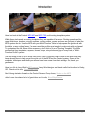
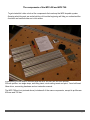
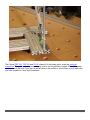
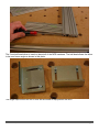
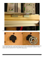
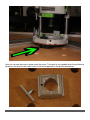
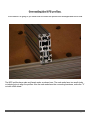
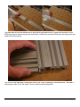
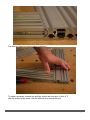
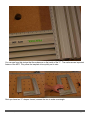
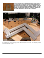
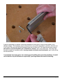
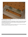
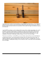
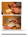
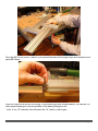
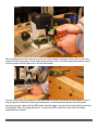
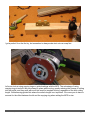
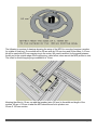
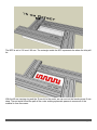
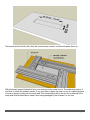
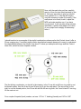
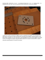
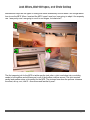
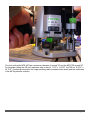
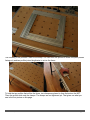
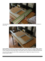
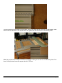
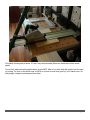
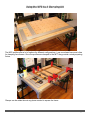
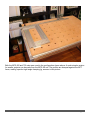
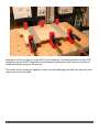
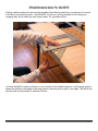
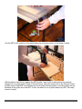
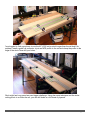
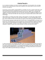
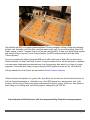
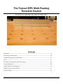
The Festool MFS Multi-Routing Template System A User's Guide by Brice Burrell Contents Introduction ..................................................................................................................................................2 Connecting the MFS profiles. ................................................................................................................... 10 Template Routing with the MFS System .................................................................................................. 17 Inlays .......................................................................................................................................................... 27 Jack Miters, Stair Stringers, and Circle Cutting ....................................................................................... 41 Cutting Applications .................................................................................................................................. 58 Using the MFS As A Clamping Aid ............................................................................................................ 71 Miscellaneous Uses For the MFS ............................................................................................................. 74 Closing Thoughts ....................................................................................................................................... 78 © 2008-2009, Brice Burrell Page 1 Introduction Here is a look at the Festool MFS 400 and MFS 700, multi-routing template system. While these tools excel as routing templates they are capable of far more. Routing operations like open-field inlays, borders, cutouts, mortises, routing circles, curves and arcs are just part of what the MFS system can do. Use the MFS with your Multi Function Table to help square the guide rail with the table, or as a cutting fence. I've even used the profiles as a temple to make cuts with my jigsaw! To understand the full value of this accessory, don't think of it as a "Routing Template". Envision profiles that form templates, squares, fences, stops, story sticks and jigs of every kind, a "MultiFunction Profile" system. The first thing I'd like to do is credit Jerry Work, Ned Young and John Lucas for the work that they have already done to help us get the most out of the MFS and the Festool system. Some of the methods, techniques and ideas you will see here have come from their writings. So, thank you gentlemen. Here is a link to Jerry Work's MFS manual. Jerry Work designs and hand crafts fine furniture in Kerby, OR. Check out his site, The Dovetail Joint. Ned Young started a thread on the Festool Owners Group forum, Notes on the MFS. John Lucas has shared a lot of great ideas on his site, WoodShopDemos. © 2008-2009, Brice Burrell Page 2 The components of the MFS 400 and MFS 700. To get started let’s take a look at the components that make up the MFS template system. Knowing what the parts are and what they do from the beginning will help you understand the functions and methods later on in this review. In this photo you see what is included with the MFS 400 set: two 400 mm and two 200 mm profiles, two angle stops, anti-tilting insert, circle-cutting insert and pivot, 3 mm ball head Allen driver, connecting hardware and an instruction manual. The MFS 700 set (not pictured above) includes all of the same components, except its profiles are 400 mm and 700 mm. © 2008-2009, Brice Burrell Page 3 The MFS profiles are aluminum extrusions with graduated metric scales printed on them. Profiles are 80 mm wide and 16 mm thick with a series of "Joiner" or "V" slots and "Clamp" slots. The Joiner or V slots are for the connecting hardware, circle-cutting insert and pivot and the coupling hardware (not included with the sets) for joining profiles length-wise. I'll go into detail on how to join the profiles in its own section in this review. © 2008-2009, Brice Burrell Page 4 The Festool FSZ 120, FSZ 300 and FS-HZ clamps fit in the clamp slots, as do the guide rail connectors. The guide connectors can also be used to join the profiles in length. Also, 1/4" square and hex nuts fit the slots if you want to add a fixture to the profiles or mount them to jig or table with your own (imperial or “inch” style) hardware. © 2008-2009, Brice Burrell Page 5 The 3 mm ball head driver is used on almost all of the MFS hardware. The ball head allows the driver to be used on an angle as shown in this photo. The angle stops mount into the V slots and are used to help position the MFS . © 2008-2009, Brice Burrell Page 6 Here the angle stops are mounted on the bottom of the MFS to precisely locate the MFS for an inlay. This is the anti-tilting insert. It is used to prevent the router from tipping or tilting during routing operations. If the router is tilted the work piece can be ruined. Copying rings fit into the anti-tilting insert, this allows it to travel with the router. The insert can fit 24, 27, 30 and 40 mm copying rings. © 2008-2009, Brice Burrell Page 7 Here you can see the insert in place under the router. The insert is only needed when the profiles are spread too far apart for the router's base to be fully supported by the profiles themselves. © 2008-2009, Brice Burrell Page 8 This is the circle-cutting insert and pivot. I'll go into more detail about how to use the MFS to rout circles, curves and arcs later in this review. Festool offers some other accessories not shown in this review. Longer profiles are available, 1000 mm profiles and 2000 mm profiles to extend the MFS template system. You can use the Routing Slide with the MFS to support the router when routing out large areas, for example open field inlays. Also offered, as spare parts, are a set of 4 MFS "Joiners" (part # 493235) that fit into the V slots to connect profiles length-wise. You'll need to call Festool's service department to order the joiners. © 2008-2009, Brice Burrell Page 9 Connecting the MFS profiles. In this section I'm going to you show how to connect the profiles into rectangles and end-to-end. The MFS profiles have male and female ends, as shown here. The male ends have two small studs or indexing pins to align the profiles. Also the male ends have the connecting hardware, notice the "V" nut with a ball detent. © 2008-2009, Brice Burrell Page 10 The male end fits into the female end to align the profiles end-to-end. A guide rail connector or the MFS joiner can be used to secure the connection. Guide rail connectors (fitted into the clamp slot) are used in the photo above. The V nut on the male end of the profile fits into the V slot in the edge of another profile. The male's indexing pins also fit into the edge V slots to ensure perfect alignment. © 2008-2009, Brice Burrell Page 11 This shot is a close-up of two profiles connected. To make a rectangle, connect two profiles, a short and long one, to form a "L" with the scales on the inside. Use the Allen driver to secure the joint. © 2008-2009, Brice Burrell Page 12 You can see from this picture that the scales are on the inside of the "L". The scales are an important feature of the MFS. They allow the template to be quickly set to size. Once you have two "L" shapes formed, connect the two to make a rectangle. © 2008-2009, Brice Burrell Page 13 You can adjust the sizes of the MFS rectangles by moving the sort of "L" shaped pairs to set the width and length. At first, assembling the profiles can be kind of tough, but after doing it a few times you get the feel for it. I've sprayed my profiles, including the hardware, with a dry lubricant. This helps reduce some of the friction while adjusting them. As another added benefit, it lets tools slide on them easily. By combining sets and/or the longer profiles, different shapes can be made. This will greatly increase the usefulness of the system. © 2008-2009, Brice Burrell Page 14 It may be necessary to add the connecting hardware to both ends of some of the profiles to join different shapes. The hardware can be removed from one profile and added to another. The bolt and V nut have to be removed and the threaded insert can be taken out. The insert has an Allen recess, the insert is reverse threaded, turn clockwise to remove, use a 4 mm Allen key. The insert can then be screwed into another profile, turning counter-clockwise (anti-clockwise), and it will self tap into the aluminum. I recommend exercising great care removing and installing the connecting hardware, it would not be hard to strip the aluminum, especially if you forget about the reverse threading. © 2008-2009, Brice Burrell Page 15 The angle stops have V nuts that slide into the V slots to mount the stops to the profiles. The stops can be mounted square or on an angle. Connecting the profiles can be tricky in the beginning as I've already mentioned, sometimes you wish you had another set of hands to line up all of the hardware. The key is to be patient when connecting and adjusting the MFS profiles. Taking the time to perfectly set the template will show in the end results you achieve with this system. Moving on to using the MFS system, it's hard to know what to cover first. I think most people imagine the MFS being used as a routing template, so why not start there. © 2008-2009, Brice Burrell Page 16 Template Routing with the MFS System Routing inlays, borders, cutouts, mortises, circles, curves and arcs can be very accurately done with the MFS. I know my results are much better now that I'm using the MFS instead of the wooden jigs and fixtures I've used in the past. Template routing with the MFS is a fairly straightforward concept. However, there are a few things to keep in mind when deciding how to use and set up this system as a routing template, I'll go over some of them in this section, as well as show you how I use the MFS for my routing projects. If you happen to be unfamiliar with what template routing is, I'll explain. It is using a jig, fixture or in this case, the MFS profiles to guide a router's travel. The router must have a copying ring (guide bushing) or a bit with a bearing to prevent the bit from cutting into the template as it travels. When using a bit with a bearing, like a flush cut or pattern bit, the profiles can be set to the exact size needed, whether it is a cutout or mortise. This really simplifies the setup. However, using a pattern bit is not without its risks. The issue is with the bit accidentally cutting into the template/profile. This can happen one of two ways. First, while plunging the bit into the work piece, before the bearing can engage the template (with the bearing still above the profile) it can't stop the bit from going astray and doing bad things to your profile. The second issue occurs if the bearing happens to land in the V slot in the edge of the profile. You can run into this with smaller bits as they usually have small bearings that can fall into the slot. © 2008-2009, Brice Burrell Page 17 The picture above shows the potential dangers of using a pattern bit with the MFS. I'm not suggesting pattern bits can't be used, but, care must be taken when selecting the right bit. Bearing size, cutting length and diameter should all factor into the decision. When used in the right circumstances they can be a real asset. I use the MFS most often to rout for hardware like lock sets, strikes, latches and catches, but, most of all hinges. I've made all kinds of jigs to rout hinges, all of them out of wood or MDF. While they do work, it is usually only a short time before they become inaccurate from relatively light use. If you have ever used a wooden jig you know what I mean. I've had to add very thin shims to my hinge templates to finish jobs, not wanting to make a new jig to rout one or two more hinges. That drove me nuts! Now, I use the MFS, it is so much faster, easier and far more accurate than the wooden jigs ever were. I can set up the MFS and make a test cut in about five minutes or less. If it needs to be adjusted, that can usually be done in less than one minute. If a wooden jig is off, you're stuck shimming or remaking the entire jig. So let me show you how I use the MFS with a small pattern bit to rout hinges. © 2008-2009, Brice Burrell Page 18 The first step is to mark the setback for the hinge. I'll use this line to index the MFS. With the small pattern bit I use to rout my hinges I can set the MFS to the exact length of the hinge. The width is set wide enough so I can test fit the hinge without removing the MFS. © 2008-2009, Brice Burrell Page 19 Once the MFS is set to size, I place it on the pencil line then set the angle stops and clamp the work piece/MFS down. Here is a close look at the bit I'll be using. It is the same type that I showed earlier, you can see I've add a second bearing to solve the problem of the bearing falling into the V slot. It is a 1/2" diameter; this will match the 1/4" radius on the hinges. © 2008-2009, Brice Burrell Page 20 After installing the bit, the next step is to set the router's depth, plunge the router until it comes into contact with the work piece. This is called zeroing the bit. Now, I use the hinge itself between one of the turret stops and the depth rod to set the exact depth. It's time to rout, with the profiles set to be wider than the hinge, this leaves an open space for me to fully plunge the bit before contacting the work piece. I make systematic passes removing small amounts per pass. Again with the MFS wider than the hinge, I can test fit the hinge without removing the template. When I'm happy with the fit, I remove the MFS, test the fit once more, and make adjustments as needed. © 2008-2009, Brice Burrell Page 21 I got a perfect fit on the first try, but remember to always make test cuts on scrap first. Let's now look at using copying rings or guide bushings with the MFS. The advantage of using copying rings is twofold: they are always in place while routing, greatly reducing the chance of cutting into the profile; and they work with most bits used for template routing, regardless of the bit's cutting length. Unlike bearing-guided bits where the cutter's length is so important. Of course you do have to account for the offset between the bit and the copying ring when setting the MFS to size. © 2008-2009, Brice Burrell Page 22 The following is a series of drawings showing the setup of the MFS for a mortise (imagine a mortise for a table or chair leg). Our mortise will be 20 mm wide by 100 mm long and 50 mm deep. A 10 mm bit will be used with a 30 mm copying ring in the router. We need to account for the space between the bit and to the outside edge of the copying ring, called offset, when we set the MFS profiles to size. The offset for this bit/copying ring combination is 10 mm. Knowing the offset is 10 mm, we add that number twice (20 mm) to the width and length of the mortise. 40 mm x 120 mm is what the MFS should be set at to produce our 20 mm X 100 mm mortise. © 2008-2009, Brice Burrell Page 23 Clamp the MFS down where you want it, set the depth of the bit, and rout...... The result should be this, a mortise 20 mm X 100 mm X 50 mm. Working in metric makes setting the MFS to size pretty easy. However, I understand that most of you are much more comfortable working in imperial (inches). So let's do another mortise with imperial measurements, but this time I'll be cutting real wood. How about a mortise 3/4" wide, 3" long and 1/2" deep? In the router is a 1/2" straight bit with a 3/4" bushing. So the total offset I need to account for is 1/4". © 2008-2009, Brice Burrell Page 24 Setting the MFS to size in Imperial measurements I use a steel rule. With the offset added the dimensions are 1" X 3 1/4". With the MFS set to size, I place the template on the work piece, I've drawn lines to indicate were the MFS will be set and the mortise will be cut. Once everything has been set (MFS and the bit depth) and then clamped, I start the routing. © 2008-2009, Brice Burrell Page 25 A shallow mortise like this one only takes a few passes. The finished mortise. The angle stops make it a breeze to set the MFS up quickly when you need to rout the same location/size mortises on multiple work pieces. Just imagine the ease of routing traditional M&T joints for table and chair legs or mission style furniture. © 2008-2009, Brice Burrell Page 26 Inlays Inlays are a great way to add some interesting detail to your projects. The inlay I am going to do now is simple and small but it is going to have a huge impact on the piece. We start the same way as the rest of the examples, by selecting the bit/copying ring combo and setting the MFS to size. In the picture here I'm adding some scrap stock to act as shims to help support the MFS. © 2008-2009, Brice Burrell Page 27 More of the same; set the depth of the bit and rout. I need to be a little careful because I'm routing off each edge, and tear out can happen here. Removing small amounts near the edges will greatly reduce the chance of tear out. Here are the pieces I’ll be using for the inlay, zebra wood. © 2008-2009, Brice Burrell Page 28 With the pieces fitting perfectly, some blue tape will help hold the pieces in alignment until I can glue and clamp them. In the photo above the excess zebra wood has been cut off and the piece sanded. Using the MFS to rout this inlay was not much effort, but, added a lot of visual appeal to this piece. © 2008-2009, Brice Burrell Page 29 Taking offset routing one step farther, we'll take a look at making the male portion and female recess for inlays with the MFS. Keeping the MFS the same size and changing the copying rings/bits allows inlays to be cut quickly and accurately. You may be familiar with inlay sets available today. The sets have a bit and a guide bushing with a second bushing (with a larger diameter) that slips onto the first. With this type you follow the template to rout the female recess with both the guide bushing and second bushing installed on the router. Then, rout out the male insert with the larger second bushing removed, using the same template. I'll illustrate this principle with the MFS using different size bits and copying rings/guide bushings. © 2008-2009, Brice Burrell Page 30 This drawing shows how to use the same bit to rout the male and female potions of an inlay by changing the copying rings. In the drawing the 10 mm bit/20 mm copying ring combo cuts out the male inlay and the 10 mm bit/40 mm copying ring the female recess. The 40 mm copying ring with the 10 mm bit produces a 15 mm offset from the outside edge of the copying ring to the edge of the bit. With the 20 mm ring and 10 mm bit combo used for the male portion, the offset between the edge of the bit and the copying ring is 5 mm. When we add the 5mm offset and the 10 mm bit diameter we get 15 mm, equal to the offset of the female bit/ring combo. The goal is to have the offset of the female's combination of bit/ring be equal to the offset, plus the diameter of the bit used for the male portion. (Offset of Female bit/ring = Offset of Male bit/ring + bit diameter) Let me show the whole process with a few drawings using these same bit/ring combinations. This example will be an open field inlay 200 mm X 50 mm. © 2008-2009, Brice Burrell Page 31 The MFS is set to 230 mm X 80 mm. The rectangle inside the MFS represents the where the inlay will be. With the 40 mm copying ring and the 10 mm bit in the router, we can rout out the female recess 5 mm deep. The red arrow shows the path of the router making systematic passes to remove all of the material to form the recess. © 2008-2009, Brice Burrell Page 32 The recess should look like this. Note the corners have a radius; a chisel will square them up. With the female recess finished, let’s turn our attention to the male cut out. The male inlay stock is 5 mm thick to match the female's recess. It is a good idea to place the stock on top of a sacrificial piece of scrap to prevent cutting into the work table. Also the area that will be the cut out is adhered to the scrap with double-sided tape to keep it from being damaged by the bit when it is cut free. © 2008-2009, Brice Burrell Page 33 To make the male inlay piece I've installed the 20 mm ring, leaving the 10 mm bit in. To cut out the inlay, the router's depth is set to cut all the way through the 5 mm stock. In this picture, the red arrow indicates the router's path, only traveling around the template's perimeter. Here is the piece cut free. Unlike the female piece the male has square corners. © 2008-2009, Brice Burrell Page 34 Now, with the male inlay cut free, carefully remove it from the two sided tape and try the fit. If all goes according to plan you should have a perfect fit, or, one that will require very little trimming to make fit correctly. If the male piece is too small, trash it, adjust the MFS and make another one, if you have enough stock. It will only take a few minutes, remember, a prefect inlay adds to the value of your project and a sloppy fit takes away from it. I should mention in my example of the ring/bit combinations shown earlier that Festool doesn't offer a 20 mm copying ring. I used that ring/bit combo hypothetical example because it is easy to understand the relationships between the offsets. How about if I show you examples with rings and bits Festool does offer, as well as some imperial combos. The first bit/ring combination, on the left in the drawing, is the 10 mm bit and 40 mm ring used to rout the female recess, then the 6 mm bit and 24 mm ring to cut the male piece. The second set on the right, to rout the female portion, the 10 mm bit with the 40 mm ring then, the 3 mm bit and 27 mm ring for the male cut out. For a couple of imperial (inch) combos, set one: 1/2" bit / 1" bushing (female) and 1/8" bit / 3/8" © 2008-2009, Brice Burrell Page 35 bushing (male). Second set: 1/2" bit / 1 1/4" bushing (female) and 1/4" bit / 1/2" bushing (male). The examples given are only a few of the possible bit/ring combinations commonly available. I want to fit a router into this piece of MDF to act as a makeshift router table I can set between two saw horses on the job site. This is the plate I'll be recessing into the MDF. Fitting the plate is a twostep process, making a cutout for the router to pass through and a recessed lip or rebate for the plate to sit on. First thing is to measure the plate and the radius of its corners to set the MFS on, and to choose the right diameter bit to match the corners. © 2008-2009, Brice Burrell Page 36 I decided to make the cutout first; the router has a 1/4" spiral bit with a 1 1/2" bushing. The bit is set to cut all of the way through the MDF, so I placed a scrap under the work piece to protect my MFT's top. I'll guide the router slowly around the template. © 2008-2009, Brice Burrell Page 37 I've switched to my OF1400 router to make the lip for the plate. I've already put an 18 mm bit and a 30 mm copying ring in the router, I set the MFS for the 7 mm offset. The 18 mm bit should fit the radius on the corners of the plate perfectly. © 2008-2009, Brice Burrell Page 38 This picture shows the lip routed in, now, I'll test fit the plate. It looks like I've got the fit right on the first try. There isn't much of a learning curve to setting up the MFS. It didn't take me long before I got perfect results, the first time every time. © 2008-2009, Brice Burrell Page 39 The process, from start to finish, was only about 15 minutes, and that was while shooting the pictures too. © 2008-2009, Brice Burrell Page 40 Jack Miters, Stair Stringers, and Circle Cutting Mortises and inlays are the types of routing that came immediately to mind when I first thought about how to use the MFS. When I received the MFS I wasn't sure how I was going to adapt it for carpentry use. I was pretty sure I was going to use it to rout hinges, but what else? The first carpentry job for the MFS to tackle was the jack miter, a joint used when trim or molding needs to butt together and still have part or all of the profiles continue around. This joint requires careful and precise setup, a job perfect for the MFS. The pictures here show the process: measure the offset, set up, rout, test fit…does this sound familiar by now? © 2008-2009, Brice Burrell Page 41 The finished joint. With some creative thinking, the MFS made this tough routing job easy! Check out the story over at my "How To" page Jack miter page. © 2008-2009, Brice Burrell Page 42 I also routed stringers for a small staircase. This is where having both the MFS 400 and 700 sets really paid off. Two sets allowed me to make the L-shaped template I needed to rout in the treads and risers for this job. You may never need to rout stringers, but it is nice to know you can. More details can be found in my "Projects" page, Small Staircase. © 2008-2009, Brice Burrell Page 43 Now we’ll move from using the router to travel around the MFS as a template, to moving the router and template on a pivot to create circles, curves and arcs. I'll start with a quick overview of the process for circle cutting before I go into detail. The circle-cutting insert fits into the interior V grooves of the profiles, the template is closed on and capturing the insert (see photo above). A 30 mm copying ring fits into the insert, so the next thing to do is install the ring in the router. © 2008-2009, Brice Burrell Page 44 The pivot goes in the underside of the profiles, in the V groove closest to the inside of the template. Slide the pivot in as far as it will go, then tighten it with the Allen driver. We need a hole for the pivot to go into. An 8 mm or 5/16" drill bit will do the job. © 2008-2009, Brice Burrell Page 45 Slip the pivot in the pilot hole, set the insert to the desired radius and tighten it in place, then set the copying ring/router in the insert. The template and router pivot around the stock to cut the circle. You can see from the picture that I'm working out the process on scrap first before committing to the real work piece. I initially thought using the MFS to cut circles would be a little awkward; turns out I was wrong. However, setting the size of the MFS to cut circles for the first time was a bit of a challenge for me. Well, until I realized the instructions show the insert installed incorrectly. I have some drawings to help illustrate the setup. © 2008-2009, Brice Burrell Page 46 I'm going to start by showing the finished piece for this example so you can see what I am setting up to rout, a cutout with a lip or rebate. Step one is to lay out for the pivot point, then drill the pilot hole. © 2008-2009, Brice Burrell Page 47 The next step is to set the insert to rout the proper size circle, the pivot is already installed. Before we move to the next step, let me explain the set up process in detail. The insert is set using the scale on the MFS profile and the insert's own scale. The insert's scale is not centered on the hole for the copying ring (see picture above), at first that doesn't seem make much sense. But remember the pivot is offset from the profile's scale, this accounts for the insert's offset scale (say that three times fast). Now, take into account the bit, its cutting edges are offset from the zero point on the insert. I know, a lot of offsets here, so let me show you a couple of drawings to help clarify things. © 2008-2009, Brice Burrell Page 48 This drawing shows the insert. The scale is larger in this picture than the real one, to make it a little easier to see. The first thing to notice, the scale has graduations on both sides of zero. Zero is the centerline of the cut. The graduations above zero (towards the top of this drawing) represent the outside of the cutting radius, also referred to as R2 in this drawing. And the gradations below zero are the inside radius or R1. In this example a 10 mm bit is used, the outside radius is plus 5 mm from zero and the inside radius is minus 5 mm. This drawing shows how to set the insert with the MFS scale. With the 10 mm bit, the insert is set to cut a 310 mm outside radius and 300 mm inside radius. © 2008-2009, Brice Burrell Page 49 All right, back to the example. I have a 10 mm bit in the router and the insert set to cut a 100 mm outside radius (90 mm inside). My MFT has a piece of scrap on it to protect the top, and the work piece has double-sided tape to hold it down to the scrap. I've dropped the pivot in the pilot hole, set the depth of the bit to 8 mm. Plunge the router and start turning the template on the pivot to rout the circle. © 2008-2009, Brice Burrell Page 50 Here is the result. Now I want the center cut out, leaving the lip. I've changed bits, a 6 mm spiral bit now in the router. I'll move the insert to cut a 90 mm outside radius for the 6 mm bit. The depth is set to cut all the way through the stock. © 2008-2009, Brice Burrell Page 51 Remove the center cutout from the double-sided tape and that takes us back to the finished piece, the first picture at the top of page 47. © 2008-2009, Brice Burrell Page 52 For circle cutting the MFS 400 has a maximum diameter of around 32" and the MFS 700 around 55". For template routing the 400 set's maximum size is about 4 11/16" x 12 9/16", the 700 set 12 9/16" x 24 7/16". Combining sets and/or the longer profiles greatly increases these sizes (and the usefulness of the MFS system as a whole). © 2008-2009, Brice Burrell Page 53 I've found making overlapping, systematic passes while template routing offers the best results. I always check to make sure I haven't missed any spots and the bottom of the routed area is perfectly flat. Be sure to test fit your work before removing the template anytime you can. It is difficult is get the template back exactly where it was to rout a missed spot. Another tip, test your bit and copying ring combinations on scrap stock first to ensure the results are what you expect. Remember the MFS is as accurate as you set it up to be, so give it the time it requires. Calipers help me set the MFS for smaller work where the routing being off the tiniest amount is not acceptable. © 2008-2009, Brice Burrell Page 54 Adding profiles with the angle stops to the outside of the template helps to place and clamp the MFS. The anti-tilt insert is made to fit 24, 27, 30 and 40 mm copying rings. But, what if you want to use imperial sized guide bushings? No problem, just use the router's support foot (outrigger) to do the job. Holding the router flat on the template is the key. If the router tilts it can ruin your work piece, so exercise care. One more very important thing to mention: let the router bit come to a stop or release the plunge mechanism before lifting the router out of the template! If the bit contacts the template, you could damage the bit and most certainly cut into the profile. If the profile is cut where the bushing rides that edge of the profile, it will no longer produce true cuts. The profile is not ruined; it can be © 2008-2009, Brice Burrell Page 55 turned to have the blemish facing out or turned upside down. However, since you can’t use the scale, it can greatly affecting ease of set up. You'll notice the router's dust collection is not as good while routing with the MFS. The open space the template creates lets chips escape. The chips find their way into the profiles. If you let the chips build up in or around the profiles they can affect the template accuracy by getting between the copying ring and the template. I take time to vacuum off the template as needed. Placing the template on the work-piece perfectly flat is a must. Check to make sure it is still flat after you have clamped everything down. Again, make sure no chips are under the template. What I've shown in this section are just some of the routing jobs that can done with the MFS template. With a little practice (and imagination) you'll be able to do projects that you thought were beyond your skill level. If you are a novice woodworker, the MFS can have you creating more complicated projects in no time. Once you have a grasp of the basics, it's pretty easy to build on those skills. Because the concepts are the same from the simple mortise, to the more complicated routing tasks like intricate inlay work, your skills will build quickly. For the more experienced or the professional woodworker, the MFS simplifies some of the routing jobs we used to do with custom wooden or single purpose built jigs. If you happen to have accurate, well-made custom jigs, by all means use them. Building custom jigs can be time consuming, sort of a trial and error process. That's time I'd rather be spending in some other, more productive way. Plus, © 2008-2009, Brice Burrell Page 56 I'm glad not to store custom jigs anymore. I have a notebook, with what Ned Young calls "recipes," of the MFS settings used on past jobs. Sure you have to spend time assembling the template each time you want to use it. I happen to feel the flexibility the MFS offers outweighs the small amount of time spent on set up. Accuracy of the MFS is far better than almost any wooden jig I've ever made. My final comments on the MFS as a routing template, no matter if you are a beginner or a pro: the MFS is fast and easy to set up, the routing is accurate and the results are great. © 2008-2009, Brice Burrell Page 57 Cutting Applications Jerry Work in his manual shows how he uses the MFS as a fence for the MFT and as story sticks to place guide rails for cutting or routing. In this section I'll show how I have taken Jerry's techniques and adapted them to my own work. Using an MFS profile as a story stick is an easy way to accurately place Festool's guide rails. I use one of the angle stops with a profile to set razor blades to act as stops for the rail, John Lucas' idea. Install the angle stop in the profile, with the scale up. Using the scale I set the square on the measurement I want. Then butt the stop up to the square and tighten the bolts. © 2008-2009, Brice Burrell Page 58 With the profile lined up with the edge of the work piece and the stop butted to the end, I have a perfect story stick to help place the rail. Now it's as simple as sticking a razor blade in the work piece at the end of the profile. © 2008-2009, Brice Burrell Page 59 Registering the rubber edge of the guide rail off the blades will give me the exact location I want to cut this piece to. Be sure to remove the razor blades before you make the cut. Use this technique any time you need to make multiple cuts the same size. It works just as well with short or long rails. © 2008-2009, Brice Burrell Page 60 An often asked question on Internet forums is "How do I make narrow rips with the Festool plunge cut saw and guide rail?" Using the MFS 400 with my MFT is what I've found to be the easiest, fastest, safest and most accurate. In this picture you see the setup I use. Note the wooden fence extension (green arrow). This prevents the rip from being thrown forward if it gets caught in the blade. For the rest of the setup, the MFS is butted up to the MFT's fence, acting as stop to set the width of the rip. The stock is then placed against the fence and the MFS, clamped and ripped. © 2008-2009, Brice Burrell Page 61 Step one in the setup is to assemble the profiles with the scales on the outside and checking to make sure the setup is square. Now, I slide it under the guide rail and set the edge to be even with the rubber splinter guard on the rail. © 2008-2009, Brice Burrell Page 62 One of the things that makes this technique so fast and easy is using the scale on the MFS to set the width of the rip. With the MFS lined up with the rail make a pencil mark at the profile's zero point (end of the profile). With this mark I'll be able to use the scale, in reverse, to set the width of the rip. In this picture you see the MFS set to make a 10 mm rip. © 2008-2009, Brice Burrell Page 63 The MFS has to be clamped in place to prevent it from moving during the cut, I also clamp the stock to be extra safe. Then it's like any other cut, drop the rail, plunge the saw and cut. © 2008-2009, Brice Burrell Page 64 Here are a few 10 mm rips. When I want to make imperial (inch) widths I use a small combination square. I set it to the size I need, and then place it against the rubber edge with the blade of the square under the rail. Butt the MFS to the square's blade and clamp the MFS. © 2008-2009, Brice Burrell Page 65 Here is a look at Jerry Work's idea of how to use the MFS as a fence for cutting and routing with the MFT. It consists of profiles to form a square or rectangle and a single long profile as a fence. The scales on the profiles are used to set the distance from the square/rectangle to the guide rail's rubber splinter guard. I am intrigued by this setup, although I have yet to fully incorporate it into my work so far. I find myself using the profiles for other jobs and unable to dedicate them to the MFT. I think the addition of the longer 1000 mm profiles would allow me to take full advantage of this ingenious idea. © 2008-2009, Brice Burrell Page 66 The following is the process I used for the setup. I've used 400 mm profiles to make a square (scales facing out) and two profiles joined lengthwise to act as the fence. To hold the two profiles that will be the fence, two clamps are placed in from the bottom the MFT. Then the profiles slide onto the clamps. The clamps are not tightened yet. That gives me what you see in the first picture on this page. © 2008-2009, Brice Burrell Page 67 The next step in the process is to set the square to the guide rail's edge, like I did with the setup for narrow rips. Now the square is indexed perfectly with the guide rail, then the square gets clamped down. I want to calibrate the scale on the fence profiles with the square's scale. However, I'm going to offset them by 10 mm. Holding the fence profiles tight to the square I want to line up the 39 cm mark with the fence's zero mark at the end of the profile. With everything lined up I'll tighten the clamps for the fence profiles (under the MFT). © 2008-2009, Brice Burrell Page 68 This is a close up of the offset of the scales. The 39 cm mark on the zero point of the fence's scale. Now to set the distance of the square from the guide rail I use the scale on the fence profile. Slide the square to the distance needed and clamp it. Now you can cut or rout the work piece. The insert in the picture shows the square is set to 290 mm. © 2008-2009, Brice Burrell Page 69 This setup shows great promise. It's fast, easy and accurate (there are those same three words again). I've not fully explored cutting applications for the MFS. Most of my time with this system has focused on routing. I'm sure to find more uses for MFS to cut and rout as time goes by. As it stands now, I'm fairly happy using the techniques shown here. © 2008-2009, Brice Burrell Page 70 Using the MFS As A Clamping Aid The MFS profiles offer a lot of options for different configurations. I use one shown here most often for clamping face frames. Once the profiles are clamped to the MFT they provide a sturdy squaring fixture. Clamps can be added almost any place needed to square the frame. © 2008-2009, Brice Burrell Page 71 Both the MFS 400 and 700 sets were used in the configuration shown above. A much simpler version for smaller projects can be made from the MFS 400 set. The profiles are clamped against the MFT fence, making a perfect right angle clamping jig, as seen in this picture. © 2008-2009, Brice Burrell Page 72 Squaring is not the only way to use the MFS to aid in clamping. I've used my profiles as cauls. With clamps from below the MFT the profiles can be clamped, pressing the stock down onto the bars of the parallel clamps, giving me flat glue ups. The profiles can be quickly put together to make a custom clamping jig and when the glue dries, take them apart for the next project. © 2008-2009, Brice Burrell Page 73 Miscellaneous Uses For the MFS Finding creative solutions to the everyday problems that affect productivity or enjoyment of our work is the key to successful projects. I use the MFS, not just as a routing template or as cutting and clamping aids, but to make any task easier, faster. It’s a problem solver. I've used the MFS to index my Domino to cut mortises in the middle of panels. I set the angle stops to square the profiles to the edge of the work piece so the zero point is right on the edge. This will let me use the scale on the profiles to index the Domino. © 2008-2009, Brice Burrell Page 74 I set the MFS to the location on the panel where the mortises will be cut and clamp in down. With the base of the Domino against the MFS profile, I can cut all of the mortises in a perfectly straight line, at a right angle to edge of the work piece. Using the center line on the Domino's base and the scale on the MFS, the mortises can be cut quickly and accurately. I would normally use the backside of the guide rail on the MFT for this, but when I'm on a jobsite without my MFT this really comes in handy. © 2008-2009, Brice Burrell Page 75 I've struggled to find a good way to use the 42" LR32 rail on stock longer than the rail itself. No problem; install a guide rail connector to join an MFS profile to the rail and clamp the profile to the edge of the stock. Now drill your holes. Stock eight feet long posed an even bigger challenge. Using the same technique and the circlecutting pivots to re-index the rail, you can drill holes in a full sheet of plywood. © 2008-2009, Brice Burrell Page 76 How about a jig to cut toe kicks for cabinets? One edge of the saw's base rides against the profile and the second profile acts as a stop for the cut. The first picture shows the setup, the angles stops are on both the top and bottom of the profiles to index the jig. Second photo, I'm holding the jig and making the first cut. Third, I've flipped over and turned the jig 90 degrees to make the second cut. Fourth, the finished toe kick. I can make the cuts in less time it would have taken to do the layout. It’s easy, fast and, you guessed it, accurate. Again, the MFS flexibility is shown here. Finding different uses, both within the Festool system and out, for the MFS is only as far away as your imagination. © 2008-2009, Brice Burrell Page 77 Closing Thoughts As I've touched on already, this review of the MFS system has a recurring theme: Easy, Fast and Accurate. Add to those attributes a great deal of flexibility of the system and the value of the MFS becomes very apparent. Let me give you one example of why the MFS is so valuable to my work. I get jobs a few times a year where homeowners want to upgrade their old, hollow core doors to a much nicer, solid core doors. This means routing for hinges and other hardware in the new door. Blanks, jigs or templates are needed to quickly and accurately do the job. In the past I would have to spend time making all of the different jigs. I could need the table saw, chop saw, jig saw, compressor/brad nailer and the stock to build the jigs. With the MFS I only spend a few minutes setting up the template to rout the hinges. When finished with all of the hinges, I readjust it for the next piece of hardware. I've tried other adjustable routing jigs; some I've liked and some I wouldn't even use again to scrape chewing gum off the sidewalk. But for the most part, they were not the right tool for the job. Now, I only keep the MFS on the truck. It's so easy to use I can hand the job off to one of my guys so I can turn my attention elsewhere. Being able to get in and out of a job quickly and not having to come back because of poor quality work is how I make my work profitable. The MFS is a real help in this regard. You don't need to be a finish carpenter to realize the same time savings and ease of use that I've found with the MFS. To take full advantage of the flexibility of the MFS system I'd recommend both the MFS 400 and 700 sets. I found I tend to use the smaller 400 set for most of my template routing, but the larger 700 set for cutting and clamping applications. If your budget doesn't allow for both, take a close look at your particular needs and decide which set best suits them. You can always add another set and/or the longer 1000 or 2000 mm profiles later as your needs grow. © 2008-2009, Brice Burrell Page 78 The flexibility the MFS is its single greatest attribute. Routing template, cutting, routing and clamping aid all in one. Normally I don't buy into a tool that claims to do it all. You know the saying, "jack of all trades, master of none.” However, that is not the case with the MFS. It does all of these things equally well and all of them very well. In true Festool fashion, the MFS meshes perfectly with the entire "Festool System". I've not yet reached the limits of what the MFS has to offer, that's part of what I like so much about Festool products. It's what I call "built in value". It may be unseen at first, but the solution to a problem or a new easier, faster and more accurate way to do the everyday jobs we do for a living or for pure enjoyment. Good luck and I hope you enjoy using the MFS system as much as I do. -Brice Burrell Visit my website for more Festool tips and reviews, Burrell Custom Carpentry. I'd like to thank a few people, first, goes to Mr. Jerry Work, his manuals are the foundation that we all built our Festool knowledge on. I had the luxury of his MFS manual as a starting point, also, John Lucas for all he's done to help users better understand the Festool system, thank you. Also thanks to Ned Young for his editing work and Noel Nyman for helping with this PDF file. In the interests of full disclosure, this tool was provided by Festool for review purposes. © 2008-2009, Brice Burrell Page 79