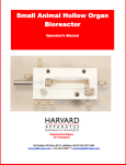
1
Large Animal Hollow Organ Bioreactor Operator’s Manual 84 October Hill Drive, Holliston, MA 01746 USA www.HARTregen.com 774.233.7300tele [email protected] 1 Revision 1.1 Sept 17, 2014 Contents Contents 2 Overview 3 Symbols 4 5 Warning & Caution Statements General Safety Requirements Chapter 1 - Introduction 1.1 Equipment Components & General Overview 6 Chapter 2 - Operating Instructions 2.1 Sterilization 9 2.2 Surface Disinfection 10 2.3 Post-Sterilization Assembly 10 2.4 Fluid Connections & Flow Path Options 11 2.5 Chamber Assembly 12 2.6 Controller 14 2.7 Medium 14 2.8 Medium Connections 15 2.9 Affixing the Organ / Scaffold 16 Chapter 3 - Care & Maintenance 3.1 Cross-Infection Prevention / Universal Precautions 18 3.2 Cleaning 19 3.3 Specifications 19 3.4 Troubleshooting 19 3.5 FAQs 20 2 Revision 1.1 Sept 17, 2014 Harvard Apparatus Regenerative Technology (HART) partners with leading global scientists to provide specialized solutions. The company is uniquely positioned to develop advanced instrumentation to accelerate regenerative medicine, tissue engineering and cell therapy experimentation. From the beginning, HART works closely with leading global researchers to produce products with the highest levels of performance, quality and support necessary for the new challenges of your life science research. We look forward to working with you to develop new tools to assist you in solving these new challenges of regenerative medicine from the lab bench to the patient. There are hundreds of publications, in regenerative medicine and stem cell research, utilizing HART products. These products will serve the researcher and the physician to accelerate basic research and clinical translation. Disclaimer: Use of the LARGE ANIMAL HOLLOW ORGAN Bioreactor should be conducted by a trained operator. Harvard Apparatus Regenerative Technology (HART) does not warrant unauthorized use of this product. HART warrants the operation of the bioreactor for a period of one year under normal laboratory conditions. HART reserves the right to change the instructions for use and any related products at any time without any prior notice and is not liable for any damages arising out of any change and/or alteration of the contents or product. This product is for RESEARCH USE ONLY. Copyright © 2014, Harvard Apparatus Regenerative Technology. All rights reserved. Harvard Apparatus Regenerative Technology owns the intellectual property rights to the LARGE ANIMAL HOLLOW ORGAN Bioreactor. This material may not be reproduced, displayed, modified, or distributed without the expressed prior written permission of the copyright holder. U.S., international, and foreign patent applications are pending. 3 Revision 1.1 Sept 17, 2014 Symbol Definition Date of Manufacture Serial Number Catalogue Number Warning: This action will have a direct impact on the patient Caution: This action will have an impact on the product or operator Manufacturer This device complies with Directive 2006/95/EC relating to electrical equipment designed for use within certain voltage limits; this device also complies with Directive 2004/108/EC relating to electromagnetic compatibility. 4 Revision 1.1 Sept 17, 2014 Warning and Caution Statements The use of a WARNING statement in this User Manual alerts you to a potential safety hazard. Failure to observe a warning may result in a serious injury to the user. The use of a CAUTION statement in this User Manual alerts you to where special care is necessary for the safe and effective use of the product. Failure to observe a caution may result in minor injury to the user or damage to the product or other property. Intended Use The LARGE ANIMAL HOLLOW ORGAN Bioreactor is a vessel used to support a hollow organ scaffold for the purpose of cell-seeding; it is intended for research use only. WARNING: Use of this device in non-research settings must be conducted under local Regulatory requirements; consult your local Regulatory Authority. The following conditions must be met prior to using the Bioreactor: General Safety Requirements WARNING: The Bioreactor should only be used by qualified personnel who have been trained by the manufacturer or other authorized representative. Unauthorized use of this device is not recommended. WARNING: To prevent contamination, aseptic procedures must be followed and personal protective equipment must be worn at all times when handling and using the Bioreactor. WARNING: Wherever blood products are used, Universal Precautions must be followed. WARNING: DO NOT SUPPLY EXPLOSIVE GASES TO THE BIOREACTOR Facility Requirements Assure that the facility is able to provide a clean, safe, and suitable area for aseptic cell processing. It is recommend that all manipulations of the unit once sterile are performed in a biological safety cabinet (laminar flow hood). WARNING: Failure to provide a means to conduct aseptic cell processing may result in harmful contamination. 5 Revision 1.1 Sept 17, 2014 Chapter 1: Introduction The LARGE ANIMAL HOLLOW ORGAN Bioreactor is a rotating, double chamber bioreactor designed for cell seeding and culturing both surfaces of a tubular matrix and includes rotational movement of the scaffold around its longitudinal axis. A polymeric chamber houses the biological materials throughout the culture period. Cylindrical scaffold holders are constructed with working end of different diameters—to house matrices of diverse dimensions—and a central portion of smaller diameter to expose the luminal surface of the matrix for cell seeding and culturing. A co-axial conduit links the inner chamber to the external environment through the chamber wall. This provides access to seed and feed the luminal surface of the construct. Secondary elements moving with the scaffold holder induce continuous mixing of the culture medium to increase oxygenation and mass transport. 6 Revision 1.1 Sept 17, 2014 1.1 Equipment Components Part Name # Included Part # Bioreactor Assembly 1 1031570 Complete Drive Motor Assembly 1 1031206 Barb, 1/8” x NPT, 1/16” 2 1031029 Cannula, 14 Gauge 1 1032413 Chamber 1 1031507 Chamber Culture Lid 1 1032414 Chamber Transport Lid 1 1032415 Driveshaft 1 1030196 Fitting, Fem Luer Lok x 1-16 NPT 4 1030919 Kit, Lid Closures 3 1031631 Kit, Pins, Scaffold Retention 10 1031634 Organ Support Dam 1 1031509 Organ Support Lock 1 1031510 Organ Support Shaft 1 1031573 Organ Support, Outlet Side 1 1031587 Organ Support, Driveshaft Side 1 1031588 Pin Dowel, 3mm OD x 10mm length 1 1031567 Pin Dowel, 0.06” diameter x 0.5” length 6 1031624 Plug, Nylon 10 each 5 1031566 O-Ring, Silicone, 0.875 x 1.00 x 0.7 [Lg] 25 each 1 1031577 O-Ring, Silicone .375 x .25 x .065 (Drive shaft) xx each 4 xxxxxxx 1 1031575 Tool, Lock and Support Removal Accessories Part Name Part # Cap, Male Luer, Polypropylene 25 each 1031140 Nut, Clear 25 each 1031141 Nut, Green 25 each 1031142 Nut, Red 25 each 1031143 Organ Holder, 16 mm ID 1032066 Organ Holder, 18 mm ID 1032067 Organ Holder, 20 mm ID 1032068 Organ Holder, 22 mm ID 1032069 Organ Holder, 24 mm ID 1032095 Port, Swabable 25 each Note: An organ holder should be selected to use with the unit. 1031081 7 Revision 1.1 Sept 17, 2014 Recommended External Supplies: Sterilizing Strips Sterilizing Bags (250mm) Sterilizing Bags (350mm) Ethanol 70% (1L) Surgical suture thread with needle (size 4/0 or 3/0) Sterile serological pipette Sterile drape Sterile bottle (1L) PBS buffer, clinical grade (750ml) Culture medium (280ml) Inoculum (40ml) Male Luer integral lock ring plug (sterile) Laminar Flow Hood Adjustable Pipette CO2 Incubator Repipetter 8 Revision 1.1 Sept 17, 2014 Chapter 2: Operating Instructions Prior to Starting: Assure that all the requirements identified in this manual have been successfully met. Personnel using the LARGE ANIMAL HOLLOW ORGAN Bioreactor should read through this procedure in its entirety prior to using the device. Personnel should train on all processes and equipment prior to operating the Bioreactor. WARNING: Failure to follow aseptic techniques and failure to train on all processes and procedures prior to using the bioreactor may result in critical delays, contamination, and other harmful events 2.1 Sterilization Bioreactor Equipment for Sterilization Sterile Pouch Equipment Bag #1 Culture vessel Other bags Organ Holder Parts Drive Motor Wipe down DO NOT AUTOCLAVE Base Plate Control Unit Power Supply Before autoclaving, foil or autoclave wrap the following: 1. Reservoirs and connectors 2. Tubing ends 3. Luer fittings of all bioreactor connections (do not unscrew). Then, remove valves and drive shaft from the operating ports and place them into the storage ports. 9 Revision 1.1 Sept 17, 2014 2.2 Surface Disinfection Equipment Drive Motor & Base Plate Control unit Power Supply NOTE: Two operators are recommended for unpacking, disinfection and assembly. CAUTION: In the case where several bioreactors are being used simultaneously, a unique identifier should be placed on each bioreactor component to avoid parts being exchanged. Colored stickers have typically been used on each pouch. Similar precautions should be taken with components post sterilization. WARNING: Failure to follow the defined sterilization procedure may damage the bioreactor and make it unsuitable for use. 2.3 Post-Sterilization Assembly Assembly Preparation The bioreactor parts are delivered in sterile pouches. Unpacking and bioreactor assembly should be performed in a clean room environment provided by a laminar airflow cabinet. CAUTION: To prevent contamination, aseptic procedures must be followed and personal protective equipment must be worn at all times when handling and using the Bioreactor. CAUTION: Failure to strictly follow aseptic techniques may result in critical delays, contamination, and other harmful events. Sterile Bioreactor Equipment Other Materials Bioreactor Surgical suture thread with needle Arbor & organ sterilized in sterile pouch Sterile serological pipette Driveshaft Sterile bottle (1000 ml) Reservoir Cover PBS buffer Transport Cover Culture medium Inoculum Disinfected Bioreactor Equipment Drive unit Control unit Power Supply 10 Revision 1.1 Sept 17, 2014 2.4 Fluid Connections / Flow Path Options It is optional to apply RTV Sealant {1030566} to the threads of every port and fitting. A small amount, the size of a match head, should be applied to the thread to minimize the potential for leaks. Do not use too much RTV; a single drop will spread out and cover the entire area. Do not get sealant on the top of the fitting or the lids. When changing the fittings, use a Q-tip to clear debris while holding upside down to allow residue to fall out of chamber. Seal Wash Ports should be connected to a source of distilled water. An elevated inlet will provide enough pressure to allow flow through the ports. This will continuously wash the drive shaft and keep medium from drying and leaving salt crystals behind the seal which can cause damage to the seals and leaks. EL Inlet IC Port—this is used when the DAM is to the inlet side of the reservoir and the desire is to run the IC reservoir dry EC Port—this is used when the DAM is to the outlet side of the reservoir and the desire is to run the EC reservoir dry IL Inlet EC outlet {1031136} Seal Wash Ports {1031029} The level of the medium in the EC reservoir is selected by connecting a fitting to one of the three EC outlet ports on the reservoir or using the variable level outlet on the reservoir cover. Place fitting into culture lid. Add swabable port to the fitting. Push cannula through the swabable port. Adjust the height to provide the level of medium in the reservoir desired. Cannula {1032413} Swabable Port {1031081} Fitting {1031136} Culture Lid {1032414} IC and EC Inlets—There are two distinct flow path options: 1 Multiple independent Intra-Capillary (IC) and Extra Capillary (EC) flow paths. Allows the use of an independent medium to be perfused through the IC and the EC. Separate inlets and outlets are available. 2. Single flow path - Allows a single medium to be perfused through both the IC and EC flow paths. Separate inlets are available with a single outlet through the chamber. 11 Revision 1.1 Sept 17, 2014 2.5 Chamber Assembly Insert the O-ring {1031577} onto the Organ Support Outlet {1031587}. Place the small O-Ring {1030195} onto the end of the hex rod {1031588}. Push O-Ring in flush against the flex hole of the Support Outlet Dam. Lock, Organ Support {1031510} should be placed on the Dam {1031509}, Organ Support after Dowel Pin {1031567} is pressed into it. The Lock should swivel parallel to the Dam. Place three O-Rings {1030195} onto the driveshaft {1030196}. Insert the hex rod {1031573} and the driveshaft. 12 Revision 1.1 Sept 17, 2014 EC Outlet This fitting is seldom used as there is minimal room under the driveshaft. Typically a plug is installed. It allows an alternative EC outlet when the EC reservoir is being run dry. IC Outlet The Lock and Support Removal Tool {1031575} is used to remove the Organ Support Dam from the bioreactor. There are two lids available for the bioreactor. The culture lid (no O-Ring) {1032414} contains a hole which can have a tapered Fitting {1031136} that is a variable height EC outlet. If the port is not to be used as an EC outlet. A plug {1032416} should be placed in the hole. If using the variable EC outlet is being used, then a tapered fitting {1031136} is inserted into the hole on the lid. Attach a Swabable Port {1031081} followed by a 14 Gauge cannula {1032413}. The height of the media in the reservoir is adjusted by elevating the cannula. The cannula should be autoclaved separately and then inserted aseptically. DO NOT USE the transport lid {1032415} when the system is in the incubator as the O-Ring seals the top and does not allow gas flow. The transport lid is used when a sealed environment is required. Place the lid on the bioreactor and secure using the O-Rings {1031632} attached to the transport lid pins. Tubing Size: #13 #14 #16 #25 ml / min (for single pump head) 0.018 - 18 0.63 - 63 2.4 - 240 5.1 - 510 Inner Diameter in. (mm) 0.03” (0.8) 0.06” (1.6) 0.12” (3.1) 0.19” (4.8) Barb Size in. (mm) 1 /16” (1.6) 1 /16” (1.6) 1 /8” (3.2) 3 /16” (4.8) Outer Diameter in. (mm) 5 /32” (3.9) 3 /16” (4.8) 1 /4” (6.4) 5 /16” (7.9) Max Pressure-continuous psig (bar) 25 (1.7) 25 (1.7) 25 (1.7) 20 (1.4) Max Pressure-periodic psig (bar) 40 (2.7) 40 (2.7) 40 (2.7) 35 (2.4) Use in Single Channel Head YES YES YES YES Use in Dual Channel Head YES YES YES YES 1031101 1031102 1030340 1030339 Part Number (25 foot roll) (7.6m) 13 Revision 1.1 Sept 17, 2014 2.6 Controller The power module {1032418} should be connected to the power port Connect the Communication Cable from the controller to the bioreactor motor housing {1030280} The controller can be used on various models of bioreactors. Confirm that the switch is in the clockwise position. Otherwise the shaft will be rotated out of the bioreactor. Alarm can be switched to the ON position which allows the controller to verify that the motor is turning. The TEST position will test the audible alarm. The RPM switch allows selection of the revolutions per minute the shaft will be turned. The switch is turned clockwise to increase the rotational speed from 0.5 to 5 rpm. In order to select the rpm required, it is recommended that a stop watch is used to measure the turns made by the drive shaft and the knob adjusted accordingly. This should be done after the unit is in the incubator. The motor – tray is placed in an incubator with the connection wire normally fed through an access port or by compressing the door gasket. If the door gasket is compressed to allow the wire to pass, it is recommended that a piece of foam is glued to the wire to eliminate a space being formed above the wire and the inside door of the incubator. Place the bioreactor on the motor plate with the drive shaft connected to the motor. Note the clover leaf coupling should be in place. 2.7 Medium Replenishing feed medium can occur in a number of ways. When deciding on the manner of medium replenishment and removal that will be employed several factors should be taken into consideration including minimizing: The number of times the sterile flow path is opened to minimize the risk of contamination The volume of medium changed at a single time to not change the environment the cells are exposed due after they have conditioned the medium with the particular growth factors and cytokine cocktails they are accustomed to. The volume changed if the fresh medium temperature is different from the operating medium temperature. One manner to deal with the considerations above is to have a medium feed bottle large enough supply the entire amount of medium required throughout the experiment. This may slow the initial growth phase of the culture as it may take a bit more time for the cells to secrete the needed levels of cytokines to condition a larger volume of medium. However, in general this is the safest manner to minimize contamination. A second manner is to pour a volume, typically not more than 25-50% of the existing medium out and pour fresh medium in. Considerations for aseptic technique when handling large mouth reservoirs should be seriously studied. Another manner is to have an external bag (s) or large bottle (s) of medium and have the system automatically feed and remove small volumes of medium on a continuous basis. Fittings can be used to allow multiple inlet and outlet lines to feed into a single bottle. Clear Nut {1031141} Cap {1031139} T Fitting {1031138} Green Nut {1031142} Red Nut {1031143} Please note that it is recommended that the tubing inside the bottle be long enough to always be below the medium level. 14 Revision 1.1 Sept 17, 2014 2.8 Medium Connections Peristaltic Pumps Depending on the configuration of the system and how you set up the medium feed and waste will dictate the number of pumps and channels you will require. A typical configuration may be: EC Inlet tubing is selected according to the flow rate range required {see chart}. The EC is normally fed from a bottle inside the reservoir. EC Outlet tubing is selected according to the flow rate range required {see chart}. Typically the outlet flow rate is selected higher than the inlet to assure the unit does not over fill. IC Inlet and outlet tubing is selected according to the flow rate range required {see chart}. The IC is normally fed from a bottle inside the reservoir. IC Outlet tubing is selected according to the flow rate range required {see chart}. Typically the outlet flow rate is selected higher than the inlet to assure the unit does not over fill. This type of configuration would require 2 pumps with two channels each Placing the drive unit of the peristaltic pump inside the incubator is usually recommended to minimize the tubing length and thermal effects of having liquid moving in and out of the incubator. This also minimizes the number of tubes that have to go through an aces port or that have to be squeezed against a door gasket. Connecting the EL Circuit The EL inlet should be connected to a piece of Masterflex (see chart below) tubing through a Luer Barb Fitting to the EL reservoir. It is recommended that the user allows enough tubing length to not only complete the circuit to the EL outlet but with enough length to spare to allow the tubing to be moved an inch once per week. Moving the tubing an inch (out of the head) minimizes tubing wear on a single spot. The EL outlet should be selected according the to the medium level desired in the reservoir. The side of the chamber allows five choices. There are two choices that will allow running of the chamber virtually dry (1 & 2 below). The number 2 position can have issues with tubing fitting under the drive shaft if the tubing is too large. Both allow the exact functionality. Positions 3,4, & 5 allow the medium level to be fixed at three different levels. The variable level EL outlet on the Lid (6) may also be used. The level is selected by simply adjusting the level of the cannula tip. The IL Inlet should be connected to a piece of Masterflex {see chart} tubing through a Luer Barb Fitting to the IL reservoir. The positions #7 or #8 are identical. Position #7 may not be usable depending on the length of the scaffold which will dictate the dam location. We recommend that you allow enough tubing length to not only complete the circuit to the IL outlet but with enough length to spare to allow the tubing to be moved an inch each week. Moving the tubing an inch (out of the head) minimizes tubing wear on a single spot. EL Inlet IL Inlet 6 2 8 7 IC Port - this is used when the DAM is to the inlet side of the reservoir and the desire is to run the IC reservoir dry 1 4 3 5 EC outlet 15 Revision 1.1 Sept 17, 2014 2.9 Affixing the Scaffold / Organ to the Organ Holder First, lay out the relevant materials you will be needing. You should obtain the two Organ Holders, two pins {1031634}, and a pair of surgical forceps. Place the organ between the two Organ Supports. There are flat areas on each of the Organ Supports that allow the organ to lie stationary. The notches indicate where the pins should be placed. Use the forceps to place the pins, one at a time, in the four dedicated locations. An alternative is to suture the scaffold into place by wrapping the thread around the groove in the organ holder and pulling it tight. 16 Revision 1.1 Sept 17, 2014 Slide the driveshaft through the center of the lumen all the way to the other end of the organ. Using a biopsy punch, a sample of tissue can be taken post-incubation for further analysis if desired. This sample can now be used for testing. 17 Revision 1.1 Sept 17, 2014 Chapter 3: Care & Maintenance Cross-Infection Prevention, Biohazardous Waste, and Product Disposal 3.1 Cross-Infection Prevention / Universal Precautions All blood products or products potentially contaminated by blood or other body/animal fluids should be treated as potentially infectious materials. Personal protective equipment should be worn at all times when using the LARGE ANIMAL HOLLOW ORGAN Bioreactor to protect personnel from becoming contaminated as well as to help prevent cross-infection and cross-contamination. Bench tops, equipment, and other potentially contaminated surfaces should be cleaned and disinfected according to the manufacturers’ and/or the facility’s procedures. Any article used to clean potentially contaminated surfaces should be disposed of as Biohazardous Waste. CAUTION: Failure to use the manufacturers’ cleaning and disinfecting procedure could result in damage to the surface or equipment. Biohazardous Waste Dispose of biohazardous waste according to local Regulatory requirements. 3.2 Cleaning Flush all fluid paths with deionized water and either follow with or wipe with 70% IPA. These materials of construction will withstand virtually all biological reagents and cold sterilization agents. Stainless steel parts may be sonicated. 3.3 Specifications Size of Organ 0.7—9 mm ID, up to 65 mm in length is standard Rotation Speed 0 - 5 rpm Diagnostics Power Positional Monitoring 100-240 VAC, 50/60 Hz 18 Revision 1.1 Sept 17, 2014 3.4 Troubleshooting Arbor not turning: Check to see if the reservoir is in place and the drive shaft is connected to the motor. The retaining clamp is tightened during installation to maintain the connection. Check to see if the medium—blood being used has fouled the arbor. This can occur in high fibrinogen solutions. Excess Medium / Reagent build up in the reservoir: Check for clogging or fouling of the reservoir outlet line or port especially during a decellularization procedure. Medium level in the IC or EC flow path has gone dry: Confirm that there is sufficient medium in the inlet reservoirs and that the inlet tubing inside the reservoirs is below the medium level. Leaks: DO NOT USE BLEACH WHEN CLEANING THE BIOREACTOR AS IT HAS BEEN SHOWN TO CAUSE FAILURE OF COMPONENTS DURING AUTOCLAVE OPERATIONS. Also, be sure to check O-Rings frequently and replace as necessary. 19 Revision 1.1 Sept 17, 2014 3.5 Frequently Asked Questions What is the size of the standard organ holder? The typical organ holder has an ID of the hole leading to the intraluminal space of 12 mm. The OD can vary on the standard unit from 16 - 24 mm. For organs requiring 11– 12 mm OD a custom organ holder can be made. Should I sterilize using plasma sterilization or does autoclaving work? The materials of construction are Teflon reservoir, stainless steel baseplate, driveshaft, and valves, silicone rubber O-rings, Kynar luer fittings, polycarbonate cover, and PEEK arbor components. All of these materials will withstand steam sterilization. One CAUTION, however…. Please disassemble all the valve and driveshaft parts from the Teflon block before steam sterilization. The high temperature may cause the machined holes in the Teflon to become deformed by the parts pressed into them. Reinstall the valves and driveshaft after the Teflon cools down. The Kynar luer fittings have been installed using silicone adhesive to hold them in place and prevent leaks. It should not be necessary to remove these fittings from the Teflon because of the sterilization process. Can washing be done with [reagent]? These materials of construction will withstand virtually all biological reagents and cold sterilization agents (such as Cidex, Cidex OPA, Mucasol, etc.) How does the "seal wash inlet" and outlet work? This passage is designed to take a non-salt solution and flush it through a separate space between the two outside O-rings on the driveshaft. This will prevent any buildup of evaporated salt crystals from forming on the turning shaft during long periods of use. As an example, an intravenous drip bag with water set to between 0.1mL and 0.5mL per minute to continuously flush the seal wash path. Can I use the bioreactor for natural and synthetic scaffolds and organs? The bioreactor can be used for both types of organs. 20 Revision 1.1 Sept 17, 2014 Can I use Tygon tubing to save money? Tygon tubing is not recommended but can be used. The issue that arises all too frequently (even with the autoclave grade Tygon tubing) is that a piece of the tubing will crease and partially block during an autoclave cycle. It is very difficult to undo the crease and can cause issues. If Tygon tubing is used, it is highly recommended that tubing be removed from the fittings during the autoclave process. Otherwise the tubing should be taken off the fitting and the end clipped to present fresh tubing and then pushed back on the fitting. Otherwise the fatigue experienced as the different plastics expand at differential rates may cause the tubing to come undone during an experiment. Autoclave cycle settings It is highly recommended that the temperature cycle not exceed 121C as this can cause damage to various components of the bioreactor. What type of pump must I use for medium delivery? There is not actual requirement on the type of pump selected. In most cases people will use a peristaltic pump that allows the electronics to be outside the incubator with the drive motor inside. If you are using multiple pumps in the incubator or multiple bioreactors with multiple pumps, the ability of the incubator to maintain temperature may be an issue. Many types of incubators only heat and the use of multiple pumps may cause too much heat inside the incubator. If this is an issue, select an incubator that will heat and cool or contact the customer service group as the power to the pump motor may be lowered and this may aid with minimizing the heat. How do I vary the length of the scaffold holder? There is a sliding dam which divides the chamber into an IC and EC chamber. The slide allows a maximum length of 140 mm of an organ. The organ holder slides on a hexagonal drive rod. The standard organ holder has a 12 mm ID opening. There is a nipple where the organ is attached to is made with an OD diameter from 14 – 24 mm. Custom organ holders down to 11 mm OD with a smaller ID can be designed. 21 Revision 1.1 Sept 17, 2014 3.5 Frequently Asked Questions (cont.) What do I do if I want to use organs with an ID of less than 10 mm? A small hollow organ bioreactor chamber is available which can be used with the controller and motor drive of the large hollow organ bioreactor. 22 Revision 1.1 Sept 17, 2014 Notes: 23 Revision 1.1 Sept 17, 2014 84 October Hill Road, Holliston MA 01746 USA 774.233.7300 www.HARTregen.com [email protected] 24 Revision 1.1 Sept 17, 2014