1
QUAD-COL43 DUAL PAGE COLOUR QUAD USER’S MANUAL www.allthings.com.au
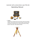
One Introduction
1. Summarization
Thank you for choosing our Dual Pages Color Quad . In this manual, you will learn major
features of the product, and how to install and operate with the product.
Notice: All the information contained in this manual is subject to change without notification
ahead of time, as we keep the right to update the product and offer updated manual.
2. Features and Functions
(1) Support 8 channels video input and display by dual pages
(2) Display time / date, and setup display position
(3) Video loss alarm
(4) Support 8 channels sensor alarm
(5) Auto dwell
(6) Support each record mode
(7) Zoom image while playback
(8) Remote control by RS232 and RS485 ports
(9) Relay alarm output
2
QUAD-COL43 DUAL PAGE COLOUR QUAD USER’S MANUAL www.allthings.com.au
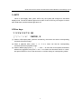
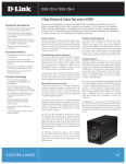
Two Front Panel Buttons
1. Front Panel View
2. MENU
(1) Press ‘MENU’ and hold for 2 seconds when the machine is in display or playback state, and
‘[PASSWORD:_
]’ will appear to require users to input password. The indicator light
will turn on the same time. Only by inputting the correct passwords, users can access to MENU
page to change / view settings.
(2) Press ‘MENU’ key once again to return to the upper menu or exist MENU page.
Notice: The password is the only identity proof. Please keep the password carefully and
well! The default password is 1111. In case users forget the customized password, press
‘MENU’ key and ‘VCR’ key simultaneously, and restart the machine, then users can recover
the password to default value.
3. VCR
(1) When in real display state, press ‘PLAY’, the machine begins to play files. The monitor
screen displays ‘PLAY’ in the upper side. Press ‘1’, ’2’, ’3’ or ’4’ to see corresponding
channel’s full screen image.
(2) When in real display state, press ‘PLAY’ for 2 seconds, user can see the playback images
of 4 cameras from ‘VCR IN’. There is no camera title displayed. The VCR indicator light
turns on then.
4.QUAD
(1) When in auto-dwell display state or real display state (not in MENU page), users press
‘QUAD’, the monitor will display CAM1 to CAM4 4CH images. The QUAD indicator light
turns on.
(2) When in 4CH real display state, press ‘QUAD’ once again, the monitor will display CAM5 to
CAM8 4CH images. The QUAD indicator light winks then.
(3) When in auto-dwell display state or real display state (not in MENU page), press ‘QUAD’
for 2 seconds, two pages will display on the screen by turn. The QUAD indicator light winks
in half the speed of that in item (2). Note: users can set the dwell time for each page in
MENU SYSTEM SET RECORD TIME
3
QUAD-COL43 DUAL PAGE COLOUR QUAD USER’S MANUAL www.allthings.com.au
5. AUTO
When in real display state, press ‘AUTO’ key, the system will change into auto-dwell
display mode. The AUTO indicator light turns on then. Press ‘AUTO’ key once again, to cancel
auto-dwell state, and the indicator light turns off.
6.Other keys
‘1’ ’2’’3’’4’’5’’6’’7’’8’ OR
‘:’ ‘;’ ‘<’ ‘=’ ‘+’ ‘ ’ ‘ENTER’, ‘8’
(1) When in 4CH display state, press the number key, then users can see the corresponding
channel’s full screen image.
(2) When in playback state, press ‘1’, ‘2’, ‘3’ or’4’, users can see the corresponding
channel’s full screen playback image.
(3) When in MENU page, press ‘F’ , ‘G’ ‘I’ and ‘J’ to move the cursor upward, downward,
leftward and rightward, and press ‘+’ and ‘-’ to increase and decrease values on cursor,
and press ‘ENTER’ to turn to the next menu or confirm change of corresponding values.
4
QUAD-COL43 DUAL PAGE COLOUR QUAD USER’S MANUAL www.allthings.com.au
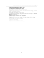
Three Menu Setup
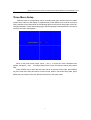
Please access to corresponding menus, including main menu and sub menus to make
system setup. When in real display or playback state, press MENU for 2 seconds, and input
user’s password in the area shown in the following figure to enter menu setup page. Users can
change password in certain menu setup page. Without inputting correct password, user cannot
access to the menu setup pages.
When in the menu setup pages, press ‘F’ and ‘G’ to move the cursor downward and
upward, and press ‘+’ and ‘ ’ to change values on the cursor, and save the values at the same
time.
Press ‘ENTER’ key to enter the sub menu. When in the main menu page, press MENU
key, then exist menu setup and return to former mode. When in sub menu setup state, press
MENU key, the present sub menu will exist and return to the upper menu.
5
QUAD-COL43 DUAL PAGE COLOUR QUAD USER’S MANUAL www.allthings.com.au
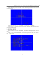
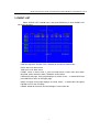
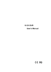
Press ‘MENU’ key, hold for 2 seconds, and then input the right password, users can enter
the following page:
At the right bottom, the driver and hardware version numbers are displayed.
In case there is no action with the menu for 3 minutes, the system will automatically return
to the former display mode.
1. SYSTEM SETUP
Select ‘SYSTEM SET’ in the MAIN MENU, and enter the following SYSTEM SET sub
menu:
Press ‘F’ and ‘G’ to move upward and downward among the setup items, then press ‘+’
and ‘ ’ to set values.
6
QUAD-COL43 DUAL PAGE COLOUR QUAD USER’S MANUAL www.allthings.com.au
TIME: System date and time. The default ASIA time and date formats are:
YYYY/MM/DD (Year/Month/Day), HH/MM/SS (Hour/Minute/Second)
FORMAT: Date format. Users can select among ASIA format, U.S. format and EURO
format.
LIVE TIME DISP: Time and date display position. TOP: top center, TOP_LEFT: top left,
TOP_RIGHT: top right, NON: no display
BORDER DISP: rim color. Three color options: GRAY, WHITE and BLACK, and users
can also select OFF
BACK COLOR: background color. Two options: BLUE and BLACK
VFILTER: video filter. ON: soft, OFF: sharp and clear
BUZZER: buzzer alarm. ON: switch on, OFF: switch off
ALARM TIME: select alarm holding time, 3 to 255 seconds adjustable
DWELL TIME: auto dwell time when in each record mode (share-time record mode)
PASSWORD: user’s 4 digits password. Any number composed by 1 to 8.
FORMAT: video format. Two options: PAL and NTSC. PAL is the default setting.
PROTOCOL: communication protocol. Four options: PTC1, PTC2, PTC3, PTC4
BAUD: baud rate. Five options: 1200, 2400, 4800, 9600, 19200 bps
DEVICE ID: control address, adjustable among hexadecimal numbers, 00 to FF.
When using computer to control multiple quads, it’s maximum to control 256 quads.
But make sure to change 232 port into 485 bus.
2. CAMERA SET
Select ‘CAMERA SET’ in MAIN MENU, and press ‘ENTER’ to enter the following
‘CAMERA SET’ sub menu. Press ‘F’ and ‘G’ to move upward and downward among the
setup items, then press ‘+’ and ‘ ’ to set values.
7
QUAD-COL43 DUAL PAGE COLOUR QUAD USER’S MANUAL www.allthings.com.au
CAM: camera image sequence number, 1 to 8
PICTURE DISPLAY: switch ON / OFF picture
TITLE DISPLAY: switch ON / OFF camera title display
CAMERA TITLE: edit title for cameras. Users can select from 10 digits, 26 capital
letters, 26 small letters and signs
AUTO TIME: auto dwell time, 0 to 99 second
PICTURE QUALITY: set image quality. Please refer to the next chapter ‘3. PICTURE
QUALITY’ to learn more.
SENSOR SWITCH: switch ON / OFF sensor alarm
SENSOR LEVEL: sensor alarm voltage. HIGH: high voltage, LOW: low voltage
DETECT TIME: sensor alarm working time
ALARM OUT: alarm output
LOSS: switch ON / OFF video loss alarm
SENSOR: switch ON / OFF sensor alarm output
8
QUAD-COL43 DUAL PAGE COLOUR QUAD USER’S MANUAL www.allthings.com.au
3. EVENT LIST
Select ‘EVENT LIST’ in MAIN menu, and press ENTER key to enter EVENT LIST
sub menu as below:
NO: alarm event’s sequence number. 100 records from 001 to 100
CAM: the sequence number of the camera that recorded a certain event
DATA: date of an alarm event
TIME: time of an alarm event
EVENT: cause of alarm event. P_ON: boot-strap alarm, LOSS: video loss alarm,
MOTION: motion detection alarm, SENSOR: sensor alarm
PREVIOUS: last page. Every page displays 10 events. Press ‘ ’ or select NEXT and
press ENTER to return to the upper page.
NEXT: next page. Every page displays 10 events. Press ‘ ’ or select NEXT and press
ENTER to turn to the next page
ERASE: delete all the event record and begin to record from 001
9
QUAD-COL43 DUAL PAGE COLOUR QUAD USER’S MANUAL www.allthings.com.au
4. DEFAULT RESET
In case users want to restore all the settings to factory default values, first select
‘DEFAULT RESET’ and press ENTER key, then the following page appears:
Select YES to confirm reset, and select NO to cancel and return to menu setup.
10
QUAD-COL43 DUAL PAGE COLOUR QUAD USER’S MANUAL www.allthings.com.au
Four Operations
1. Loss Video Alarm
In case camera video signal has lost, buzzer will beep (optional), monitor screen will
display ‘LOSS’ and indicator light will wink at the same time. Press any button or recover the
lost video signal, then buzzer will stop beeping.
2. Sensor Alarm
In case users enabled motion detection alarm function, once the system’s detected image
motion, buzzer will buzz (optional), and monitor screen displays ‘SENSOR’ in corresponding
channel and indicator light winks. Press any button or after the alarm holding time is over,
buzzer stops buzzing.
3. Confirm Alarm
There are two methods to confirm alarm, manual mode and auto mode. When the system
is in menu setup state or playback state, users have to use auto mode. But warning characters
and indicator light must be confirmed manually, or the notice and winking light will always be
there. In case users don’t confirm alarm in the alarm holding time, system will make auto
confirm.
(1) Buzzer alarm confirm: when the system is in the state that users can make manual
confirm, press any key to confirm alarm and buzzer will stop beeps. In case another
alarm appears, but there is already an alarm waiting for conformation, then buzzer
alarm won’t happen for the next alarm. Only when there is no other alarm waiting for
confirmation, new alarm can trigger buzzer to beep. Users can set alarm holding time
in ALARM TIME sub menu in SYSTEM SET.
(2) Confirm Warning Characters: when system is in real display state and alarm
happens, then press ‘1’, ‘2’, ‘3’, … ‘8’ to clear away corresponding channel’s warning
characters and make the indicator light stops winking.
4.Playback (VCR)
When system is in real display mode and not in menu setup or AUTO state, then:
(1) Press PLAY key for once, then PLAY indicator light turns on, and monitor screen
displays ‘PLAY’ on the upper side, and playback begins. In case there is no video signal input
for playback, then the monitor displays ‘NO PLAY VIDEO’. Press PLAY key in playback state,
and then PLAY indicator light turns off, and system return to real display mode. Users can
zoom corresponding playback image, but it will affect recording.
(2) Press PLAY key for 2 seconds, then PLAY indicator light winks, and no character
displayed on screen, and playback begins. In case there is no video signal input, the monitor
11
QUAD-COL43 DUAL PAGE COLOUR QUAD USER’S MANUAL www.allthings.com.au
screen will display default bootstrap image. Press PLAY key for once, then PLAY indicator light
turns off, and system returns to real display state. Users cannot zoom playback image and it
won’t affect recording either.
5. AUTO Dwell (AUTO)
Press AUTO key in real display state, then AUTO indicator light turns, and system enters
full screen auto dwell state, and corresponding indicator light winks. The time period is
adjustable in AUTO TIME in CAMERA SET. When in auto dwell state, press AUTO key again,
AUTO indicator light turns off and system exists auto dwell state.
12
QUAD-COL43 DUAL PAGE COLOUR QUAD USER’S MANUAL www.allthings.com.au
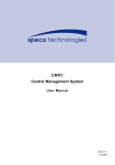
Five System Connection and Control
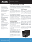
1. Rear Panel View
The rear panel connection sketch map is as below:
EXPLANATIONS:
- Direct current input
- Video output
Eight output connects. Users can connect to 8 monitors or other kind of video terminals.
- Monitor input
Connect to a monitor to make surveillance
- VCR input
Connect to VCR’s video output connector, and play back recorded files
- 4CH video output
Connect to VCR’s input connect to record files
- Sensor alarm and triggering signal input
DB25 connector
- RS232 / RS485 remote control connector
DB29 connector
- Video input
Maximum 8 channels camera video signal input or other standard video signals.
2. Alarm connector
13
QUAD-COL43 DUAL PAGE COLOUR QUAD USER’S MANUAL www.allthings.com.au
Explanations:
(1) 1 – 8: ALARM IN. mechanical alarm input, and voltage is adjustable. Connect to
sensor devices.
(2) 12: TRIGGER: trigger signal input, connect to VCR trigger output connector
(3) 14: ALARM N.C.: relay normal close end, connect to alarm
(4) 15: ALARM COM: relay public end, connect to alarm
(5) 16: ALARM N.O.: relay normal open end, connect to alarm
(6) 24: GND
(7) 25: VCC (+5V)
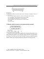
3. Remote control connector and communication protocol
5
1
9
6
DB9 connector:
2. TXD 3. RXD 5. GND
8. B
9. A
Notice: Pin 8 and 9 are used for RS422
Serial port’s remote control function enables users to control the quad through a PC or
ASCII communication terminal. The quad takes special commands as the key-pushing
commands in the front panel, and every command represents one or a combination of keys.
Any operation on the front panel can be done remotely, as serial port imitates key-pushing
operation. (Please refer to foregoing relevant menu instructions for choosing protocols)
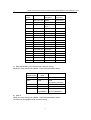
1) PTC 1 (ROBERT) (Fixed length character string)
Serial port setup: BAUD, n, 8,1(BAUD =1200,2400,4800,9600,19200)
14
QUAD-COL43 DUAL PAGE COLOUR QUAD USER’S MANUAL www.allthings.com.au
Command
Hex Number
Function
Description
(keyboard)
/AF
0x2F 0x41 0x46
MENU
FUNC+FULL
/PP
0x2F 0x50 0x50
/up arrow
/22
0x2F 0x32 0x32
2X2
(CHAR)
Note
/down
arrow
/33
0x2F 0x33 0x33
/ left arrow
/44
0x2F 0x34 0x34
/ right arrow
/LV
0x2F 0x4C 0x56
LIVE/ add
/TP
0x2F 0x54 0x50
VCR/ dec
/SL
0x2F 0x53 0x4C
/EXIT
/SQ
0x2F 0x53 0x51
AUTO/ENTER
/FZ
0x2F 0x46 0x5A
FULL
/01
0x2F 0x30 0x31
Cameras1
/02
0x2F 0x30 0x32
Cameras2
/03
0x2F 0x30 0x33
Cameras3
/04
0x2F 0x30 0x34
Cameras4
/05
0x2F 0x30 0x35
Cameras5
/06
0x2F 0x30 0x36
Cameras6
/07
0x2F 0x30 0x37
Cameras7
/08
0x2F 0x30 0x38
Cameras8
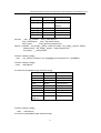
2) PTC 2 (ROBERT_EXT) (Fixed length character string)
Serial port setup: BAUD,n,8,1(BAUD =1200,2400,4800,9600,19200)
Transmitting
Sequence No.
Transmitting
value
Byte0
0x03
Fixed length
Byte1
0xaa
Quad
recognizing character
Byte2
0x01
Fixed length
Byte3
Device id
Quad address
Byte4~6
Refer to PTC
1 (ROBERT)
Same command
as PTC1(ROBERT)
Note
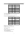
3) PTC 3
Serial port setup: BAUD,n,8,1(BAUD =1200,2400,4800,9600,19200)
PC sends off (changeable length character string)
15
QUAD-COL43 DUAL PAGE COLOUR QUAD USER’S MANUAL www.allthings.com.au
buf_232[0]
0xa0
Start mark
buf_232[1]
counter
Data length (n+1)
buf_232[2]
0x00~ff
MU8
address
buf_232[3]
function
Function code
device
buf_232[4]
buf_232[n]
buf_232[n+1]
check_sum
/function
0x01_key_function
0x02_ write eeprom
0x03_ read eeprom
0x04_ disp mode change
0x05_restart
0x06_general message query
eeprom command: buf_232[4]__change character length buf_232[5]__eeprom starting
address perch buf_232[6]__eeprom starting address low
buf_232[7]…..__change value
Function code(buf_232[3])
0x01
key_function command buf_232[4][5][6] is the same as PTC 1 (ROBERT)
Function code(buf_232[3])
0x02
write eeprom
PC sends off (changeable length character string)
Byte0
0xa0
Start mark
Byte1
counter
Data length (n+1)
Byte2
0x00~ff
MU8 device address
Byte3
0x02
Function code
Byte4
length
1~8 (maximum 8)
Byte5
high addr
0x00~0x07
Byte6
low addr
0x00~0xff
Byte n
Data n
0x00~0xff
Byte
Byte[n+1]
check_sum
Function code(buf_232[3])
0x03
read eeprom
PC receives (changeable length character string)
16
QUAD-COL43 DUAL PAGE COLOUR QUAD USER’S MANUAL www.allthings.com.au
Byte0
0xa0
Start mark
Byte1
counter
Data length(n+1)
Byte2
0x00~ff
MU8
address
Byte3
0x03
Function code
Byte4
length
1~8 (maximum 8)
Byte5
high addr
0x00~0x07
Byte6
low addr
0x00~0xff
Byte n
Data n
0x00~0xff
Byte
Byte[n+1]
device
check_sum
Function code(buf_232[3])
0x04
display mode
Note: cannot change mode when system is in playback mode
PC sends off (changeable length character string)
Byte0
0xa0
Start mark
Byte1
counter
Data length(n+1)
Byte2
0x00~ff
MU8
address
Byte3
0x04
Function code
Byte4
dumo_num
Byte5
buf_cam[0]
n
Byte6
buf_cam[1]
n
Byte
Byte[n+1]
check_sum
Byte4:dumo_num---- LFULL(00), L4(01)
buf_cam[n] n----0~7
PC receives same as common search results
Function code (buf_232[3])
0x05
restart
PC receives same as common search results
Function code(buf_232[3])
0x06 Common search result
PC receives(fixed length character string)
17
device
QUAD-COL43 DUAL PAGE COLOUR QUAD USER’S MANUAL www.allthings.com.au
Byte0
Byte1
Byte2
0xa0
0x0b
0x01~ff
Start mark
Data
length
MU8 device
address
Byte5:
Byte6:
Byte7:
Byte9:
Byte3
Byte11
check_su
m
errorcode
demo_num
menu_num
bit(1)—auto_flag , bit(0)—freeze_flag
byte check_sum(void)
{
byte i;
word wtemp = 0;
for(i=1; i<buf_232[1]; i++)
{
wtemp += buf_232[i];
}
wtemp = 0xffff - wtemp;
i = wtemp;
return (i);
}
4)
PTC 4
(PELCO) (Fixed length character string)
Baud rate
N
Parity bit
Data bit
None
8
Stop bit
Device address
1
0
Note N=1200,2400,4800,9600,19200
Protocol description
Protocol length 8 bits
Byte
1
Byte
2
Byte
3
Byte4
Byte
5
Byte6
Byte
7
Byte8
0xa0
Addr
0x00
0x07
0x00
Var
0xaf
checksum
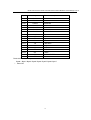
The 6th bit function description
18
QUAD-COL43 DUAL PAGE COLOUR QUAD USER’S MANUAL www.allthings.com.au
Byte6
key
0x01
Cam01
Cameras1
0x02
Cam02
Cameras2
0x03
Cam03
Cameras3
0x04
Cam04
Cameras4
0x05
Cam05
Cameras5
0x06
Cam06
Cameras6
0x07
Cam07
Cameras7
0x08
Cam08
Cameras8
0x11
/AF
MENU
0x12
/PP
/ up arrow
0x13
/22
2X2 / down arrow
0x14
/33
/ left arrow
0x15
/44
/ right arrow
0x16
/LV
LIVE / add
0x17
/TP
VCR / dec
Function description
0x18
/SL
/ EXIT
0x19
/SQ
AUTO / ENTER
0x1a
/FZ
FULL
th
The 8 bit function description
Byte8 = Byte1^ Byte2^ Byte3^ Byte4^ Byte5^ Byte6^ Byte7
^ Other OR
19