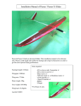
1
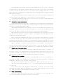
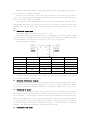
Fosc-21
Computer storage oscilloscope user's manual
z
Functions
· 2 channels input, synchronized display
· measure range automatically, 4 modes available
· input capture(trigger) function
· can set any channel as the source of capture(trigger) signal
· can set rising edge or falling edge to capture(trigger) signal
· adjustable capture(trigger) signal level
· save data in hard disk, system can call saved data automatically when it starts.
z
Technique parameters
· computer connection:USB
· signal input:BNC connection, with universal oscillograph probe
· maximum sampling:8 kHz * 1 / (4 kHz * 2)
· voltage:5 V
USB ports supply
· current:60 mA
· measurable frequency:0 Hz ----- 3 kHz
· DIV array:horizontal 16 DIV * vertical 10 DIV
· input impedance:1M Ω
· maximum voltage:0 --- 5 V
· error of voltage measurement: ±30mV
· adjustable range of time domain:10 mS/DIV-----10800 S/DIV
· error of time measurement:±0.1%
· capacity of data record and save:8388608 * 2
· the longest time of data record and save:93 hours
z
Chapter review
· advice for system configuration
· installation of hardware and drivers
· installation of software
· basic operation
· set display channels
· time domain adjustment
· signal capture(trigger)
· automatic range measurement
· signal wave lock and check
· method for key speedup
· data preservation
· extend of range span
· Waveform difference display
· Operation by mouse
· screenshot and print
· accessories
· software download and update
· Note
z
Advice for system configuration
Fosc-21 computer saving oscillograph (hereinafter oscillograph for short) and its software
supports Windows 2000 and Windows XP systems. We suggest the following configuration:
Windows XP system
CPU ≥ 1 GHz
Video card ≥ 32M , the driver must be installed properly
Memory ≥ 256M
Hard disk ≥ 100M
USB connection
z
Installation of hardware and drivers
Before install hardware and drivers, please copy all the files of CD into your hard disk.
You can save these files in any disk that has 100M free space. Please remember the saving route.
Oscillograph has three connections, they are:channel1 (1)、channel 2 (2)and USB connection,
see the following picture:
Connect one end of USB cable to the USB connection of oscillograph, and the other end to
computer. The light will on if the connection is right.
If this is the first time to run oscillograph, you need to run the "PL-2303 Driver
Installer.exe" to install the driver software. Note: After installation of driver software to
restart the computer.
z
Installation of software
In the file of Oscillograph's software, there are following files: “Focus Oscillograph
software xxx.exe” is oscillograph software; “Focus.mid” is background music; “Focus.osc” is data,
this file is produce after data has been saved; “CatchScreen.exe” is used for screenshot and print.
Oscillograph software is a harmless software and free installation. It will not install any
file in your system. You just need to run “Focus Oscillograph software xxx.exe” directly. It will
be more convenient if you create a shortcut on desktop. “xxx”is the version number of software,
please choose the latest edition as you can.
z
Basic operation
Please connect oscillograph after driver installation. Running oscillograph software, the
data will be empty and parameters are factory setting if you haven’t save data before. Otherwise,
data and status will be the same as it has been saved last time.
A:direction of music ON/OFF. Press [M]to turn on/off background music. The character of
“M”will change color when the music is on.
B:direction of data status. Press [F] to turn on/off saving function. Press [S] to save
immediately and press [L] to read at once.
C:press [F9] to turn on/off help window of operation.
D:show time domain parameters. The screen has 16 grids from left to right. the parameters
are the corresponding time of each grid. Press [Home] to gain time domain and [End] to minish
it.
E:show which channel is active. Press[space] to turn every channel to be active. If a channel
has been set to active, the range parameter of the channel will twinkle.
F:range parameters of CH1 to CH2 in turn. Screen has 10 grids from the top down. the parameter
refers to the range value of each grid.
G:press [F5] to open and close the display of current active channel. You can close unused
channels when measuring to increase sampling rate of channels. If only 1 channel is open, the
maximum sampling rate is 8 kHz. If more than 1 channels are open, these channels will share the
8 kHz sampling rate.
H:the activating channel trigger switch.
I:show the connect status of hardware. If oscillograph works properly, it will show the
type of oscillograph. E.g. “Fosc-21 x”
,“x” is the version number of hardware. If it shows “not
connected”, stop software first, connect oscillograph again, then run the software.
J:lock status of signal. press [Enter] to lock signal wave and unlock.
K:the value shows the range between vertical mark line Y2(“N”in the picture) and vertical
mark line Y1(“T”in the picture) when measure active channels.
L:measure mode. When vertical mark line Y2 is active, press [A] can transfer among 4 measure
modes. After this transfer, the information will keep 15 seconds on screen.
M1---M2:signal waves of CH1---CH2.
N:vertical mark line Y2. Press [Page Up] to activate Y1 and Y2 in turn. When Y2 is active,
press [Up] and [Down] to adjust vertical position and [A]to change measure modes.
O:show the capture(trigger) parameter of current active channels.
P:show the capture(trigger) direction of current active channels.
Q:switch state of difference channel display and the selected difference channel number.
R:horizontal mark line X2. Press [Page Down] to activate X1 and X2 in turn. When X2 is active,
press [Left] and [Right] key to adjust horizontal position.
S:horizontal mark line X1 and start point of capture (trigger). Press [Page Down] to activate
X1 and X2 in turn. When X1 is active, press [Left] and [Right] key to adjust horizontal position.
When capture (trigger) function is open, this position will be the start point of capture( trigger)
signal wave.
T:vertical mark line Y1. Press [Page Up] to activate Y1 and Y2 in turn. When Y1 is active,
press [Up] and [Down] to adjust vertical position.
U: the value shows the width between horizontal mark line X2( “R”in the picture) and
horizontal mark line X1( “S” in the picture) when measure active channels with the unit of 1/100
DIV.
W:mark of capture (trigger) level. It is the vertical start point of capture (trigger) signal
wave.
X:read data, press [L] to read at once.
Y:save data, Press [S] to save immediately.
Z:Shows the input voltage.
z
Set display channel
Press [space] to activate each channel in turn. “E”shows the number of active channel and
the range parameter of this channel twinkles. Press [F5] to open or close active channel. When
the channel is closed, “G”twinkles. If you want to set display channels, you need to press [space]
to activate channels in turn, and then press [F5] to open or close.
z
Time domain adjustment
Method: press [space] to activate target channel. Press [Home] to increase time domain and
[End] to minish it.
The longest time domain of oscillograph software is 10800 S/DIV and the shortest is 1 nS/DIV.
The longest time domain of Fosc-21 oscillograph is 10800 S/DIV, the proposed shortest time
domain is 10 mS/DIV.
Oscillograph has 3 different working mode according to the range of time domain:
10 mS/DIV-----50 mS/DIV, oscillograph displays signal wave frame by frame, this is the most
common mode.
100 mS/DIV-----4 S/DIV,oscillograph rolls signal wave from right to left. This mode is
convenient for observation.
4 S/DIV-----10800 S/DIV,oscillograph rolls signal wave from right to left and the wave can
be compressed or expanded. This is used to observe signal for a long time.
z
Signal capture (trigger)
Signal capture (trigger): oscillograph capture the discipline of signal change, then displays
signal with appointed characters on screen.
Setting method:Press [space] to activate target channel. Press [T] to start /stop capture
(trigger) function. The capture (trigger) signal source switches to the current active channel
as soon as the function works. Press [+/=] to increase capture (trigger) level and [-] to low
down it. Press [D] to change capture (trigger) direction, rising edge capture (trigger) or falling
edge capture (trigger).
“W”is the position mark of capture (trigger) level. “H” is the level parameter and direction.
capture (trigger) level parameter is a value relative to vertical baseline.
Oscillograph will display signal wave at the start point of capture (trigger)(horizontal
mark line X1) after it captures signal.
z
Automatic range measurement
Oscillograph can measure the voltage of signal waves on screen and there are 4 modes. Press
[Page Up] to activate vertical mark line Y2, and the movement status shows for the dotted line.
Press [A] to transfer among these 4 modes.
mode 0:Manual measurement. Press [Page Up] to activate vertical mark line Y1 and press [Up]
and [Down] to adjust tested position. Then press [Page Up] to activate vertical mark line Y2 and
press [Up] and [Down] to adjust vertical position. Voltage shows among movements.
Mode 1:measure peak value of active channel automatically. Press [Page Up] to activate
vertical mark line Y2. Press [A] switch to mode 1, the equipment can track signal wave crest
automatically and show the voltage.
Mode
2:Y1 manual,Y2 measure peak value of active channels. Press [Page Up] to activate
vertical mark line Y2. Press [A] switch to mode 2. Press [Page Up] to activate vertical mark line
Y1 and press [Up] and [Down] to adjust Y1 to tested position. Then press [Page Up] to activate
vertical mark line Y2 and Y2 can track signal wave crest automatically and show the voltage.
Mode
3:Y2 manual, Y1 measures lower peak value of active channels. press [Page Up] to
activate vertical mark line Y2. Press [A] switch to mode 3. press [Up] and [Down] to adjust Y2
to tested position. Y1 can track lower signal wave crest automatically and show the voltage.
z
Signal wave lock and check
Press [Enter] to lock signal wave and unlock. When signal wave locked, “J” twinkles, you
can press [<] and [>] to rolling screen to check signal waves. Press [Shift] and [Ctrl] can
accelerate the speed. After locking the signal waveform, the waveform can be adjusted by time
region prolong or compress, the max waveform can be observed is 93 hours.
z
Method for key speedup
When we make the operation of movement, adjustment and roll, we can use speedup key to
accelerate our speed. [Ctrl] and [Shift] are speedup keys, the operation method is to hold down
speedup key, then press other keys that can be speed up.
Keys that can be speed up by [Ctrl]:[Up] [Down] [Left] [Right] [F1] [F2] [F3] [F4] [<] [>].
Keys that can be speed up by [Shift]:[<] [>],[<] [>] can be speed up by [Ctrl] and [Shift]at
the same time.
Note :when we press [Ctrl] and [Shift] simultaneously to speed up,it may open entering
method and cause unable operation. We suggest you to press [Shift] then press [Ctrl]. You can
also change the hotkey of entering method in entering setting.
z
Data preservation
Press [F] to start /stop save function. Press [L] to read and [S] to save. The position of
“B”
will hint whether the read-write operation is successful.
Running oscillograph software, it will read saved data if the oscillograph connects properly.
You can press [L] to read data manually.
Data will be saved every 1 hour after saving function starts and the file name is
“Focus.osc”.Data file and oscillograph software are saved in the same route. Data preservation
won’t be successful without oscillograph.
If you want to create a redundant data file, you can create a folder first, then copy “Focus
Oscillograph software xxx.exe”
“Focus.mid”“Focus.osc”to the folder. If you want to check this
redundant file, you just need to run oscillograph software in the folder and press [L] to read
data.
z
Extend of range span
The maximum input span of BNC connection is 0 --- 5V.
When tested signal excess the measure range of oscillograph, you need to attenuate signal
with attenuator. You can made proper proportional attenuator according to your demand. The range
of oscillograph by the proportion of attenuator is the actual voltage value.
Product method of attenuator:
Attenuation rate
R1
R2
R3
R4
X2
470k
30k
1M
0
X3
610k
56k
470k
29k
X5
500k
300k
150k
100k
X10
750k
150k
100k
11k
X100
750k
240k
5k
5.1k
X1000
1M
0
1K
0
Attenuator and attenuator can mix to use. When they are mixed, the attenuation rate equals
to the product of every attenuation rate.
z
Waveform difference display
Fosc-21 Oscilloscope software suppose any double-channel difference signal display, press
[V], to open or close the difference signal display, press [C] to change the difference channel
A, press [B] to change the difference channel B, the difference signal display result = A-B.
z
Operation by mouse
For Fosc-21 Oscilloscope software. All the functions can be realized by mouse operation,
When the mouse moved to the operation of regional, Button will light, click the bottom by left
key of the mouse, to do the relative operation, when the bottom with left and right direction,
mouse click the middle part to execute switch type operation, mouse click the left and right part
to execute adjustment type operation. When lock the signal to check the waveform, press the left
key of mouse without loosen and move the mouse left or right, it will be rolling for viewing the
waveform . the faster for the moving, the faster for the rolling.
z
Screenshot and print
“CatchScreen.exe”is a software used to shot screen and print and it’s free installation.
Send a shortcut to desktop. We suggest putting this shortcut at the 4 corners of the desktop for
convenient click. Run “CatchScreen.exe” directly, dialog box of operating suggestion pops up.
Select the screen area, then double click to save picture to the clipboard of Windows.
You can edit and print pictures with image applications after you saved them, e.g. paint
software, Word , Excel , Photoshop ,etc.
There is also much professional screenshot software available.
z
Accessories
·the standard accessories in a suite are as following:
1-----------Fosc-21 oscillograph
* 1
2-----------USB cable * 1
3-----------BNC tie-ins * 2
4-----------CD * 1
z
Software download and update
We will update software and drivers regularly, please choose the latest version as you can.
In that way you can get stronger function and more stable performance. You can also download the
latest software and drivers on our website.
z
Note:
This manual is the translation from the Chinese version, if objection, please refer to the
Chinese manual.
Version number:Fosc-21-en 20090818
Copyright “ Shenzhen Fuyi Electronic Instrument Company Ltd. ”
Website: http://www.focussz.com
File Download page: http://www.focussz.com/fosc_21.rar