1
c 2012 Richard G. Otap
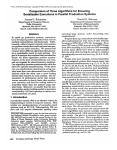
DEVELOPMENT OF A ROBOTIC TESTBED INFRASTRUCTURE
WITH DYNAMIC SERVICE DISCOVERY
BY
RICHARD G. OTAP
THESIS
Submitted in partial fulfillment of the requirements
for the degree of Master of Science in Electrical and Computer Engineering
in the Graduate College of the
University of Illinois at Urbana-Champaign, 2012
Urbana, Illinois
Adviser:
Professor Geir E. Dullerud
ABSTRACT
This thesis provides a blueprint for a component-based infrastructure incorporating dynamic service discovery for a robotic testbed. The infrastructure
consists of software using ZeroMQ as the transport layer for its speed and
ease of use. JSON and Protocol Buffers are used to implement messaging.
Finally, multicast DNS-SD is used, along with a custom software frontend
incorporating the chosen transport and messaging, to provide dynamic service discovery. The choice of these technologies allows the infrastructure to
stay simple and flexible for the programmer, while providing a full breadth
of features. The dynamic service discovery component allows the infrastructure to uniquely allow for services to come online and advertise themselves
on the network without a centralized broker. Services dynamically registered
are shown to be available in under one second to client services searching for
them on the network. This infrastructure adds standardization and adds new
functionality to the testbed, and provides a pre-designed software package to
simplify software development.
ii
To my parents, for their love and support.
iii
ACKNOWLEDGMENTS
I would like to thank all the members of the lab, without whom this project
would not have been possible: Daniel McKenna, for introducing me to the
lab systems and components; Seungho Lee, for all his controls work on the
hovercrafts; Qing Xu, for his Java work, and helping me test and develop
initial prototypes of the software; Yue Sun, for his work with the quadrotors;
Steve Granda, for his help with testing software, and with development of the
quadrotor software. Finally, I would like to thank my adviser, Geir Dullerud,
for his support and advice on this project, as well as the opportunity to work
in the lab.
iv
TABLE OF CONTENTS
CHAPTER 1 INTRODUCTION
1.1 HoTDeC Project . . . . .
1.2 Testbed Overview . . . . .
1.3 Motivation . . . . . . . . .
.
.
.
.
.
.
.
.
.
.
.
.
.
.
.
.
.
.
.
.
.
.
.
.
.
.
.
.
.
.
.
.
.
.
.
.
.
.
.
.
.
.
.
.
.
.
.
.
.
.
.
.
.
.
.
.
.
.
.
.
.
.
.
.
.
.
.
.
.
.
.
.
.
.
.
.
.
.
.
.
CHAPTER 2 DESIGN .
2.1 Requirements . .
2.2 Transport . . . .
2.3 Serialization . . .
2.4 Service Discovery
.
.
.
.
.
.
.
.
.
.
.
.
.
.
.
.
.
.
.
.
.
.
.
.
.
.
.
.
.
.
.
.
.
.
.
.
.
.
.
.
.
.
.
.
.
.
.
.
.
.
.
.
.
.
.
.
.
.
.
.
.
.
.
.
.
.
.
.
.
.
.
.
.
.
.
.
.
.
.
.
.
.
.
.
.
.
.
.
.
.
.
.
.
.
.
. 6
. 6
. 6
. 9
. 11
CHAPTER 3 IMPLEMENTATION
3.1 DirectoryD . . . . . . . . .
3.2 DataD . . . . . . . . . . . .
3.3 Vision . . . . . . . . . . . .
3.4 Controller . . . . . . . . . .
.
.
.
.
.
.
.
.
.
.
.
.
.
.
.
.
.
.
.
.
.
.
.
.
.
.
.
.
.
.
.
.
.
.
.
.
.
.
.
.
.
.
.
.
.
.
.
.
.
.
.
.
.
.
.
.
.
.
.
.
.
.
.
.
.
.
.
.
.
.
.
.
.
.
.
.
.
.
.
.
.
.
.
.
.
.
.
.
.
.
.
.
.
.
.
.
.
.
.
.
.
.
.
.
.
.
.
.
.
.
.
.
.
.
.
.
.
.
.
.
1
2
2
4
14
15
20
25
26
CHAPTER 4 ANALYSIS . . . . . . . . . . . . . . . . . . . . . . . . 28
4.1 Local Loopback Experiment . . . . . . . . . . . . . . . . . . . 28
4.2 Hardware Experiment . . . . . . . . . . . . . . . . . . . . . . 29
CHAPTER 5 CONCLUSION . . . . . . . . . . . . . . . . . . . . . . 31
APPENDIX A USER GUIDE .
A.1 Common Instructions for
A.2 DirectoryD . . . . . . .
A.3 DataD . . . . . . . . . .
A.4 Vision . . . . . . . . . .
A.5 Controller . . . . . . . .
APPENDIX B PROTOCOL
B.1 DirectoryD . . . . .
B.2 DataD . . . . . . . .
B.3 Vision . . . . . . . .
B.4 Controller . . . . . .
. .
All
. .
. .
. .
. .
. . . . . .
Programs
. . . . . .
. . . . . .
. . . . . .
. . . . . .
.
.
.
.
.
.
.
.
.
.
.
.
.
.
.
.
.
.
.
.
.
.
.
.
.
.
.
.
.
.
.
.
.
.
.
.
.
.
.
.
.
.
.
.
.
.
.
.
.
.
.
.
.
.
.
.
.
.
.
.
.
.
.
.
.
.
.
.
.
.
.
.
32
32
33
33
34
35
BUFFER LISTINGS
. . . . . . . . . . . .
. . . . . . . . . . . .
. . . . . . . . . . . .
. . . . . . . . . . . .
.
.
.
.
.
.
.
.
.
.
.
.
.
.
.
.
.
.
.
.
.
.
.
.
.
.
.
.
.
.
.
.
.
.
.
.
.
.
.
.
.
.
.
.
.
.
.
.
.
.
.
.
.
.
.
37
37
39
40
41
v
.
.
.
.
.
.
REFERENCES . . . . . . . . . . . . . . . . . . . . . . . . . . . . . . . 42
vi
CHAPTER 1
INTRODUCTION
The usage of component-based software design is not a new concept in programming [1]. Similar to object-oriented design, software can be split into
roughly independent components which communicate and interact with each
other to execute a larger functionality. The independence of the components
allows their errors to be localized, as well as simplifying the analysis of their
behaviors. It also allows for the re-use of components, as well as allowing different components to be split into separate programs and distributed across
a network. This thesis aims to provide such a component-based structure
for real-time robotics which will allow for the dynamic configuration and
discovery of physical robotic resources in real-time.
Component and monolithic models of a simple system are shown in figure
1.1. This is a system that might be used to control a simple robot. The
system has the capability to get user input, read sensor data, and perform a
calculation based off of that to control its motors. In the monolithic version,
everything is done in a single program: it consists of a single loop which loops
over each action in sequence. The component version is more interesting: it
consists of four separate programs, each encapsulating a single functionality,
which then communicate with each other as necessary.
The component version allows for more flexibility: each program can be
placed on the computer controlling the robot, or on a different computer on
the network — useful if processing power on the robot is limited. Likewise,
the behavior of each individual program becomes easier to analyze, as each
program has one simple function. It also allows parts of the system to be
exchanged in order to extend functionality — the controller program could
be replaced, for example, to change or improve the behavior of the system
without impacting the other programs.
1
main program
loop:
•
•
•
•
check for user input
get measurements
from sensors
recalculate
controller force
write output to
motors
controller program
loop:
sensor program
• check for messages
loop:
from user
• get measurements
• check for messages
from sensors
from sensor
• send sensor data to • recalculate
controller program
controller force
• send output to
motor program
user program
loop:
motor program
• wait for user input
loop:
• send user input to
• wait for messages
controller program
from controller
program
• write data to motors
Figure 1.1: A monolithic (left) and component (right) model of a simple
robotic system.
1.1 HoTDeC Project
The HoTDeC (HOvercraft Testbed for DEcentralized Control) project seeks
to provide a testbed for the implementation and testing of theories from
controls research. The use of hovercraft as the main vehicle in the testbed
ensures that active control is necessary to maintain the stability of the craft,
while also providing a controlled environment where the loss of control cannot
damage the vehicle. The testbed is in the process of adding new vehicles,
most recently quadrotor helicopters, with the goal of expanded testing in the
form of combined operations.
1.2 Testbed Overview
The testbed is made up of a few main hardware and software components.
There are several hovercraft vehicles, which can have their position tracked
by an overhead vision system running custom vision tracking software. Additionally, there are several quadrotors, which can be similarly tracked using a Kinect and custom tracking software. Either of these vehicles can be
controlled either autonomously using feedback control, or by a user via a
joystick. Both sets of vehicles communicate wirelessly with other comput-
2
ers and servers on the testbed network, which provide interfaces to sensors,
programs, and users on the Internet.
1.2.1 Hovercraft
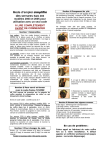
The hovercraft, shown in figure 1.2, consists of a foam body with five ducted
fan thrusters, one of which is used to generate lift; the other four provide directional control. Additionally, the vehicle contains a full suite of electronics
to provide it with control and communication capabilities. The main module consists of a Gumstix Overo Fire single-board computer (SBC), which
features an 800 MHz ARM processor and as 802.11 wireless communication capability. Low level control is provided by a TI F28335 digital signal
processor (DSP), which interfaces with the SBC via serial port. Connecting everything together is a custom designed vehicle controller board, which
handles logic level conversion as well as breaking out interfaces for common
devices, and bridging the connection between the DSP and the hovercraft
motors.
Figure 1.2: Hovercraft Version 2.2 Exploded View(left) and Exterior View (right)
Figure 1.2: Hovercraft exploded view (left) and exterior view (right).
Hovercraft Vehicle Electronics
The hovercraft vehicle contains a suite of electronic components that give it the control,
1.2.2
Quadrotor
communication,
and autonomy required for the testbed. Figure 1.3 shows a diagram of the
diÆerent electronic subsystems on the hovercraft [10].
The
quadrotors in use are Parrot AR.Drones [2]. The AR.Drone consists of
The
processing
power
of thewith
hovercraft
is supplied
by a small
computer
operating
a plastic
and foam
body
four rotors
(figure
1.3). SBC
It uses
a 400
MHz
at 800Mhz and running a Linux operating system. The SBC has the normal capabilities
of a desktop computer including the various serial, USB, and FireWire ports as well as a
3
wireless link using a PCMCIA card that provides an 802.11 wireless connection to a router.
In addition to the SBC, there is a Motorola HC912 MCU which is interfaced to the SBC
ARM processor, and also has 802.11 wireless capability. In terms of sensors,
it has: two onboard cameras, one on the front, the other on the bottom of the
vehicle; a 3-axis accelerometer; a 2-axis gyro; and an ultrasonic altimeter.
Figure 1.3: Parrot AR.Drone (left) and Microsoft Kinect (right).
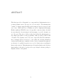
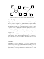
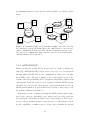
1.2.3 Vision system
The vision system consists of six Orange Micro Ibot firewire webcams mounted
2.6m above the testbed operational area, arranged in a two by three grid [3],
as seen in figure 1.4. The cameras are supported by three servers running
software to process the images, combine the data, and extract the coordinates of ground based vehicles. Due to the position of the cameras above the
floor, they cannot be used to track the quadrotors.
A Microsoft Kinect, seen in figure 1.3, is used to track anything that the
overhead cameras cannot. In addition to a regular camera, the Kinect provides a range camera. By combining data from both cameras, an accurate
estimate of the position of the vehicle can be obtained. Similar to the overhead system, the Kinect is connected to a server which processes the vision
and range data (using open source software [4]) and combines it into a coordinate position.
1.3 Motivation
The focus of this project is the development of open-source infrastructure
to link together all of these various software and hardware components. By
providing the testbed with a common infrastructure, common interfaces, and
4
Figure 1.4: Diagram of overhead vision system, detailing overlap of
adjacent cameras.
a unified programming model, development and testing of control software
can be streamlined and perhaps even made available to everyone, not just
those who understand network programming. Additionally, new, advanced
capabilities can be added which were previously unavailable, through the
addition of dynamic service discovery.
5
CHAPTER 2
DESIGN
The goal of the project is to develop an infrastructure for a robotic vehicular
testbed. Shakhimardanov et al. [5] introduce a protocol stack view (PSV)
model for discussing the design of such an infrastructure. In the PSV model,
such a system can be thought of in terms of layers: transportation, messaging,
interface definition, and service discovery. In this design, we simplify it, but
all four layers should still be identifiable.
2.1 Requirements
At minimum, the infrastructure should provide a standard communication
interface for programs running on a collection of networked vehicles. In addition, there should be a minimal reliance on libraries, both third party and
custom developed — it should exist mostly as a specification, with convenience bindings available, but not required, for multiple languages. It should
be inclusive of support for a variety of application types, including softrealtime applications and web applications. The specification itself should
also be as minimal as possible, while still ensuring that applications written
to the specification will be compatible.
Given these requirements, we can split up the development into three parts:
transport, serialization, and service discovery.
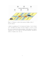
2.2 Transport
The transport layer represents the software layer responsible for defining
rules that govern the transfer of data from one location to another. It can
be thought of as a “pipe” (as in figure 2.1) that transports data from one
location to another. There are several considerations when it comes to the
6
Program
Object
Serialization Layer
Binary
Message
Transport Layer
Figure 2.1: The functions of the transport and serialization layers.
transport layer: a centralized or decentralized design, latency of message
transmission, and ease of programming.
2.2.1 Centralized
A system such as the Advanced Message Queuing Protocol (AMQP) provides
a centralized messaging design: messages are queued through a central broker
as seen in figure 2.2, which can provide certain reliability guarantees, such
as making sure a client receives a message [6]. The specification is complex,
and as such, is not amenable to porting to a large variety of languages.
2.2.2 Decentralized
A decentralized system, shown on the right in figure 2.2, does not have a
central broker, and is not able to provide the same reliability guarantees.
It does provide better latencies, however, and does not require any central
infrastructure to handle sending messages — nodes communicate directly
with each other.
A decentralized system better fits the needs of the system we are trying
to build. In terms of specifics, we choose to use ZeroMQ (ZMQ) [7] as our
transport and messaging layer. ZMQ provides a simple application programming interface (API) [8], with bindings to a variety of languages. It has also
been shown to work well in conjunction with a real-time kernel to reduce
latency jitter and peaks [9].
7
Client
Client
Client
Client
Message
Broker
Client
Client
Client
Client
Figure 2.2: Centralized (left) and decentralized messaging (right).
2.2.3 ZeroMQ
ZMQ provides an abstraction layer for communication which allows an application to abstract both interprocess communication and network communication under the same API. An application can connect to a local or remote
endpoint using the same code, specifying an appropriate address to connect
to. This allows us to be flexible in our design; we can move services from a
local node to a remote node for better performance without having to rewrite
code. Additionally, ZMQ provides added functionality over regular sockets,
such as connection retrying, message queueing, and receiving multipart messages whole [10].
ZMQ provides several different socket types, which support different messaging patterns. The two messaging patterns that will most commonly be
used in this framework will be Request-Reply and Publish-Subscribe (figure
2.3).
Request-Reply
Request-Reply provides a compatible pair of socket types, REQ and REP.
These provide a request-reply pattern, wherein every reply must be preceded
by a corresponding request. This is most commonly used for sending requests
where you expect a result, or requests where the application needs to verify
that its request was received.
8
XREP-XREQ
XREP and XREQ sockets are a variant on REP and REQ sockets provided
by ZMQ. While a REP socket must receive, process, and reply to a message
from a REQ socket before receiving a new request, an XREP socket can break
this lockstep and receive or reply to messages in any order. Additionally,
XREP/XREQ sockets can communicate with REP/REQ sockets. In this
way, it allows for the same pattern as Request-Reply, but in a more advanced,
asynchronous fashion.
Publish-Subscribe
Publish-Subscribe similarly has a pair of sockets associated with it, PUB and
SUB. A PUB socket is typically connected to one or more SUB sockets. The
PUB socket will “publish” messages, which are then received by all of the
connected SUB sockets, or “subscribers”. This makes it possible to broadcast
data, e.g. from a sensor, to a variety of receiving services.
REQ
PUB
REP
SUB
SUB
SUB
Figure 2.3: Request-Reply (left) and Publish-Subscribe (right) patterns.
2.3 Serialization
Serialization defines how an object is converted into a format that can be
stored or transmitted over the network through the transport layer (figure
2.1). There are a variety of common options for serialization, all of which
have strengths and weaknesses depending on the type of data being used,
the programming languages involved, and the desired application. For this
9
reason, we choose not to rigidly specify a single serialization format for use in
this framework, and will instead focus on two: JavaScript Object Notation
(JSON) and Protocol Buffers.
2.3.1 JSON
JSON is a simple, text-based data-interchange format [11]. The simplicity of
the format not only makes it easy for computers to parse, but also for humans
to read. The major drawback to JSON stems from its text-based nature as
well: the encoding of the data is not particularly space-efficient, especially
binary data: JSON has no specified way of encoding binary data. Doing so
would require first encoding the binary data into a secondary format which
contains only text characters, adding to the overhead and serialization time.
JSON is particularly suited to communication with web applications or
among dynamically typed languages. Many dynamic languages provide either libraries or inbuilt functionality to convert a JSON structure directly into
an object in the language, including Javascript, Ruby, and Python. JSON
communication from statically typed languages is not as simple; a statically
typed language requires knowledge of return types from methods at compile time, and is thus somewhat incompatible with the dynamic nature of
JSON. Using JSON is possible in a statically typed language, though more
cumbersome.
2.3.2 Protocol Buffers
Protocol Buffers are an efficient way of encoding data into messages automatically [12]. Unlike JSON, Protocol Buffers specify an efficient binary format
for encoding data as messages. Whereas JSON messages are free-form, Protocol Buffer messages must first be defined in a “proto” file, which is then
used to generate code to specifically encode the defined message. This makes
it easy to ensure that both the sending and receiving end are interpreting
the message in the same way; the proto file contains all of the necessary
information for the generation of code to interpret the data.
Prototyping an application or service is somewhat more difficult using
Protocol Buffers than JSON. As service names, fields, and data change, the
10
proto file must be updated and the code regenerated, as well as all the calling
code updated to reflect changes in the generated code. However, usage of
Protocol Buffers in a statically typed language is still generally easier than the
usage of JSON; the Protocol Buffer compiler takes care of all of the parsing
and data type assignment, which must be done at least semi-manually for
JSON. Even if a library is used to parse the JSON structure, a program
writer must still walk and assign types to the JSON fields manually.
2.4 Service Discovery
Service discovery defines functionality by which an application can find other
applications on the network which provide the services that it needs access
to. Again, we have both centralized and decentralized options for service
discovery.
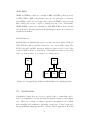
2.4.1 Centralized
A centralized discovery service is simplest: all applications communicate with
a centralized service, with which they can register their network address
and availability for all other applications on the network to see (figure 2.4).
However, if the centralized service fails, all applications go offline as they are
unable to discover and communicate with other applications.
2.4.2 Decentralized
A decentralized discovery service solves this by running a discovery service
on each node (figure 2.4). The services running on the node communicate
with the local discovery service. These discovery services then communicate
with each other, sharing the availability of all of the services on each local
node. If one node goes down, all of the other nodes can stay available and
continue to advertise their services.
As we want to minimize the usage of static infrastructure, we choose the
decentralized service discovery approach. Multicast DNS Service Discovery
(DNS-SD) [13] provides decentralized service discovery using standard DNS
11
programming interfaces, and is already widely available on a variety of platforms.
Client
Client
Discovery
Service
Client
Discovery
Service
Client
Discovery
Service
Client
Discovery
Service
Client
Client
Figure 2.4: Centralized (left) and decentralized (right) service discovery. In
the centralized version, all clients talk to the central server to discover and
enable communication with each other. In the decentralized version, each
discovery node communicates with other discovery nodes and with clients,
enabling clients to find each other.
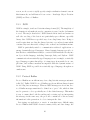
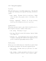
2.4.3 mDNS/DNS-SD
Known as Bonjour on Mac OS X and provided by Avahi on Linux systems [14], mDNS/DNS-SD provides service discovery on a local network
through multicast DNS. Due to the communication being done over multicast DNS, service discovery is limited to the local network; however, the
benefits of the wide availability and broad system compatibility of this system
outweigh this drawback. Services can be registered with the mDNS system,
and then discovered by any other system on the network that also has an
mDNS system installed. A typical interaction between a client, service, and
the system is illustrated in figure 2.5.
Registering a service requires providing the mDNS system with a name,
service type, and port. Optionally, “text” entries can be provided, which are
key-value pairs of metadata about the service being registered. These can be
used by other programs looking for a specific service to differentiate between
specific capabilities of similar services. Service type identifies the general
12
category of the service being provided; for example, there may be different
service types for data from a camera sensor or a joystick.
Since we want all services to communicate through ZMQ and a suitable
serialization format, we need to introduce a service which wraps and simplifies
the interface provided by the system. We call this the directoryd service,
and it is described in the next chapter.
a
DNS-SD daemon
ZeroMQ IPC Socket
Server PC
b
Server program
d
ZMQ Socket
Multicast DNS
c
DNS-SD daemon
ZeroMQ IPC Socket
Client program
Client PC
Figure 2.5: Client and server in a service discovery scenario. At (a), a
server program registers itself with the discovery service. The discovery
service communicates with other nodes (b). A client program can then talk
to its local discovery service (c) to find information about the server
program. Finally, the client program has the address of the server program,
and can open communication with it (c).
13
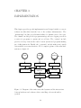
CHAPTER 3
IMPLEMENTATION
This chapter provides specific implementation and design details for concrete
software modules that form the base of the software infrastructure. The
“directoryd” module provides functionality for dynamic service discovery.
The “datad” module provides program message and error logging, as well as
a service for programs to capture and record data. The “vision” module
provides a bridge between the testbed vision system and programs making
use of this framework. Finally, the “joystick” module makes raw joystick
data available as a network service. For a complete picture of the networked
system, see figure 3.1.
Joystick
Camera
Database
Joystick Server
Vision Server
Parameter Storage
Reference Generator
Controller
+
Kalman Filter
Data Logger
Serial Server
Event Logger
Hardware
Figure 3.1: Diagram of the entire networked system and the interactions
between hardware and software when controlling a hovercraft with a
joystick.
14
Listings of the Protocol Buffer structures implementing message types for
each program appearing in this chapter are provided in Appendix B.
3.1 DirectoryD
The directoryd program provides service directory support, bridging mDNS
to the interfaces described in the framework specification. There should
be one instance of directoryd running on each node, and each node will
communicate, over multicast, with other nodes on the local network to share
services.
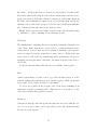
Interfacing with directoryd is described below, as a series of request messages. A “register” message is sent to register a service; a “unregister” message will remove the service. A “find” message can be used by client programs to locate services. One reply message is sent for every request message
received.
Services wishing to register themselves must maintain communication with
the directoryd service during the duration of their registration via heartbeat messages. Any of the previously mentioned message types count as
a heartbeat message; or, an empty message may be sent. These heartbeat
messages must be received by the directoryd service once per second, or
the service will be disconnected and removed from the directory. Services
will not be notified if they have been disconnected in this way. Figure 3.2
outlines this behavior in the form of a state diagram.
Clients that just wish to use the service location functionality do not need
to send a heartbeat message, as there is no state stored on the directoryd
service after the conclusion of the find request.
A service wishing to make use of directoryd should connect through a
ZMQ REQ socket to the inter-process communication (IPC) address at the
location ipc:///tmp/directoryd. As with all ZMQ REQ sockets, after
sending a request, a client must wait for a reply before continuing to make
requests.
15
register
heartbeat
register
initial
state
no messages
for > 1s
unregister last
remaining service
active
service
unregister
Figure 3.2: A state diagram for registering services. Registering a service
puts it into the active state. The active state is maintained by sending a
heartbeat or performing any other type of action at least once per second.
3.1.1 Implementation Details
The program begins by setting up a ZMQ XREP socket at the location
/tmp/directoryd. This is an IPC socket, and thus can only be accessed
locally from by other programs running on the same machine.
Next, the program sets up to interface with the mDNS/DNS-SD implementation. This runs in a separate background thread, and is responsible for
actually registering services on the network and receiving information about
new services on the network. New services advertised on the network are
cached locally to enable find requests from clients to be processed quickly.
Next is the main event loop, which receives and processes incoming messages.
In the first part of the loop, the program extracts the identity header from
the message. This is used later on in the program when generating and
sending a response to ensure that the response message is routed back to the
correct host. It is also used to keep track of which host the particular request
is coming from in order to manage service lifetimes and timeouts.
Finally, the request is dispatched depending on the content of the message:
register, unregister, find, or heartbeat.
Register
First, a new service group is created and all of the requested services are
added to this group. The identity header is used to establish the identity of
16
the client — if this is the first set of services being registered by this client,
then a new entry for the client is created in the datastructure, and the service
group is stored there. Likewise, a timer is configured to test for timeouts from
the client, and is initialized to expire in one second. If the client already has
existing services, this service group is added into the datastructure with the
rest of them, and the timeouts for the client are reset.
Finally, if the request was successful, a reply is sent to the client indicating
so. Otherwise, a reply containing an error message is sent.
Unregister
The datastructure containing all services is searched using the identity header
of the client. If the client has no active services, or if the particular service
being removed does not exist, an error is returned. Otherwise, the requested
service is removed from the client’s list of active services. If this is the last
active service for the client, the client’s entry in the datastructure is removed,
including removing the timer. Otherwise, the timer is updated and reset to
one second.
A reply is sent indicating either the success or failure of the request.
Find
A find request filters a locally cached copy of all advertised services on the
network against the parameters provided in the request, which can include
service type, service name, and service text entries.
No errors are possible in the request, aside from errors stemming from
malformed requests or missing fields. Timeouts are not updated for any
active services when this request is received.
Heartbeat
A heartbeat message will only update the timeouts associated with the service. No errors are possible, and a reply will be sent to the client indicating
the success of the request.
17
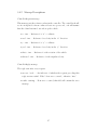
3.1.2 Message Descriptions
Register message
A register message should be sent by a service that is registering its location.
The service must provide a name, as well as a type and a port. A service may
register more than one type and port under the same name — this is useful
for programs which provide data in multiple formats, or for a multifunctional
program.
Upon success, a reply will be sent with success set to true. If the request
fails for any reason, a reply with success set to false will be returned, with
a result string describing the error.
• name : string — The name of the service. This must be unique across
all registered services.
• location : Location[] — One or more location objects (defined below).
A service must register itself as having at least one location, but may
provide several. A service sending a register message is assumed to be
available locally, so it need only provide a port and service type.
• txt : TxtField[] — Text fields for the service. This consists of one
or more TxtField objects, and is used to provide metadata about the
service to allow clients to differentiate between similar services. These
are optional, and the service may provide zero or more text fields.
TxtField message
A key-value pair providing metadata about a service.
• key : string — The key, describing the type of information stored in
the value.
• value : string — A descriptive value.
Location message
A location message describes the location of a service inside of a register
request.
18
• type : string — A type describes the general category of the service.
For example, a webcam providing a live video may be registered as
type “webcam”.
• port : int — The port where the service may be found.
Unregister message
A message to unregister a previously registered service. Success will result in
a reply with success set to true. If the request fails, a reply with success
set to false will be returned, with a result string describing the error.
Contains a single field.
• name : string — The name of the service to unregister. All services
locally registered with a matching name are unregistered.
Find message
A request to locate a service. Services may be matched directly by name,
or they may be searched for more generally, by type. Services may also be
filtered by the contents of their text field.
Upon success, a reply will be sent with success set to true. Additionally,
the message will contain the locations of zero or more matching services :
zero matches is considered a success, not an error. If the request fails for any
reason, a reply with success set to false will be returned, with a result
string describing the error.
• type : string — The type of service to search for, as described above
in the register message.
• name : string — An optional name to find an exactly- matching
service.
• txt : TxtField[] — An optional set of text fields to match against
available services.
19
Service reply message
This is the reply message sent in response to all requests received. Only the
success field is required : the rest are optional, depending on conditions. The
result field is filled if the success field is false. The findresult field is filled if
this is a response to a find result and if the success field is true.
• success : bool — The success or failure status of the request matching
this reply.
• result : string — A result message; if there was any failure, the error
message is contained here.
• findresult : FindResult[] — If this is a reply to a find request, any
services found are contained here.
FindResult message
This message is a field of the service reply message, and is included as a reply
to find requests.
• location — Location[] : The location of the service that matched the
find request.
• txt — TxtField[] : The text field of the service matching the request
— this can be used to additionally filter or distinguish between services
if multiples are found.
3.2 DataD
The datad service represents the logging portion of the infrastructure. It
can be used for both logging regular program messages and errors, for logging and recording program data (figure 3.3), and for storing and retrieving
configuration values and parameters.
The first service, logging of program messages and errors, is registered in
directoryd as type logger. The service sits on a ZMQ SUB socket. A
client wishing to utilize the service should simply connect to the port and
address returned from directoryd. No other configuration is required after
20
that — simply sending “Log” messages (described below) to the service will
begin logging and perform any necessary internal configuration. Aside from
log strings, these messages also contain optional log “level” and timestamp
fields. The log level can be used to describe the severity of the message. The
timestamp can be provided in case the precise time of occurence of the event
being logged is required — if not provided, a timestamp will be filled in by
the logger.
Next, the program data logging functionality is registered as type data,
and similarly sits on a ZMQ SUB socket. The usage is identical to that
of the first service, except that “DataLog” messages should be used instead.
Timestamps are not saved by the logger for data logging — if they are needed,
they should be saved manually, either as another log, or embedded as part of
the data portion. An example of this behavior can be seen in figure 3.3. In
the figure, a server program logs a data triplet at certain time intervals, which
can then be accessed by a client program. The server program is responsible
for filling and encoding all parts of the triplet, and the client must be aware
of the encoding used in order to make use of the data.
Server Program
Database
log( { time, position, velocity } );
Client Program
get( position, t1 … tn );
{ t1, p1, v1 }
{ t2, p2, v2 }
{ t3, p3, v3 }
{ t4, p4, v4 }
{ t5, p5, v5 }
{ t6, p6, v6 }
{ t7, p7, v7 }
{ t8, p8, v8 }
{ t9, p9, v9 }
Figure 3.3: A sample flow of a client and server making use of the data
logging functionality.
The final functionality is of type kv-store, and provides storage of configuration objects containing sets of key-value parameters. This is the most
complicated of the three services provided. It uses a ZMQ REP socket, and
as such, a client should connect using a ZMQ REQ socket. It takes “HSet”
and “HGet” messages; HSet messages are used to set key-value pairs in an
object, and HGet will retrieve them. Every HSet and HGet message sent
21
will get a response of type HReply — these will indicate whether or not any
errors occurred in processing the request, and in the case of HGet, will also
contain the requested data.
3.2.1 Implementation Details
The program begins by setting up three sockets; logger, data, and kv- store.
The former two are ZMQ SUB sockets, and the latter a REP socket. These
are registered with the directoryd service, and a timer is set up to send a
heartbeat message to the service once per second. A connection is established
with a back-end database program, which will be used to store and retrieve
anything sent.
In the main loop, the program polls the above sockets and receives new
messages.
Logger
The logger receives the message and checks the optional fields. If the timestamp field is not provided, the current time is checked and used as the timestamp for the log message. All of the log messages sent are tagged with the
timestamp, and then are inserted into the database. The database will keep
the last ten-thousand messages logged.
Data
For the data logging functionality, log messages are simply received and
logged into the database without further processing. Timestamps or any
other metadata should be added by the client program before being sent to
the logger.
KV-Store
An HGet request will cause the program to fetch the requested data from
the database and format it into a response message to be sent to the client.
An HSet request will cause it to set the appropriate fields in the database to
the values provided in the body of the request.
22
3.2.2 Message Descriptions
Log message
This is the message type to use with the logger service. The name field
is required, and each message only requires the data string; other fields are
optional.
• name : string — The name of the log to log the data to. Usually
refers to the name of the program or service, or the instance of the
program.
• messages : LogString[] — Messages to log. At least one message
should be provided, though it is not an error to provide zero.
LogString message
This message represents a single log entry. Only the data field needs to be
filled, though the others may be useful in certain scenarios.
• data : string — The string to be logged.
• level : int — The level of severity of the log message. Optional, defaults
to the “INFO” level.
• timestamp : int — A 64-bit timestamp for the log message. This field
is optional : a timestamp will be filled in by the logging service if not
provided. Useful when logging multiple messages together.
DataLog message
Message type for use with the data service. Both fields are required, though
the content and representation of the data field is application-specific.
• name : string — The name of the log to log the data to. See “name”
in “Log message”.
• data : string — A string representation of the data to be logged.
Numerical data should be converted to a unicode string for logging.
23
HSet message
This message type is used with the kv-store service for setting the values of
a configuration object. An HReply message will be returned with the success
status of the set operation.
• key : string — The object for which key-value pairs will be set. Can
refer to a program name, or to another general cluster of values.
• values : HValue[] — One or more key-value pairs to be logged.
HGet message
This message type is the counterpart to the HSet message, and is used with
the kv-store service for retrieving values from a configuration object. An
HReply message will be returned with the success status of the operation
and, upon success, will also contain the values of the fields requested.
• key : string — The object from which to retrieve the key-value pair.
• fields : string[] — The fields from which values will be returned.
HValue message
This message type is embedded in HSet messages and contains a single keyvalue pair from an object.
• field : string — The “key” in each object.
• value : string — The value that corresponds to the above key.
HReply message
This is a reply message from the kv-store service, returning status of either
a HSet or HGet request, and optionally, a result string in the case of an error,
or values for a HGet request.
• success : bool — An indicator of whether the request preceding this
reply was successful. “False” if an error occurred, otherwise “true”.
24
• result : string — If an error occurred, this field will contain the error
message.
• values : string[] — If this is in reply to an HGet request, this field
will contain one or more values corresponding to the number of fields
requested.
3.3 Vision
This “vision” service provides a bridge between the testbed vision system
and programs making use of this framework.
Interfacing with this service is simple; it uses a single ZMQ PUB socket
which broadcasts the position of every hovercraft that it detects in the form
of the “vision” message, defined below.
3.3.1 Implementation Details
Functionally, the vision program is simple. It opens a ZMQ PUB socket
and registers it with directoryd. Then, it connects to the testbed overhead
vision system and begins receiving messages. In a loop, it processes these
messages, reformatting them into a Protocol Buffer message, which it packs
and broadcasts over the PUB socket.
3.3.2 Message Descriptions
Vision message
The message format for the hovercraft position. One message is sent out for
each hovercraft detected.
• k : int — The number of the hovercraft top that was detected.
• x : int — The “x” coordinate.
• y : int — The “y” coordinate.
• theta : int — The rotation of the vehicle.
25
3.4 Controller
This is a linear-quadratic regulator (LQR) controller implementation that
utilizes the vision and logging infrastructure detailed above. It finds and
connects to the vision service to track the position of the hovercraft it is
providing control for, and must be provided with values for the reference
position that the control values should be calculated for. Only a single client
may be sending these values to the controller at a time — the client assumes
control upon sending its first successful request. If a client sends a request
while another client is already in control, an error reply will be sent back. In
order to maintain control, a client must continually send updated reference
messages. If a client does not maintain communication, another client will
be able to assert control of the controller.
3.4.1 Implementation Details
The controller implementation uses the logging functionality detailed above;
the first thing it does is set up a connection to the logger. Next, it uses
directoryd to find and connect to the vision service. After setup is complete, the controller registers itself as a service.
In a loop, the program polls for data from both the vision socket and its
own socket. If it gets a reference object from a client, it sets up a new instance of an LQR controller and Kalman filter using the most recent location
received from the vision socket. If this is successful, the client now controls
the program, and will be able to send updates to the reference position in
the program.
If the program gets a reference from a client that is not currently controlling
the program, the request fails and the program replies with an error. If the
program does not receive an update from the controlling client in over one
second, the client is assumed to have disconnected, and the controller will
stop the vehicle.
At every update received from the vision socket, the program will update
and recalculate the state estimates from the Kalman filter and the state and
output of the LQR controller.
26
3.4.2 Message Descriptions
ControllerRequest message
This message sets the reference values in the controller. The controller should
receive an updated reference value at least once per second, or it will assume
that the client has timed out and stop the vehicle.
• x : int — Reference for “x” coordinate.
• xvel : int — Reference for velocity in the “x” direction.
• y : int — Reference for “y” coordinate.
• yvel : int — Reference for velocity in the “y” direction.
• theta : int — Reference for the rotation of the vehicle.
• thetavel : int — Reference for the angular velocity.
ControllerReply message
The reply sent after every request.
• success : bool — An indicator of whether the request preceding this
reply was successful. “False” if an error occurred, otherwise “true”.
• result : string — If an error occurred, this field will contain the error
message.
27
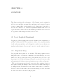
CHAPTER 4
ANALYSIS
This chapter analyzes the performance of the dynamic service registration
and discovery capability, in terms of how much time can be expected between
a service coming online on the network, and a client service being able to
discover and connect to it. The first experiment analyzes this in a local
loopback scenario, whereas the second analyzes performance in a more reallife experiment with multiple machines and real data.
4.1 Local Loopback Experiment
The purpose of this experiment is to test the dynamic service registration capability of the framework. This experiment consists of two programs running
locally on the same machine, and is designed to test the best-case latency one
might get when trying to discover and connect to a newly registered service.
4.1.1 Experiment Setup
Two programs run together on one machine. The first program creates a
ZMQ PUB socket, over which it continually broadcasts messages, one every
millisecond. The program registers its socket with the directory service, and
then starts to broadcast the messages. Every 10 seconds, it closes the socket
and unregisters it; it then creates and registers a new socket, and repeats.
The second program searches and connects to these registered services,
and begins receiving the messages. As soon as it detects that it has stopped
receiving new data, it searches for a new version of the service to connect to.
Then, we can record the time between the last message received and when
the new service has been found by the program.
28
4.1.2 Results
As a result of this, we can calculate that the delay between a service being
registered and discovered is approximately 972 milliseconds. Even locally,
there is a certain amount of time between when the service is registered and
when it becomes available and visible to other programs.
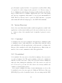
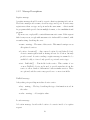
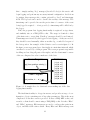
4.2 Hardware Experiment
The setup for this experiment is similar in terms of software, except live data
from the vision service is used. The data from the vision system is split into
four quadrants (figure 4.1), and each quadrant is assigned to a be broadcast
by a separate service, to emulate different, independent camera services.
vision-1
vision-2
hovercraft
vision-3
vision-4
Figure 4.1: For the hardware experiment, the floor is split up into four
quadrants with virtual cameras.
For each of the services, the text data contains information about the
hovercraft that it sees. The task of the client program is to find the service
which sees the hovercraft, connect to it, and receive messages from it. As the
hovercraft is moved across the room, the program must find and reconnect
to the appropriate service.
29
4.2.1 Results
From this experiment, we can calculate a delay value from a more realistic
use case. The delay that we get is similar to the local service loopback delay,
977 milliseconds. The majority of the delay seems to be associated with the
rebroadcast delay in the mDNS/DNS-SD service itself rather than network
delay.
30
CHAPTER 5
CONCLUSION
The new infrastructure described provides a definitive increase in the capabilities of the testbed. It adds a level standardization that was previously
lacking, while still leaving enough flexibility so as not to hinder novel design
choices, as well as easing the development of future modules to support the
testbed.
The new system also provides the additional benefit of allowing for dynamically registered and discovered services on the network, adding generic
support for a functionality that was not easily added to the testbed before.
This opens up new types of experiments to the testbed, as well as making it
easier to implement standard experiments.
By providing a number of pre-designed and developed software modules,
the testbed also allows the focus to be moved from redeveloping these basic pieces of infrastructure, to the implementation of the theories which the
testbed was built to test, thus making the testbed more accessible to everyone. In the future, more modules can be added to simplify the programming
model even more, to the point of perhaps making it easy for non-programmers
to program and control the vehicles in the testbed.
31
APPENDIX A
USER GUIDE
Chapter 2 described how the software works, internally, and the design decisions that went into it. This appendix is intended as a user manual — how
to build and run the software, and any special considerations or prerequisites
that are necessary.
A.1 Common Instructions for All Programs
A.1.1 Build and Installation
The build instructions are identical for each program; CMake is used to
generate build files. Make sure you are in the program’s directory. To build
using the recommended configuration:
mkdir build
cd build
cmake ..
make
make install will install the program and development files in /usr/local.
A.1.2 Common Dependencies
In addition, most programs have a minimum set of requirements in common
with each other:
• ZeroMQ 2.1.1 or newer
• Protocol Buffers
32
• GCC 2.6 or newer (for C++11 support)
• CMake
A.2 DirectoryD
This is a software package that provides service directory support for the
testbed. It consists of the server program, as well as client libraries in C++,
and protocol buffer files for developing new clients. Installing the program
will install the full package, including client libraries.
A.2.1 Additional Dependencies
• Avahi
A.2.2 Usage
directoryd [-dh]
-d
launch as daemon
-h
help
There are no special parameters, aside from launching the program as a
daemon. Care should be taken to ensure that only a single instance of the
program is launched at a time; the file /tmp/directoryd is used for IPC
communication, and is not locked. Additionally, you should make sure that
the aforementioned file is writable by this program, as well as the rest of
these programs.
The client library is provided in the ddclient directory; query.hpp provides find functionality, and register.hpp provides registration functionality. Example programs are also available.
A.3 DataD
This program provides a logging service for the testbed. It uses a Redis
database on the backend for storing data. Client libraries are also provided
33
for C++.
A.3.1 Additional Dependencies
• Redis C++ Client library
• directoryd client library. See the directoryd section (Section A.2).
A.3.2 Usage
datad -r <address> [-pdh]
-r redis host to connect to
-p port to bind to
-d launch as daemon
-h help
There needs to be an instance of Redis running to use this program. The
address should be provided as a parameter. Only one instance of this program
needs to be running on the network at a time, though more will not break
anything.
The client library is provided via data.h; an example program is also
available.
A.4 Vision
The vision program provides an interface to the overhead vision system in
the lab. It receives data from the vision system and reformats it into protocol
buffer messages which are then rebroadcast.
A.4.1 Additional Dependencies
• directoryd client library. See the directoryd section (Section A.2).
34
A.4.2 Usage
vision
-s
-p
-d
-h
[-dh] [-s <address>] [-p <port]
source address to connect to
port to bind to
launch as daemon
help
The source address specifies the address of the overhead vision system
server. The overhead vision server should be running in order to make use
of the functionality provided by this program. Launching the program as a
daemon allows it to run in the background, as a daemon.
A.5 Controller
This is an LQR controller implementation for the hovercraft that utilizes the
above infrastructure. It advertises itself on the network, gets vision data
from the vision program, and logs errors and information to the database.
A.5.1 Additional Dependencies
• directoryd client library. See the directoryd section (Section A.2).
• vision client library. See the vision section (Section A.4).
• datad client library. See the datad section (Section A.3).
A.5.2 Usage
controller++ -n <number> [-p port] [-adh]
-n
hotdec number (required)
-p
port to bind to (default: 12345)
-d
launch as daemon
-h
help
The hovercraft number for the craft to be controlled must be provided.
The program should automatically locate all resources necessary. Errors will
35
be logged (so long as directoryd and datad are running) and can be used for
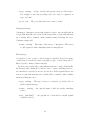
diagnosis in case of failure.
Parameters for both the controller and Kalman filter are in controller.cc
and can be modified as necessary.
36
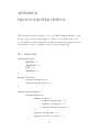
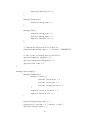
APPENDIX B
PROTOCOL BUFFER LISTINGS
This appendix includes listings of Protocol Buffer implementations of the
message types described in Chapter 2. These are verbatim source code —
for descriptions of each of the fields, see the aforementioned chapter. For an
introduction to protocol buffers, see the developer’s guide [12].
B.1 DirectoryD
enum RequestType {
REGISTER = 1;
UNREGISTER = 2;
FIND = 3;
HEARTBEAT = 4;
}
message TxtField {
required string key = 1;
required string value = 2;
}
message ServiceRequest {
message Register {
message Location {
required string type = 1;
optional int32 port = 2;
optional string resource = 3;
}
required string name = 1;
repeated Location location = 2;
37
repeated TxtField txt = 3;
}
message Unregister {
required string name = 1;
}
message Find {
required string type = 1;
optional string name = 2;
repeated TxtField txt = 3;
}
// Identifies which field is filled in.
required RequestType type = 1 [ default = HEARTBEAT ];
// One of the following may be filled in.
optional Register register = 2;
optional Unregister unregister = 3;
optional Find find = 4;
}
message ServiceReply {
message FindResult {
message Location {
optional string host = 1;
optional int32 port = 2;
optional string resource = 3;
}
required Location location = 1;
repeated TxtField txt = 2;
}
required RequestType type = 1;
required bool success = 2 [ default = true ];
optional string result = 3;
38
repeated FindResult findresult = 4;
}
B.2 DataD
message Log {
enum Level {
DEBUG = 0;
INFO = 1;
WARN = 2;
ERROR = 3;
FATAL = 4;
}
message Message {
required string data = 1;
optional Level level = 2 [default = INFO];
optional int64 timestamp = 3;
}
required string name = 1;
repeated Message messages = 2;
}
message DataLog {
required string name = 1;
repeated string data = 2;
}
message HValue {
required string field = 1;
required string value = 2;
}
message HRequest {
39
enum Type {
SET = 0;
GET = 1;
}
message HSet {
required string key = 1;
repeated HValue values = 2;
}
message HGet {
required string key = 1;
repeated string fields = 2;
}
required Type type = 1;
optional HSet set = 2;
optional HGet get = 3;
}
message HReply {
required bool success = 1;
optional string result = 2;
repeated string values = 3;
}
B.3 Vision
message Vision {
message Position
required
required
required
required
}
{
uint32
uint32
uint32
uint32
k = 1;
x = 2;
y = 3;
theta = 4;
40
repeated Position pos = 1;
}
B.4 Controller
message ControllerReq {
required double
required double
required double
required double
required double
required double
}
x = 1;
xvel = 2;
y = 3;
yvel = 4;
theta = 5;
thetavel = 6;
message ControllerRep {
required bool success = 1;
optional string result = 2;
}
41
REFERENCES
[1] C. Szyperski, D. Gruntz, and S. Murer, Component Software: Beyond
Object-Oriented Programming. Addison-Wesley Professional, 2002.
[2] “Parrot AR.Drone — technologies,” 2012. [Online]. Available:
http://ardrone.parrot.com/parrot-ar-drone/en/technologies
[3] A. Fulford, “Networked vision system for autonomous vehicle control,”
M.S. thesis, University of Illinois at Urbana-Champaign, 2005.
[4] “Openkinect project,” 2012. [Online]. Available: http://openkinect.
org/wiki/Main Page
[5] A. Shakhimardanov, N. Hochgeschwender, M. Reckhaus, and G. Kraetzschmar, “Analysis of software connectors in robotics,” in Intelligent
Robots and Systems (IROS), 2011 IEEE/RSJ International Conference
on, 2011, pp. 1030–1035.
[6] M. Klishin, “AMQP 0-9-1 model explained,” 2012. [Online]. Available:
http://www.rabbitmq.com/tutorials/amqp-concepts.html
[7] “The intelligent transport layer — zeromq,” 2012. [Online]. Available:
http://www.zeromq.org/
[8] “ØMQ/2.2.0 API reference,”
//api.zeromq.org/2-2: start
2012. [Online]. Available:
http:
[9] “Tests on linux real-time kernel,” White Paper. [Online]. Available:
http://www.zeromq.org/results:rt-tests-v031
[10] P. Hintjens, “ØMQ – the guide,”
http://zguide.zeromq.org/page:all
2012. [Online]. Available:
[11] “JSON,” 2012. [Online]. Available: http://www.json.org/
[12] “The Protocol Buffers developer guide,” 2012. [Online]. Available:
https://developers.google.com/protocol-buffers/docs/overview
[13] “DNS Service Discovery (DNS-SD),” 2012. [Online]. Available:
http://www.dns-sd.org/
42
[14] “avahi Documentation,” 2012. [Online]. Available: http://avahi.org/
download/doxygen/index.html
43