1
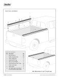
HIS 305 Long Bed User’s Manual
Introduction
Thank you for purchasing your HighCountry spray system. We have designed your system to be trouble
free and low maintenance for many years to come. It is our intention that you now have one of the
most productive tools in your equipment arsenal. Please take a short time to familiarize yourself with
this manual and observe the cautions included to assure safe and productive operation.
Thank you for joining our family of HIS system users.
Table of Contents
1- Installation and Setup…………………………... 2
2- Use and Care ………………………………………….6
a. How to fill from a storage tank…..6
b. How to use the boom ………………..7
c. Speed and coverage chart …………8
d. Use of hose ………………………………..9
e. Cautions and reminders ……….…..9
1
Section 1 -Installation & Setup
If your system came on a pallet, remove the sides of the pallet, cut the black hold down bands on the
spray system skid, and remove the box of accessories. Unpack the box. Put the boom off to the side
where it won’t fall or get damaged. Using a forklift, small crane, or 4 strong men pick up the system to
allow the front legs to unfold from their position tucked up under the frame. Put clip pins in to keep
front legs from folding back up. Then install the back legs using the hitch pins provided.(pic 2) Set the
system down on the 4 legs. (pic 1) Recycle the pallet if possible.
All long bed pickup trucks:
Your system is ready to slide into the truck. Remove the tailgate and put in a safe place. Back the truck
up to the system so the bumper touches the front legs gently. The front edge of the steel frame should
overhang into the bed. If you have a new truck or a bed liner, spray common silicone spray on the bed
surface in front of the system frame. This will allow the system frame to slide with minimal scraping of
the bed paint or bedliner. Remove the clip pins from the front legs. Pick up the front end of the system
by manually lifting and kicking the front legs toward the rear (into fold-up position). With the front of
the system resting on the bed of the truck (NOT the bumper) back the truck up slowly with one person
at the rear of the system pushing and wiggling until the system is fully in the bed. Check to assure that
the system if firmly up against the bulkhead of the bed. (pic 3) Using a tape measurer center the system
in the bed side to side. Remove the rear legs and set aside with the clip pins.
When you are confident the system is firmly against the bulkhead of the bed and well centered, attach
the ratchet strap to the cargo hold-down hooks or loops in the back corners of the bed. (If your bed
does not have hooks, please call our office for special instructions) Run the strap across the back of the
system frame creating forward push into the bed. Ratchet the strap so that there is noticeable tension
on the strap but not a super-tight feel.
For flat bed trucks-If your flat bed is 8 ft long, proceed as above, except you will need to anchor the skid
frame to the bed of the truck with an additional set of bolts (not provided) If your bed is longer than 8 ft
we suggest using a combination of 2x4 and 4x4 boards to space it back enough for the boom to clear.
Attempt to install the boom from the bottom up into operational position.(pic 4) If it fits easily, use the
clip pin to set for 22-25 inches off the pavement. If the bumper protrudes so as to block installation of
the boom you should loosen the ratchet strap and cut a piece of 2x4 to put on the front edge of the
system frame between the frame and the bed bulkhead. This spacer should move the system rearward
enough to clear the bumper. Retighten the ratchet strap. Confirm system is centered in the truck bed
with a tape measurer.
Using a 3/8” drill bit, drill a hole through each of the mounting tabs on the side edge of the frame
toward the rear. These will be the only holes in the bed (for pickup)and are for positioning only. Put the
3/8” x 2” long hitch pins through the holes. Add a flat washer to the bottom and clip from below in
tightest possible hole.
2
For flat bed- Drill two holes thru the frame channel approx. 18 inches from the front of the frame and
thru the deck of the flatbed. Bolt down firmly. Replace the rear locator pins mentioned above with
bolts.
Take the wiring harness and put into the cab. Stretch power adapter (cigarette lighter plug) to a known
working power plug and insert. Notice the LED light on the adapter. Position the switch box on the
seat. The switch can be attached to a proper place on a cloth seat with velcro for convenient use if
desired. Snake the flat cable under the seat and out the passenger door. Assure the flat cable passes
thru the door as flat as possible to reduce chance of damage. Route as necessary thru the bed to
protect. Connect the 3 wire connector to the matching connector on electric valve. The electric valve
has an off/on mark on it. With the ignition on, confirm that the LED light on the adapter is on. Flip the
cab control switch to the “on” position. The electric switch in the back should move and the arrow point
to the on position. Turn the cab control switch to off and confirm the valve moved back to the off
position. System is now ready to be filled and used.
If desired, a piece of clear bra material can be purchased from an automotive detail shop to protect the
truck’s paint where the power cable goes thru the door and into the bed.
Pic 1- System ready to load into truck.
3
Pic 2- Back leg detail with hitch pin in place.
Pic 3- push unit in so frame contacts the bed bulkhead firmly.
4
If you have to drive long distances with the tank unloaded put a small ratchet strap (blue in the pic)
across the front of the frame to keep it from bouncing or shifting.
Pic 4- Boom in “use” position. Boom’s vertical brace should clear the bumper by at least 3/4”
5
Section 2- Use and Care
Part 1- to fill the system from a storage tank
If your spray system is new or if you drained the pump since last use it is usually helpful to manually
prime the pump. Remove the 4 sided plug from the top of the priming port shown here.
Pour 1-2 qts of warm water or the solution you will be spraying into the port. Replace the plug snugly.
Hook a non-collapsing hose to the storage tank and to the input port on the system. (2” cam-lock
fittings) Put the “source” valve in fill position. Put the fill valve into “fill” position.
Source valve in fill position.
Fill valve in fill position
When hose is connected and valves are set, open the valve on the storage tank and start the motor.
System tank will fill at a rate of about 40 gallons per minute. When full, shut the motor off, then close
the storage tank valve. Then turn the “source” valve to vertical or off position. Remove the hose, and
cap off the input port. Return the fill valve to the “off or “use” position.
6
Part 2- How to use the boom for normal spraying
When on site for a spray job, turn the source valve toward the system tank.
Then turn the output valve to the left position for boom. (Right is for the hose)
Output valve:
Make sure wiring harness is plugged in securely to the 3 wire connector near the pump, and into the
cigarette lighter/power port in the truck. Check the LED on the power port plug which should be on to
be ready to use. Change the cab control switch to on, and visually verify the valve changed. Turn off.
The boom must be in the “use” position and the hose connected like this:
7
Then start the motor. Run the engine speed up to a high idle. Open the “fill valve” momentarily (5
seconds)and re-close to prime the pump. Hold the button on the flow meter to reset the gallons used.
Turn on the cab switch. Observe the pressure gauge. Increase engine speed until gauge reads 35-40 psi.
Turn off and position truck for first pass. Note- Valve takes about 1.5-2 seconds to engage or disengage
after switch is changed. Adjust driving accordingly.
Spray coverage chart
Low flow spray heads, 6 heads at 1.5 gal per minute(40 psi) is 9 gal/min in a path 8 ft wide
Speed
12 mph
10 mph
7 mph
coverage
938 sq ft/gal
782 sq ft/gal
547 sq ft / gal
You can change your coverage by changing the vehicle speed, or by changing the output pressure
through changing the engine speed. If you do not have recommendations from your liquid provider,
always start around 1 gal per 900-1000 sq ft. (ie set the throttle on the motor so you have 35 psi and
drive as close to 12 mph as possible) Use your measurements of the lot and your flow meter reading to
determine sq ft per gallon actually applied.
8
Section 2- Use of hose
To use the hose, either reel equipped version or 25 ft coil, simply turn the output valve to the right, and
turn the cab control switch to the “on” position. Then start the motor and use the spray gun like any
other spray. Remember to turn the cab control switch off and return the output valve to the “boom”
position. (left)
Cautions and reminders*** Important ! Do not overload your truck. (exceed the manufacturers gross
vehicle weight rating GVWR) Many deicing/dust control liquids weigh almost 11 lbs per gallon. Your
spray system weighs around 650 lbs. Do the math for the product you use and the truck you have.
*Check the tension on your ratchet strap often for the first month as the straps do stretch a little. Do
not overtighten as damage to the truck bed tie-down points will occur.
*check engine oil frequently during the season. Change oil yearly. Honda motors live long with clean oil.
* Do not run the pump for more than 5 minutes without spraying. Pump overheating and damage could
occur. Shut the motor off if there is any possibility of being longer than 5 minutes.
*If transporting for longer distances on roads with any liquid on them, cover the motor and the pump
with a tarp. The mist/dust kicked up at highway speeds or on a treated road is hard on the motor.
*** Important ! do not attempt to unload spray system from truck with liquid still in system tank.
Empty tank, and then remove from truck. Damage to system legs or injury to operators can occur if not
empty.
* For safest operation and least risk for boom damage, return boom to the travel position when spraying
is done or traveling between jobs involves and significant distance. Assure that clip pin is fully clipped.
Travel position
*At the end of the season empty the system tank, and add 20-30 gallons of water. Flush the system by
running the pump with the fill valve in fill position (priming the pump). Then change the valve to use
9
and discharge out both the boom and the hose/ spray gun. Run the pump until no more pressurized
water comes out. Shut motor off. Then open the drain cock on the bottom of the pump. This drains the
pump chamber itself and most of the system.
*Do not attempt to use this system with powder based chemicals. The recirculation system is not
designed to keep powder in suspension. Use liquid based chemicals only. Liquid concentrates are OK.
Please feel free to email or call with any questions. We cannot provide guidance on mix proportions for
chemicals or application rates other than ice/dust control. All other questions are welcome.
Email [email protected]
Phone 303-838-4233
See our blog at http://highcountryis.com/blog/ for general info on anti-icing and dust control spraying.
10