1
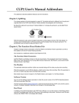
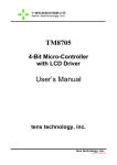
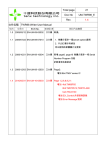
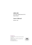
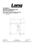
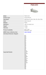
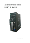
Hardware User’s Manual
Table of Contents
1. Hardware Accessories
2. MCU models that it can support
3. Installation
4. Manual for Panel Use
1
Rev:1.1
1. Hardware Accessories
1.1
1.2
1.3
1.4
1.5
1.6
1.7
1.8
ICE 1 set
TM8795 Writer Board 1 set
DC Adapter 1 pcs
Printer port cable 1 pcs
Bus line(16pin) 1 pcs
Bus lines (40pin) 2 pcs
Installation CD 1 pcs
One copy of hardware installation
2. MCU Models that it can support
This development can support the following 4-bit MCU products:
TM8704,TM8705,TM8706,TM8712,TM8713,
TM8740 (note 1),TM6811,TM6814,TM6820,TM6840,TM6841,
TM8795 (note 2).
Note 1: If clients need to develop TM8740 products, the products have to
be used together with TX9010 EV Board. For details, please
contact our sales department.
Note 2: TM8795 is a OPT product, the products have to be used together
with TM8795 Writer Board.
2
Rev:1.1
3.Installation
3.1 Step1:Please make sure the printer port on the computer is set to
be EPP Mode.
3.2 Step2:Connect printer port cable to the computer and the printer
port on ICE, as shown in Figure 1.
Figure 1
3.3 Step3:Insert the DC Adapter to ICE, as shown in Figure 2.
Figure 2
3.4 Step4:Turn Power switch to ON position.
3.5
Hardware is installed on your computer successfully.
3.5 Now, you can start to install software. First, put the CD disk into
the computer. Then, follow the instructions to install software
Application. After the completion, the operation may begin.
3
Rev:1.1
4. Manual for Panel Use
Figure 3
Figure 4
4
Rev:1.1
1. SW1,SW2,SW3
u SW1: setting the work voltage of chip and please refer the details
to Table 1.
u SW2: setting LCD BIAS; please refer the details to Table 2.
u SW3: setting LCD Pump voltage; please refer the details to
Table3.
u Example: If the setting of the *.opt file from the clients is
operating voltage of 3v and 1/4BIAS, the setting of SW1, SW2
and SW3 should be like Figure 5.
Figure 5
2. JP8, JP9: connecting to external testing boards or LCD panel signal.
Please refer to Figure 6.
Figure 6
5
Rev:1.1
3.External pins for External clock: Fast-R and Slow-R&C.(Note: 1)
3.1 Example: Refer to Figure 7 for the way of connecting Fast-R pin.
Figure 7
3.2 Example: Refer to Figure 8 for the way of connecting Slow-R&C
pin.
Figure 8
4.RFC external pins: RR, RT, RH and CX.
4.1 Example: Refer to Figure 9 for the way of connecting RR, RT,
RH and CX pin.
Figure 9
6
Rev:1.1
5. Reset, INT buttons:
5.1 Reset:chip reset request signal.
5.2 INT:External interrupt request signal.
5.3 For details, please refer to each Chip user’s manual.
6. LED Status Display:( Hi => ON ; Lo => OFF )
u VDDC :ICE POWER. (ON:Hi ; OFF:Lo)
u ECSF : Fast / Slow clock status.(Fast:Hi ; Slow:Lo)
u OU :STACK Over/Underflow status.(STACK Over/Underflow:Hi ;
normal:Lo)
u
u
u
u
HALT : HALT status.( HALT mode:Hi ; HALT release:Lo)
STOP : STOP status.( STOP mode:Hi ; HALT release:Lo)
STEP : Free run /Single step status.(Free run:Lo ; Single step:Hi)
MATCH : Compare H/W(sw1,sw2,sw3) setup with S/W(.opt file)
setup. (the same:Hi)
u TCK2, ICE, CONF : These three LED statuses are for
engineering certification. Therefore, clients do not need to pay
attention to them
7. EXT-V,VDDC,GND :
7.1 EXT-V:External VDDO pin.(Note:2)
7.2 VDDC:5 voltage.
7.3 GND: ground .
8. DC-IN : 9V DC input.
9. Printer port : connect PC.
10. Power switch.
7
Rev:1.1
11. JP7:TM8740 Bus line for externally connected boards. Please refer to
Figure 9.
Figure 9
12. JP10: TM8740 Bus line for externally connected boards. Please refer
to Figure10.(Note :3)
Figure 10
8
Rev:1.1
Table1. POWER SETTING
SW1 of VDDO settint
Function
5v
Bit1
1
Bit2
0
Bit3
0
Bit4
0
Bit5
0
3v
0
1
0
1
0
1.5v
EXT-V
0
0
0
0
1
0
1
0
0
1
Table2. CUP0~CUP2 CAP SETTING
Function
SW2 CAP of CUP0~CUP2 setting
Bit1
Bit2
Bit3
Bit4
DC
0
0
0
0
1/2 BIAS
1/3 BIAS
0
0
0
0
1
1
1
1
1/4 BIAS
1
1
1
1
Table3. VDD1~VDD4 CAP SETTING
SW3 CAP of VDD1~VDD4 setting
Function
Bit1
Bit2
Bit3
Bit4
Bit5
Bit6
Bit7
Bit8
DC
1.5V Ag 1/2
1
1
0
0
1
0
0
1
1
1
0
0
1
1
0
0
1.5V Ag 1/3
1
0
0
1
0
1
1
0
1.5V Ag 1/4
3V Li 1/2
1
0
0
1
0
1
1
0
0
1
1
0
0
1
1
0
3V Li 1/3
0
1
1
0
0
1
1
0
3V Li 1/4
0
1
1
0
0
1
0
1
note:1 ON.
0 OFF.
9
Rev:1.1
Note 1: Under Debug mode (step, go), all clocks are provided from ICE
internal. Therefore, the external clock will only work during the
execution of Free run mode.
Note 2: It has to match SW1 and be adjusted to EXT-V for the program
to work.
Note 3: TM8795 Writer Board Use.
a. The bus line(16pin) connect JP10(TICE87NB) to
JP1(TM8795 Writer Board).
b. The JP2 signal connect to TM8795(OTP).
c. Hardware finish.
10
Rev:1.1