1
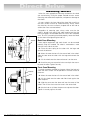
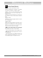
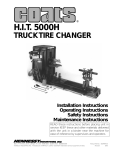
950/1025/1050/1055
Solid State
WHEEL BALANCER
Installation
Operating
Safety
Maintenance
Instructions
Instructions
Instructions
Instructions
READ these instructions before placing unit in
service KEEP these and other materials delivered
with the unit in a binder near the machine for
ease of reference by supervisors and operators.
1601 J. P. Hennessy Drive, LaVergne, TN USA 37086-3565 615/641-7533 800/688-6359
HENNESSY INDUSTRIES INC. Manufacturer of AMMCO®, COATS® and BADA® Automotive Service Equipment and Tools.
Manual Part No.: 8111868 09
Revision:
03/08
Direct Drive
ii • COATS 950/1025/1050/1055SS Wheel Balancer
Contents
Table of Contents
Operator Protective Equipment . . . . . . . . .iv
Owner’s Responsibility . . . . . . . . . . . . . . . . .v
Definitions of Hazard Levels . . . . . . . . . . . . .v
Important Safety Instructions . . . . . . . . . . .vi
Before You Begin
Receiving . . . . . . . . . . . . . . . . . . . . . . . . . . . . . . . .1
Electrical Requirements . . . . . . . . . . . . . . . . . . . . .1
Specifications . . . . . . . . . . . . . . . . . . . . . . . . . . . .1
Standard Accessories . . . . . . . . . . . . . . . . . . . . . .1
Optional Accessories . . . . . . . . . . . . . . . . . . . . . . .1
Features . . . . . . . . . . . . . . . . . . . . . . . . . . . . . . . . .2
Selecting Balancing Options
Hood Start . . . . . . . . . . . . . . . . . . . . . . . . . . . . . .12
Round Off . . . . . . . . . . . . . . . . . . . . . . . . . . . . . .12
Ounce/Gram . . . . . . . . . . . . . . . . . . . . . . . . . . . .12
Operator A/B . . . . . . . . . . . . . . . . . . . . . . . . . . . .12
Clear . . . . . . . . . . . . . . . . . . . . . . . . . . . . . . . . . . .12
Blank Rim . . . . . . . . . . . . . . . . . . . . . . . . . . . . . .12
Reading the Displays
Weight Displays . . . . . . . . . . . . . . . . . . . . . . . . . .12
Weight Position LEDs . . . . . . . . . . . . . . . . . . . . .12
Display Messages . . . . . . . . . . . . . . . . . . . . . . . .12
Balancing a Wheel
Installation and Setup
Floor and Space Requirements . . . . . . . . . . . . . . .2
Unpack and Setup the Unit . . . . . . . . . . . . . . . . .2
Connecting Power . . . . . . . . . . . . . . . . . . . . . . . . .5
Initial Testing . . . . . . . . . . . . . . . . . . . . . . . . . . . . .5
Balancer Operation Overview
Determining the Planes . . . . . . . . . . . . . . . . . . . . .6
Balancing a Wheel . . . . . . . . . . . . . . . . . . . . . . . . .6
Control Panel . . . . . . . . . . . . . . . . . . . . . . . . . . . . .7
Procedure . . . . . . . . . . . . . . . . . . . . . . . . . . . . . .13
Changing Wheel Information During Balancing . .13
Changing Balancing Modes During Balancing . . .13
Checking the Balance . . . . . . . . . . . . . . . . . . . . .13
After Balancing Vibration Checklist . . . . . . . . . . .13
Match Mount
Description . . . . . . . . . . . . . . . . . . . . . . . . . . . . . .14
Instructions . . . . . . . . . . . . . . . . . . . . . . . . . . . . .14
Maintenance and Calibration
Mounting Wheels
Back Cone Mounting . . . . . . . . . . . . . . . . . . . . . . .8
Front Cone Mounting . . . . . . . . . . . . . . . . . . . . . .8
Alternate Mounting . . . . . . . . . . . . . . . . . . . . . . . .9
Optional Combi-Adapter Mounting . . . . . . . . . . . .9
Preventative Maintenance . . . . . . . . . . . . . . . . . .16
Calibration . . . . . . . . . . . . . . . . . . . . . . . . . . . . . .16
Distance Gauge Calibration . . . . . . . . . . . . . . . . .17
Wheel Data Entry
Wheel Offset - A . . . . . . . . . . . . . . . . . . . . . . . . .10
Wheel Width - W . . . . . . . . . . . . . . . . . . . . . . . . .10
Wheel Diameter - D . . . . . . . . . . . . . . . . . . . . . . .10
1025 Watch for this symbol. It indicates that the
1050 instruction or option described is for
1055 Models 1025, 1050, and 1055 only.
Selecting Balancing Mode
Dynamic Balancing . . . . . . . . . . . . . . . . . . . . . . . .11
RV Balancing . . . . . . . . . . . . . . . . . . . . . . . . . . . .11
Alloy 1 . . . . . . . . . . . . . . . . . . . . . . . . . . . . . . . . .11
Alloy 2 . . . . . . . . . . . . . . . . . . . . . . . . . . . . . . . . .11
Alloy 3 . . . . . . . . . . . . . . . . . . . . . . . . . . . . . . . . .11
Alloy 4 . . . . . . . . . . . . . . . . . . . . . . . . . . . . . . . . .11
Static . . . . . . . . . . . . . . . . . . . . . . . . . . . . . . . . . .11
Match Mount . . . . . . . . . . . . . . . . . . . . . . . . . . . .11
COATS 950/1025/1050/1055SS Wheel Balancer • iii
Safety
✓
Operator Protective
Equipment
Personal protective equipment helps make tire servicing safer. However, equipment does not take the
place of safe operating practices. Always wear durable
work clothing during tire service activity. Loose fitting
clothing should be avoided. Tight fitting leather gloves
are recommended to protect operator’s hands when
handling worn tires and wheels. Sturdy leather work
shoes with steel toes and oil resistant soles should be
used by tire service personnel to help prevent injury in
typical shop activities. Eye protection is essential during tire service activity. Safety glasses with side
shields, goggles, or face shields are acceptable. Back
belts provide support during lifting activities and are
also helpful in providing operator protection.
Consideration should also be given to the use of hearing protection if tire service activity is performed in an
enclosed area, or if noise levels are high.
Do it Now
Make sure the instruction and warning decal is clean and clearly visible
to operator.
WARNING
Failure to follow danger, warning, and caution instructions may lead to serious personal injury or death to operator or
bystander or damage to property. Do not
operate this machine until you read and
understand all the dangers, warnings and
cautions in this manual. For additional
copies of either, or further information,
contact:
Hennessy Industries, Inc.
1601 J.P. Hennessy Drive
LaVergne, TN 37086-3565
(615) 641-7533 or (800) 688-6359
NOTICE
Read entire manual before assembling,
installing, operating, or servicing this
equipment.
iv • COATS 950/1025/1050/1055 Wheel Balancer
Safety
Owner’s Responsibility
Definitions of Hazard
Levels
To maintain machine and user safety, the responsibility of the owner is to read and follow these instructions:
Identify the hazard levels used in this manual with
the following definitions and signal words:
•
Follow all installation instructions.
DANGER
•
Make sure installation conforms to all applicable
Local, State, and Federal Codes, Rules, and
Regulations; such as State and Federal OSHA
Regulations and Electrical Codes.
Watch for this symbol:
DANGER
•
Carefully check the unit for correct initial function.
It Means: Immediate hazards, which will result in
severe personal injury or death.
•
Read and follow the safety instructions. Keep
them readily available for machine operators.
WARNING
•
Make certain all operators are properly trained,
know how to safely and correctly operate the unit,
and are properly supervised.
•
Allow unit operation only with all parts in place
and operating safely.
It Means: Hazards or unsafe practices, which could
result in severe personal injury or death.
•
Carefully inspect the unit on a regular basis and
perform all maintenance as required.
CAUTION
•
Service and maintain the unit only with authorized
or approved replacement parts.
•
Keep all instructions permanently with the unit
and all decals/labels/notices on the unit clean and
visible.
•
Do not override safety features.
Watch for this symbol:
WARNING
Watch for this symbol:
CAUTION
It Means: Hazards or unsafe practices, which may
result in minor personal injury or product or property
damage.
Watch for this symbol! It means BE ALERT! Your
safety, or the safety of others, is involved!
COATS 950/1025/1050/1055 Wheel Balancer • v
Safety
IMPORTANT SAFETY INSTRUCTIONS
READ ALL INSTRUCTIONS
1.
Eye and face protection recommendations:
“Protective eye and face equipment is required to
be used where there is a reasonable probability of
injury that can be prevented by the use of such
equipment.” O.S.H.A. 1910.133(a) Protective goggles, safety glasses, or a face shield must be provided by the owner and worn by the operator of
the equipment. Care should be taken to see that
all eye and face safety precautions are followed by
the operator. ALWAYS WEAR SAFETY GLASSES.
Everyday glasses only have impact resistant
lenses, they are not safety glasses.
2. Do not disable hood safety interlock system, or in
any way shortcut safety controls and operations.
3. Be sure that wheels are mounted properly, the
hub nut engages the arbor for not less than four
(4) turns, and the hub nut is firmly tightened
before spinning the wheel.
4. Read and understand this manual before operating. Abuse and misuse will shorten the functional
life.
5. Be sure the balancer is properly connected to the
power supply and electrically grounded.
6. Do not operate equipment with a damaged cord
or if the equipment has been dropped or damaged
– until it has been examined by a qualified serviceman.
7.
Do not let cord hang over edge of table, bench, or
counter or come in contact with hot manifolds or
moving fan blades.
8. If an extension cord is necessary, a cord with a
current rating equal to or more than that of the
equipment should be used. Cords rated for less
current than the equipment may overheat. Care
should be taken to arrange the cord so that it will
not be tripped over or pulled.
10. Wear proper clothing. Safety toe, non-slip
footwear and protective hair covering to contain
hair is recommended. Do not wear jewelry, loose
clothing, neckties, or gloves when operating the
balancer.
11. Keep work area clean and well lighted. Cluttered
and/or dark areas invite accidents.
12. Avoid dangerous environments. Do not use power
tools or electrical equipment in damp or wet locations, or expose them to rain.
13. Avoid unintentional starting. Be sure the balancer
is turned off before servicing.
14. Disconnect the balancer before servicing.
15. Use only manufacturer’s recommended accessories. Improper accessories may result in personal injury or property damage.
16. Repair or replace any part that is damaged or worn
and that may cause unsafe balancer operation. Do
not operate damaged equipment until it has been
examined by a qualified service technician.
17. Never overload or stand on the balancer.
18. Do not allow untrained persons to operate
machinery.
19. To reduce the risk of fire, do not operate equipment in the vicinity of open containers or flammable liquids (gasoline).
20. Adequate ventilation should be provided when
working on operating internal combustion
engines.
21. Keep hair, loose clothing, fingers, and all parts of
body away from moving parts.
22. Use equipment only as described in this manual.
23. Use only manufacturer’s recommended attachments.
9. Keep guards and safety features in place and in
working order.
SAVE THESE INSTRUCTIONS
vi • COATS 950/1025/1050/1055 Wheel Balancer
Direct Drive
Before You Begin
Receiving
The shipment should be thoroughly inspected as
soon as it is received. The signed bill of lading is
acknowledgement, by the carrier, of receipt in good
condition of the shipment covered by our invoice.
If any of the goods called for on this bill of lading are
shorted or damaged, do not accept them until the carrier makes a notation of the shorted or damaged
goods on the freight bill. Do this for your own protection.
NOTIFY THE CARRIER AT ONCE if any hidden loss or
damage is discovered after receipt and request him to
make an inspection. If the carrier will not do so, prepare an affidavit to the effect that you have so notified
the carrier (on a certain date) and that he has failed to
comply with your request.
IT IS DIFFICULT TO COLLECT FOR LOSS OR DAMAGE AFTER YOU HAVE GIVEN THE CARRIER A
CLEAR RECEIPT.
File your claim with the carrier promptly. Support
your claim with copies of the bill of lading, freight bill,
invoice, and photographs, if possible.
Although Coats responsibility ceases upon delivery
of the shipment to the carrier, we will gladly assist in
tracing lost shipments. Our willingness to assist in
every possible manner does not make COATS responsible for collection of claims, or replacement of lost or
damaged materials.
Electrical Requirements
Specifications
• Cycle time . . . . . . . . . . . . . . . . . .5 seconds (avg.)
• Outside Tire Diameter . . . . . . . . . .40 inches max.
• Max Tire Weight . . . . . . . . . . .150 pounds (68 Kg)
• Wheel Diameter Range . . . . . . . .10 to 24 inches
• Wheel Width Range . . . . . . . . .2.7 to 18.6 inches
• Balancing Increments . . . . . . .0.25 or 0.01 ounce
• Resolution (Round Off Mode) . . .0.01 ounce, 1.4°
• Motor - Modified torque with 900 RPM/1.5 HP rating, forced air cooling, large housing for heat dissipation, and heavy duty insulation for high
temperature applications.
• Shipping Weight . . . . . . .550 pounds (249.79 Kg)
Standard Accessories
• Graduated Cone Assortment (hardened, 3 piece)
• Large Adapter (truck cone)
• Cone Spring
• Hub Nut
• No-Mar Ring
• Rim Width Calipers
• Wheel Weight Pliers
Optional Accessories
• Combi-Adapter for Bolt Hole Mounting
• Extra Large Truck Cone Kit
• 3, 4, and 5 Lug Universal Adapters
• Escort/Lynx Adapter
The balancer requires a 220 VAC, 60Hz, three-phase
power supply with 20 amp fuse or circuit breaker, or a
220 VAC, 60 Hz, single-phase power supply with 20
amp fuse or circuit breaker.
• Speed Lock Kit
The three-phase balancer is equipped with an
approved cord and a 4-prong grounding plug to fit a
Hubbell 2420 or Bryant 71520 grounding receptacle
(not included).
• Large Truck Cone and Cup Adapter Kit Assembly
and Setup
• Side and Rear Storage Trays
• Additional Accessory Pegs (for rear of balancer)
• Viper Wheel Kit
The single-phase balancer is equipped with an
approved cord and a 3-prong grounding plug to fit a
Hubbell 2320 or Bryant grounding receptacle (not
included).
The receptacles should be installed by a qualified
electrician in accordance with state and local codes.
COATS 950/1025/1050/1055 Wheel Balancer • 1
Direct Drive
Features
• Exclusive Direct Drive System - No Belts
or Pulleys
Installation and Setup
• Hood Safety Interlock System
A factory trained COATS® Service Technician must perform the
install, setup, and initial test procedures on your 950, 1025,
1050, or 1055 balancer. Do not attempt to install and setup the
unit yourself. Accurate and reliable operation of your unit
depends on proper installation. Please contact COATS® directly
at 1-800-688-9240 for the Certified Service Partner nearest you.
• Extended Mounting Flange for Deeper
Wheels
Floor and Space Requirements
• Single-Spin Balancing
• Vertical Wheel Mounting
• Removable Center Shaft for Closed Center
Wheels and Combi-Adapter Mounting
• Dynamic, Static, RV, Match Mount, and
four Alloy Balancing Modes
• Adjustable Control Panel
- Scratch and Solvent Resistant
- Large, Bright Digital Displays
- Easy-to-Read Position Indicators
- Large Keypad for Data Entry
- Easily Repositioned for Best Visibility
- Electronics Isolated from Motor Heat
The balancer must be located on a flat floor of solid construction, preferably concrete. The balancer must sit solidly on its 3
feet. If the balancer is not level, does not sit solidly on its 3 feet,
or is placed on an unstable floor, the balancer will not function
properly and will produce inaccurate balance readings.
The balancer is not designed to be bolted down, nor will it
function properly if left on the pallet.
Select a location for the balancer that provides a level, solid
floor, and adequate clearance around and above the balancer
(Figure 1). Make sure the location selected has enough room
above and behind the unit so the hood can be raised completely.
The location must also provide working room for mounting and
removing wheels.
- Automatic Memory and Program Check
6 Ft.
6 Ft.
• Operator A/B
• Automatic Data Entry for Offset and
Diameter
• Self-Calibrating
• Wheel Weight Bins - Standard, Custom,
and Tape-A-Weight
• Four Storage Pegs for Accessories
7 Ft.
• Convenient Cone and Hub Nut Storage in
Top Tray
• "No Bolt-Down" Installation
• Side Storage Tray for Extra Wheel Weights
(optional on 950)
• Solid State Motor Control
Figure 1 - Space Requirements
Unpack and Setup the Unit
1. Remove the carton from the pallet.
2. Remove the shipping bolts in the three support feet.
3. Cut the strap holding the hood in shipping position.
CAUTION
Do not use the control pod, control pod arm, faceplate, hood or stub shaft to lift the balancer.
CAUTION
Use help to remove the balancer from the pallet. The
unit is heavy and the weight is not evenly distributed. Dropping the unit may cause personal injury or
equipment damage.
2 • COATS 950/1025/1050/1055 Wheel Balancer
Direct Drive
4. Lift the balancer off the pallet.
5. Open the accessory box and remove the hood assembly
hardware and hood spring.
6. Install the hood stop if not already pre-assembled.
Cap Plug
Retainer Washer,
1-1/2 ID
Hood
Flanged Bracket
Bearing
Flanged
Bearing
CAUTION
Improper hood assembly installation may result in
mechanical switch damage causing the balancer not
to operate. Use help and carefully follow the hood
assembly installation instructions as described
below.
Stationary
Hood Bar
Figure 2 - Hood Assembly Installation
7. Locate the hood assembly.
8. Slide one flanged bearing onto the stationary hood bar;
flange to cam (figure 2).
9. Next, install the hood assembly to the hood bracket.
10. Slide the other flanged bearing into position followed by
the washer, retainer and cap plug (figure 2).
11. Raise the hood all the way and verify that the hood stop
bracket on the side of the hood contacts the rubber hood stop
solidly. Lower the hood and verify that the other end of the hood
stop bracket contacts the rubber hood stop solidly.
12. Raise the hood and hold it up.
CAUTION
Use help to hold the hood while attaching the hood
spring. Attaching the spring without holding the
hood in place may cause it to snap open suddenly,
resulting in personal injury.
13. Hook the other hook end of the hood spring under the
balancer.
14. Hook the other end of the spring over the pin in the rear
of the hood stop bracket. Make sure the spring fits into the
grove in the pin.
COATS 950/1025/1050/1055 Wheel Balancer • 3
Direct Drive
15. Loosen the four 5/16" nuts and raise the control pod support arm. Raise it high enough to allow room for the pod to
rotate into position and for the Match Mount instructions to
lower below the pod.
16. Lightly tighten the control pod support arm retainer nuts
on the side of the support bracket. Arm will be adjusted and
tightened later.
17. Loosen the two adjustment knobs on the back of the
control pod (Figure 6).
Adjustment Knobs
Figure 6 - Control Pod Adjustment Knobs
18. Rotate the pod into operating position, and retighten the
knobs.
19. Loosen the nuts on the support arm retainers. Raise or
lower the control pod into the desired position, and tighten the
retainer nuts securely. The bottom edge of the pod should be at
least 8 inches above the top of the balancer (Figure 7).
20. Lower the Match Mount instructions attached to the
underside of the control pod. If there is not enough room
between the pod and the balancer weight tray to fully lower the
instruction card, the pod should be raised.
8" Min.
Figure 7 - Control Pod Height
21. Position the balancer in its final operating location.
Lightly tighten the four 5/16" nuts
22. Install the wheel caliper hook on the outside of the hood
(away from the balancer). Remove the 1/4" screw (towards the
rear of the hood), position the caliper hook over the hole, and
reinstall the screw.
23. Install the side pocket (1050 standard, 950 optional) and
accessory peg brackets/covers (950 and 1050 standard).
Mounting holes are provided on the side and rear of the balancer to allow the pockets and peg brackets to be installed
according to user requirements. Mount up to three side pockets or two peg brackets on the side or the rear. Contact your
Hennessy Representative to order additional pockets or brackets.
4 • COATS 950/1025/1050/1055 Wheel Balancer
Direct Drive
Connect to Power
Three-Phase
Your factory trained COATS® Service Technician should do the
final check to verify the power installation before connecting the
balancer to a power supply. Failure due to improper power connection will void the warranty.
Connect the balancer to an appropriate electrical receptacle.
Refer to Figure 8 and 9, as well as Electrical Requirements on
page 1.
Note: If pedestrian or equipment traffic might damage the
standard power cord, power outlets must be enclosed in a raceway on the floor or in an overhead drop.
Note: Electric outlets must be solidly connected. There should
be less than 1 Ω electrical resistance between the ground pin
and earth ground. The installer or electrical inspector must verify the outlet installation before connecting the balancer. Failure
due to improper power connection will void the warranty.
Ground
Hot
Hot
195-230 V
Between
Hot Wires
Hot
Figure 8 - Three-Phase Wiring Diagram
Single-Phase
Green/
Ground
Note: The green wire in the cord is the grounding wire. Never
connect the green wire to a live terminal.
Initial Testing
This should be performed by your factory trained COATS®
Service Technician.
A – Red
1. If the circuit breaker for the balancer outlet is off, turn it on
now. Turn the balancer ON/OFF switch to ON.
B – Black
Figure 9 - Single-Phase Wiring Diagram
Remember: To maintain the proper operating temperature for
the balancer, the unit should be left on all day.
2. The displays will show zeros when the unit is first turned
on. Press any key to continue.
3. Verify that the fan is running by placing your hand between
the arbor faceplate and the motor housing. You should feel air
coming out from around the motor housing. Do not operate the
balancer if airflow is not present when the balancer is on.
4. Lower the hood and press START. The arbor faceplate
should spin in the direction indicated by the label at the outer
edge of the motor cover (clockwise when viewed straight on).
If the faceplate spins counterclockwise, turn the balancer off,
turn the circuit breaker off, and disconnect the balancer plug.
Swap two of the hot wires connected to the receptacle.
Reconnect the balancer to the receptacle, turn the circuit
breaker on, then turn the balancer on. Lower the hood and press
START and recheck the direction of the spin. The faceplate
should now be spinning in a clockwise direction.
Note: Single-phase balancers will also spin in a clockwise
direction.
Note: Disregard a short spin cycle with HUB displayed on the
control panel during this initial testing.
5. Raise the hood during a spin cycle to verify that the hood
interlock system is functioning properly.
COATS 950/1025/1050/1055 Wheel Balancer • 5
Direct Drive
Balancer Operation
Overview
This machine is a two-plane, microprocessor-based computer
balancer. Any imbalance in a wheel, either static or dynamic, is
resolved into two correction planes (usually the inner and outer
flanges of the wheel) where corrective weights can be applied.
Pressing MODE and selecting the DYNAMIC, ALLOY, STATIC,
or RV mode can change the location of these planes.
Determining the Planes
1025 When the distance gauge is pulled out and held
1050 against the wheel flange, the computer automatically
1055 registers the distance (referred to in these instructions
as the A Offset measurement). The computer will "beep" to indicate it has stored the measured distance. This distance measurement (the Offset) tells the computer the location of the inner
plane of the wheel for Dynamic balancing.
1025 While the distance gauge is held in contact with the
1050 wheel flange, the computer also calculates the wheel
1055 diameter (D measurement). The diameter measurement is automatically entered (along with the offset measurement) when the computer BEEPS. The diameter measurement
tells the computer how far from the center of the hub the
weights will be applied.
The offset and diameter measurement principles are the same
for the 950, however the operator must enter the measurements, instructions on page 8.
When the wheel width is entered into the computer, it is automatically added to the offset measurement to determine the
outer plane of the wheel. The wheel width is entered manually
by the operator as the W measurement.
Balancing a Wheel
When a wheel is spun, the balancer detects any imbalance
present. The computer calculates the weight needed to correct
the imbalance and the location for weight application. The
weight required to correct the imbalance is displayed on the
control panel, and the weight positioning lights assist the operator in positioning the weight application location at top-deadcenter. Weight displays and positioning lights are provided for
both inner and outer planes of the wheel.
The stop-on-top feature of the 1050 is designed to stop the
spinning wheel with the outer weight application location near
top-dead-center, if no imbalance is detected.
6 • COATS 950/1025/1050/1055 Wheel Balancer
Direct Drive
2
19
18
1
3
4
5
6
7
8
9
10
11
12
19
20
18
20
16
15
14
17
13
Control Panel
1 Keypad - User enters information and selects
function using these keys.
Wheel Measurement Display - Displays A, W,
and D values.
2
3 Wheel Offset (A) - The distance between the
inner rim flange and the edge of the balancer. Refer to
Data Entry beginning on page 9 for detailed instructions.
Wheel Width (W) - The width of the rim between
the inner and outer rim flanges. Refer to Data Entry
beginning on page 9 for detailed instructions.
4
Wheel Diameter (D) - The diameter of the wheel
at the weight location. Refer to Data Entry beginning
on page 9 for detailed instructions.
5
6 Calibrate - Places the balancer in the Calibrate
Mode. Press and hold the SHIFT key, and press 1.
1025 7 Clear - Clears all entered measurements
1050 and user preferences for the operator memory
1055 in use (Operator A/B). The other operator
memory remains intact. Press and hold the SHIFT
key, and press 2.
8 Hood Start - Sets the balancer to automatically
start the spin cycle when the hood is lowered. Press
and hold the SHIFT key, and press 3. Repeat the key
sequence to turn the option off.
1025 9 Blank Rim - Turns the wheel diameter
1050 measurement display off (balancer continues
1055 to utilize this measurement). Press and hold
the SHIFT key, and press 4. Repeat the key sequence
to turn the display back on.
11
Operator A/B - Toggles the balancer
1050 between two operator memories. Allows the
balancer to be used by a second operator
without clearing the measurements or data stored by
the first operator. All measurements and preferences
entered into one operator memory are retained when
the other operator memory is selected. Press and
hold the SHIFT key, and press 7.
12 Ounce/Gram - Toggles the balancer between
ounces or grams. Press and hold the SHIFT key, and
press 9.
13
Mode - Selects the desired balancing mode.
14 Balancing Modes - Press the MODE key to
select from the 8 available modes. The LED above the
mode will illuminate to indicate the mode is selected.
15 Weight Unit LEDs - Indicates that weight readings are shown in ounces or grams (see 12).
1025 16 Operator LEDs - Indicates operator mem1050 ory in use (see 11).
1055
17
Start Button - Press to start a spin cycle.
18 Weight Displays - Indicate the weight amount to
be attached to the wheel.
19 Weight Position LEDs - Center LEDs flash when
correct weight position is at top-dead-center.
20 Rim/Tire Reading Indicators - When lit, the
readings in the displays represent the weight values
for the rim and tire individually. Used only with MatchMount.
10 Round Off - Toggles the balancer between the
high accuracy mode (0.01-ounce increments) and the
normal mode (0.25-ounce increments). Press and hold
the SHIFT key, and press 6.
COATS 950/1025/1050/1055 Wheel Balancer • 7
Direct Drive
Mounting Wheels
Select the most appropriate mounting method for the wheel
you are balancing. Using the proper method ensures secure
mounting and safe balancer operation, and prevents damage to
the wheel.
On most wheels, the inner side of the wheel hub usually has
the most uniform surface for wheel balancing. Always center
the wheel by the most uniformly shaped side of the hub to
achieve the most accurate balance.
Regardless of mounting type, always make sure that the
wheel is forced firmly against the arbor faceplate and that the
hub nut engages the threaded arbor for at least four complete
turns. To assist in centering the wheel properly, rotate the wheel
on the arbor while tightening the hub nut.
Rim
Hub Nut
Cone
Back Cone Mounting
Most original equipment and steel wheels can be mounted
properly using this method. The wheel is centered on a cone
from the inner side of the hub.
1. Place the cone spring on the arbor with the large end
towards the balancer.
2. Select the cone that best fits the center hole in the wheel.
Slide the cone onto the arbor with the large end towards the
spring.
Spring
Pressure Cup
3. Lift the wheel onto the arbor and center it on the cone.
Figure 10 - Back Cone Mounting
4. Attach the pressure cup to the hub nut and spin the assembly onto the arbor. Tighten securely.
Front Cone Mounting
Hub Nut
Cone
A wheel should be centered by the outer side of the hub only
when the inner surface will not provide an accurate surface to
center on.
1. Select the cone that best fits the center hole in the wheel.
2. Lift the wheel onto the arbor and slide it back against the
arbor faceplate.
3. Slide the cone onto the arbor and into the center of the
wheel. Then lift the tire to seat the cone in the center hole.
4. Spin the hub nut (without the pressure cup) onto the arbor.
Tighten it securely against the cone.
Rim
Figure 11 - Front Cone Mounting
8 • COATS 950/1025/1050/1055 Wheel Balancer
Direct Drive
Alternate Mounting
If the wheel has a protruding outer hub which will not permit
the use of the pressure cup, or the cup will not permit the hub
nut to engage at least four turns of the arbor, this alternate
method should be used.
Spring
No Mar Ring
1. Place the cone spring on the arbor with the large end
towards the balancer.
2. Select the cone that best fits the center hole in the wheel.
Slide the cone onto the arbor with the large end towards the
spring.
Cone
3. Lift the wheel onto the arbor and center it on the cone.
Hub Nut
4. Use the small nylon spacer (no-mar ring) or a centering
cone to press against the outer wheel hub.
5. Spin the hub nut (without the pressure cup) onto the arbor.
Tighten securely
Optional Combi-Adapter Mounting
Use this method for wheels without a center hole, for a center hole that is out of round, or center holes that do not fit the
mounting cones. This adapter allows the mounting of 3, 4, 5, 6,
8, or 10 lug wheels by installing 3, 4, or 5 swivel plates on the
adapter plate.
1. Assemble the adapter according to the instructions provided.
2. Attach the adapter to the wheel. The lug nuts must properly
seat in the lug holes and engage at least four full threads for a
secure mounting. Use the wrench provided with the adapter,
and never use air tools or impact wrenches.
Figure 12 - Alternate Mounting
Faceplate
Nut
Swivel Plate Bolt
Swivel Plate
Number
Gear
Center
Bushing
Alignment
Mark
Washer
(optional)
Combi Plate
Alignment
Figure 13 - Optional Combi-Adapter
3. Remove the threaded arbor (if necessary for wheels without a center hole).
4. Lift the wheel onto the balancer and align the adapter base
plate studs with the holes in the arbor faceplate. Secure the
adapter/wheel to the faceplate using the thumbnuts. To properly
center the wheel, tighten the thumbnuts in an alternating pattern while rotating the wheel.
COATS 950/1025/1050/1055 Wheel Balancer • 9
Direct Drive
Wheel Data Entry
Before a wheel can be balanced, the size of the wheel must be entered into the computer. The user enters the
data either automatically or manually.
Wheel Offset - A
This is the distance between the edge of the balancer and the inner
edge of the wheel.
1025 1. For Automatic Entry - Pull the distance gauge out from
1050 the side of the balancer. Rotate it until the handle end of the
1055 gauge contacts the inner wheel flange. Hold the gauge
Offset
Touch Second
Surface of Rim
against the wheel until the balancer BEEPS to indicate it has accepted
the measurement, which is displayed above the wheel offset key.
Note: When entering A data automatically, D (wheel diameter) is
also determined and entered.
Offset Measurement Last
Legible Number
Figure 14 - Measuring Wheel Offset with Distance
Gauge
2. For Manual Entry - Press the wheel offset key. Pull the distance
gauge out in the same manner as outlined for automatic entry. Hold
the gauge against the wheel flange and read the measurement on the
gauge. Use the keypad to enter the measurement. For example, if the
last large number (inch indicator) visible is 6, and the last small number (fraction of an inch) visible is 4, press 6 then 4 on the keypad to
enter 6.4 inches.
Wheel Width - W
This is the width of the wheel measured with the calipers at the rim
flanges.
Steel
Wheels
Alloy
Wheels
Figure 15 - Measuring Wheel Width with the
Calipers
1. Press the wheel width key. If offset and diameter are entered
automatically on the 1050, the balancer will activate the width key
after the acceptance BEEP.
2. Open the calipers wide enough to reach around the tire. Close
the calipers so both tips contact the rim flanges. Read the rim width
on the calipers.
3. Enter the measurement using the keypad. It is now shown in the
display above the wheel width key.
Wheel Diameter - D
This is the diameter of the wheel at the weight location.
1025 Automatic diameter entry reads to 3 decimal places inter1050 nally and rounds to 0.10-inch values. It is not necessary to
1055 convert metric diameter measurements to inches. For man-
Figure 16 - Wheel Diameter
ual entry, enter 15.4 for 390 metric wheels, and 15.7 for 400 wheels.
The displayed value represents the diameter for weight placement
and is not necessarily representative of the actual wheel diameter. A
14-inch wheel may display 13.6 to 14.3 depending on rim lip configuration and the offset used by the computer.
1025 1. For Automatic Entry - If the wheel offset measurement
1050 was entered automatically, the 1050 has also calculated and
1055 entered the wheel diameter and displayed it above the
wheel diameter key.
2. For Manual Entry - Press the wheel diameter key. Locate the
tire size on the tire sidewall and determine the wheel diameter. Use
the keypad to enter the measurement. It is now displayed above the
wheel diameter key. The computer calculates the actual weight placement diameter.
10 • COATS 950/1025/1050/1055 Wheel Balancer
Direct Drive
Selecting Balancing Mode
Eight separate balancing modes are available on the 1050S. Select the balancing mode based on wheel type and
customer request. Press the mode key to select the desired balance type. The LED will illuminate to indicate your
selection. In the alloy and static modes, the balancer will automatically adjust the wheel diameter to compensate
for the actual location of the weight(s).
Dynamic Balancing
Alloy 3
The most common mode used for
passenger cars and light trucks.
Selecting this mode tells the balancer
that standard clip weights will be
used on the inner and outer rim
flanges.
RV Balancing
Use this mode when clip weights cannot be used, and hidden adhesive
weights are not requested. Tells the
balancer that you are using adhesive
weights on the horizontal planes on
both the inner and outer sides of the
rim.
Alloy 4
Use this mode to balance larger
wheels that do not require balancing
at 0.5 ounce or below.
Alloy 1
Use this mode when a clip weight
cannot be used on the outer rim
flange, and hidden adhesive weights
are not requested. Attach the adhesive weight to the horizontal plane on
the outer edge of the wheel.
Static
Use this mode when clip weights on
the rim flanges is not possible, or the
customer requests hidden weights.
Tells the balancer that you are using 2
adhesive weights. Inner weight will
be placed on the horizontal plane of
the wheel at the outer edge of the
inside of the wheel. The outer weight
will be placed as far to the front as
possible on the horizontal plane.
This mode balances the wheel
assembly using only a single weight
plane. It does not compensate for
side to side vibration as a dynamic balance would. Use only one adhesive
weight located as close to center as
possible on the inside horizontal
plane. If desired a clip weight maybe
used on the inner flange if 1.5 inches
is added to "D" (wheel diameter).
Match Mount
Alloy 2
Same situation as stated in Alloy 1,
but when a clip weight can be used
on the inner rim flange. Tells the balancer that you are using clip weights
for the inner rim flange, and adhesive
weights for the outer weight. Outer
weight will be placed as far to the
front as possible on the horizontal
plane.
This balancing procedure determines
the optimum positioning of the tire on
the rim so that a minimum amount of
additional weight is required to balance the wheel. This procedure
requires repositioning of the tire on
the rim. After running the Match
Mount procedure, select the desired
balancing mode and balance the
wheel. Use Match Mount when
excessive radial runout is noticed in
the tire and wheel during balancing,
when the customer complains of ride
problems, or when the balancer calls
for weight in excess of 2 ounces on
either plane of passenger car tires in
the Dynamic mode.
COATS 950/1025/1050/1055 Wheel Balancer • 11
Direct Drive
Selecting Balancing
Options
Hood Start
The balancer can be set to automatically start the spin
cycle as soon as the hood is lowered completely and the
hood safety interlock systems are engaged. Press and
hold the SHIFT key and press 3. To return the balancer to
normal mode, repeat the key sequence.
Round Off
The default weight measurement on the balancer is 0.25
ounces. The balancer can be set to a non-Round Off mode
that displays weights in 0.01 ounce increments. Press and
hold the SHIFT key and press 6 to toggle between the
Round Off and non-Round Off modes.
Ounce/Gram
In the default mode, the balancer will operate in ounces.
The balancer can be set to operate in grams by pressing
and holding the SHIFT key and pressing 9. Toggle back to
ounces by using the same key sequence. LEDs on the
control panel indicate which weight measurement is currently selected.
Operator A/B
Two operators can utilize the balancer without
1050 clearing or changing each others data. This is
handy when one operator is running the Match
Mount procedure and the other operator needs the balancer. If operator A is at a point in the Match Mount procedure where the wheel is removed from the balancer,
operator B can access the machine by switching to the
other operator memory. When B’s balance is complete, he
can toggle the machine back to A’s memory. All of operator A’s data is still present, and the Match Mount procedure can be continued without having to start over. Press
and hold the SHIFT key and press 7 to toggle between the
2 operator memories. LEDs on the control panel indicate
which operator memory is in use.
Clear
1025 This function clears the data in the currently
1050 selected operator memory only. The other mem1055 ory is unaffected. Press and hold the SHIFT key
Reading the Displays
Weight Displays
The two weight displays (one for the inner plane, and one
for the outer plane) are positioned with a wheel cross section diagram. After spinning the wheel, the balancer will
calculate the weight needed and display it in these displays. The display to the left of the diagram will show the
weight to be applied to the inner plane of the wheel and
the display to the right will show the weight for the outer
plane.
Error messages and system messages will also be
shown in these displays.
Weight Position LEDs
Each weight display includes weight position LEDs.
Located between the weight display and the diagram,
these LEDs indicate the proper location for weight application. After a spin, rotate the wheel until the center position indicator LEDs flash. This indicates that the position
specified by the balancer for weight application is at topdead-center.
Display Messages
Both inner and outer displays will show 0.00 when the
balancer is first turned on or after clearing the memory.
The balancer may also display the following messages:
Err - An error was detected after the start button was
pressed. The error is in one of the wheel measurements
entered into the balancer. Check your measurements and
re-enter as needed.
Err 3 - Circuit malfunction. Call the Hennessy Service
Department at (800) 688-6359.
Hood (hod) - The hood has been raised during the balancing cycle. The balancer will automatically brake to a
stop. The hood must be down with the safety interlock
engaged for the balancer to spin.
Hub - The hub nut has come loose. The balancer will
automatically brake to a stop when the wheel is 13 inches
or larger in diameter. Retighten the hub nut and respin.
and press 2 to clear.
Blank Rim
1025 This feature blanks out the wheel diameter
1050 measurement on the control panel display. The
1055 balancer continues to use the measurement
even though the display is blank. This feature is typically
utilized when the customer is within view of the balancer,
and may become concerned by the measurement shown
for the wheel diameter (typically when metric or odd size
wheel diameters are displayed). Press and hold the SHIFT
key and press 4 to blank the display. Repeat the key
sequence to reactivate the display.
12 • COATS 950/1025/1050/1055 Wheel Balancer
Direct Drive
Balancing a Wheel
Checking the Balance
Procedure
The following steps walk through the balancing procedure.
Do not proceed with these instructions until you have read
and understand the previous sections of this guide (mounting, balance modes, and reading the displays).
1. Turn the balancer on. The power switch is on the rear of
the unit, near the top and to the operator's left.
Note: When turned on, the balancer will activate the same
options that were selected when it was last turned off (hood
start, ounce/gram, etc.).
2. Mount the wheel to be balanced. Use the proper
mounting method as described on pages 6 and 7. Always
remove any weights attached to the wheel.
3. Enter the wheel measurements and select balancing
mode.
4. Set options (hood start, ounce/gram, operator A/B).
5. Lower the hood and press START. The wheel will spin
and then brake to a stop.
Note: Spin will start automatically when the hood is lowered if the hood start option is turned on.
After applying the weights indicated by the balancer, respin
the wheel. The displays should read 0.00.
If the balancer indicates an additional weight should be
applied in the same location as the first weight, the first
weight is too small. Correct the first weight and respin.
If the balancer indicates an additional weight should be
applied directly opposite the first weight, the first weight is
too big. Correct the first weight and respin.
If the balancer indicates an additional weight should be
applied at an angle to the first weight, the first weight was
not applied in the correct position. Move the first weight
towards the position indicated for the second weight or add
the second weight as indicated.
After Balance Vibration Problems
If vibration is still present after balancing the wheels and
driving the vehicle on smooth pavement remove the wheels
and recheck the balance. If a wheel is out of balance the
cause may be:
1. A weight has come off the wheel. Remove the other
weights from the wheel and rebalance.
7. Rotate the wheel until the outer position LEDs flash.
2. Tire slippage on the wheel. Remove and remount the
tire using proper tire lubricant and inflate to 40 PSI. Do not
over-inflate. Rebalance the wheel and reduce air pressure to
recommended PSI.
8. Attach the weight specified in the proper location at topdead-center. Refer to the diagrams on the control panel for
weight locations.
3. Stones or other foreign objects caught in the tire tread.
Remove the objects and repair tire as necessary. Check and
rebalance if needed.
9. Rotate the wheel until the inner position LEDs flash.
If the balancer still indicates the wheels are balanced to
within 0.05 ounces on both inner and outer displays, the
problem is not in the balance of the wheels. Check the following possible sources of vibration:
6. Raise the hood.
10. Attach the weight specified in the proper location at
top-dead-center. Refer to the diagrams on the control panel
for weight locations.
11. Lower the hood and press START to respin the wheel.
The wheel will brake to a stop. The weight displays should
now read 0.00. If not, refer to page 11, Checking the Balance
for assistance.
Remember: The more accurate you are in selecting and
positioning the weight, the more often you will balance
wheels with a single spin.
Changing Wheel Information During Balancing
The information entered into the balancer for A, W, and D
can be changed at anytime during the balancing procedure.
Follow the instructions provided earlier for entering the
measurements manually. The balancer will recalculate
weights and positions based on the new measurements.
1. Tire pressure. Bring all tires up to the recommended PSI.
2. Radial or lateral runout in the tire or wheel. Replace the
damaged part.
3. Foreign material inside the tire. Remove the tire from
the wheel, remove the material, and remount. Remove
wheel weights and rebalance the wheel.
4. Imbalanced wheel covers or trim rings. Remove the
wheel covers or trim rings and test drive. If the vibration is
gone, remove the arbor and use the optional Combi-Adapter
to mount the wheel to the balancer. Balance the wheel with
the wheel cover or trim ring attached to the wheel.
5. Incorrectly mounted wheel. Remount correctly.
Changing Balancing Modes During Balancing
6. Damaged wheel bolt holes. Replace wheel.
The balancing mode can be changed at anytime and the
balancer will recalculate weight and position based on the
new selection. Does not apply when switching to and from
Match Mount.
7. Worn universal joints. Replace as required.
8. Drive shaft imbalanced or damaged. Balance, repair, or
replace.
9. Imbalanced brake rotor(s) or drum(s).
10. Suspension out of alignment. Align the vehicle and
replace any damaged or worn parts.
COATS 950/1025/1050/1055 Wheel Balancer • 13
Direct Drive
Match Mount
Description
The Match Mount program assists the user in
determining the best possible mating of the tire
and wheel, thereby reducing the amount of additional weight required for balancing. This mating of
tire and wheel normally allows the least amount of
total runout of the assembly, resulting in better
balancing, better ride conditions, and more satisfied customers. Use Match Mount when:
• Excessive radial runout is noticed in the tire
and wheel assembly during balancing.
• The customer complains of ride problems.
• The balancer calls for weights in excess of 2ounces on either plane on passenger car tires
in the Dynamic mode.
Match Mount balancing requires loosening both
tire beads and inflation of the tire. You will need to
be trained in the operation of your Coats tire
changer and the dangers involved during bead
seating and tire inflation. Read the operators manual supplied with the tire changer and consult your
supervisor.
1025 The balancer will be idle while the tire is being rotated on
1050 the wheel. During these times, another operator without
1055 terminating the Match Mount procedure can use the balancer. The second operator selects the other operator memory, performs a balance, and then returns the balancer to the previous memory. The original operator can now continue the Match Mount procedure.
As with any balancing procedure, remove any weights attached to
the wheel and inspect the tire and wheel before beginning.
Instructions
1. Mount the wheel to the balancer.
2. Select the appropriate operator memory as required. Make a
note of the memory being used in the event the memory is changed
during the Match Mount procedure.
3. Enter the A, W, and D measurements and select the mode that
will be used for the final balancing.
4. Lower the hood and press START.
5. Wait for the wheel to brake to a stop and for the displays to
show weight readings.
Does the balancer indicate that 2-ounces or more is required on
either plane of the wheel in dynamic mode? Higher weights may be
indicated when using an alloy mode to compensate for weight location.
If so, advise supervisor or customer to continue with the Match
Mount procedure. DO NOT attach weights at this point.
If not, the Match Mount procedure is most likely not necessary, and
will not improve the balance. Continue to balance the wheel according to the mode selected.
Tire/wheel
assembly rotated
until valve stem
is at top-deadcenter.
6. If hood start option is on, turn it off now.
7. Press the MODE key until Match Mount is selected.
8. 1 will now be displayed in the outer weight display.
9. Raise the hood and rotate the wheel until the valve stem is at
top-dead-center.
10. Press (1) on the control panel. 2 is now displayed in the weight
display.
Figure 17 - Rotate the wheel
11. Remove the wheel from the balancer. Completely deflate the
tire by removing the valve core. After all the air pressure is
exhausted, follow the tire changer manufacturer's instruction for
loosening the tire beads.
1025 A second operator can use the balancer while the Match
1050 Mount operator does Steps 12, 13, and 14. Remember: All
1055 data for the Match Mount procedure will be kept in the
Tire rotated 180
degrees on the
wheel.
Match Mount operator's memory.
12. Lubricate both tire beads and wheel to aid in rotating the tire
and bead sealing and seating. Always use the tire manufacturer's
approved rubber lubricant.
13. Rotate the tire 180° on the wheel.
Figure 18 - Rotate Tire on Wheel
14 • COATS 950/1025/1050/1055 Wheel Balancer
Direct Drive
14. Replace the valve core and inflate the tire. Follow the tire
changer manufacturer's instructions for inflation.
1025 Remember: If another operator memory has been select1050 ed, reselect the memory being used for the Match Mount
1055 procedure. The balancer will return to the point in the pro-
Tire/wheel
assembly rotated
until valve stem
is at top-deadcenter
cedure where the other memory was selected.
15. Remount the wheel on the balancer.
16. Press (2) on the control panel. 3 is now displayed in the weight
display.
17. Lower the hood and press START.
18. Wait for the wheel to stop. Raise the hood and rotate the
wheel until the valve stem is at top dead center.
Figure 19 - Rotate the Wheel
19. Press 4 on the control panel.
Weights will now be displayed on the control panel. The weight in
the left display is the weight imbalance for the rim (as indicated by
the RIM light below the display). The weight in the right display is the
weight imbalance for the tire (as indicated by the TIRE light below the
display).
Use these weights to determine the suitability of the rim or tire.
High imbalance may indicate a rim that is out-of-round or misformed,
or a tire with a bubble or other problem. If the imbalance is excessive, it may be prudent to replace the rim, the tire, or both. If either
is replaced do not continue this procedure. Balance the new tire and
rim and evaluate the readings for Match Mount suitability.
Tire/wheel
assembly rotated
until weight position lights
flashed. Tire
marked at topdead-center.
Figure 20 - Rotate the wheel
20. Rotate the wheel until the weight position LEDs flash. Mark
the tire at top-dead-center.
21. Remove the wheel from the balancer. Completely deflate the
tire by removing the valve core. After all the air pressure is
exhausted, follow the tire changer manufacturer's instruction for
loosening the tire beads.
1025 A second operator can use the balancer while the Match
1050 Mount operator continues with Steps 22, 23, and 24.
1055 Remember: All data for the Match Mount procedure will
be kept in the Match Mount operator's memory.
22. Lubricate both tire beads and wheel to aid in rotating the tire
and bead sealing and seating. Always use the tire manufacturer's
approved rubber lubricant.
Tire rotated so
mark is aligned
with valve stem.
Figure 21 - Rotate Tire on Wheel
23. Rotate the tire until the mark is aligned with the valve stem.
24. Replace the valve core and inflate the tire. Follow the tire
changer manufacturer's instructions for inflation.
1025 Remember: If another operator memory has been select1050 ed, return the balancer to the memory being used for this
1055 Match Mount procedure. The balancer will return to the
exact point in the procedure where the other memory was selected.
Wheel ready for
balancing
25. Remount the wheel on the balancer.
26. Use the MODE key to select the desired balance mode and
balance the wheel.
Figure 22 - Match Mount Completed
COATS 950/1025/1050/1055 Wheel Balancer • 15
Direct Drive
Maintenance and
Calibration
Preventative Maintenance
The balancer requires only minor maintenance to
keep the unit operating properly.
1. Keep the display clean and clear. Use a vaporizing
cleaner only. Do not use cleaners or solvents, which
leave oily or filmy residues behind.
2. Keep the adapters, cones, faceplate, threaded
arbor, pressure cup, and hub nut clean. Grease and
dirt buildup will cause premature wear and inaccurate
balancing. Clean at least once a day with a vaporizing
solvent.
3. Clean the weight tray, accessory post, and pegs.
Weights stored in a dirty tray will pick up grease and
dirt which may alter their weight or keep them from
securely attaching to the wheel. Use a vaporizing solvent to clean the tray, pegs, and post.
4. Keep the area around the balancer clear. Remove
any tools or other items that are leaning against the
balancer. Keep the area under the balancer clear as
well. Remove any items that may cause the balancer
to not sit level.
5. Use only COATS accessories. Accessories from
other manufactures may not fit or function properly,
and may damage the balancer.
Calibration
The balancer utilizes a "self calibration" scheme. To
keep your balancer in proper calibration, this calibration procedure should be performed once a month, or
whenever the accuracy of the balancer is questioned.
1. Mount a 14, 15, or 16-inch diameter x 6 - 6 1/2inch wide steel wheel assembly on the balancer. It
should be suitable for mounting using the back cone
method and have a properly inflated tire.
2. Enter A, W, and D wheel measurements.
Note: The A entry must be between 5.0 and 8.0, and
W entry must be between 5.5 and 7.0. If the wheel
you have mounted does not meet these requirements, select a different wheel and try again.
3. Remove any weights attached to the wheel.
4. Press and hold SHIFT and press 1.
5. Lower the hood and press START.
6. Raise the hood, rotate the wheel until the outer
weight positioning LED flashes, and attach a 4-ounce
calibration weight if in ounce mode or a 100-gram calibration weight if in gram mode at top-dead-center.
Note: It is critical that this weight be placed accurately to achieve proper calibration.
7. Lower the hood and press START.
8. Raise the hood and remove the weight.
The balancer is now calibrated. If a mistake is made
during this procedure, turn the balancer off, then back
on, and start the procedure over again.
16 • COATS 950/1025/1050/1055 Wheel Balancer
Direct Drive
1025
1050 Distance Gauge Calibration
1055
1. Securely mount your calibration wheel.
2. Press and hold SHIFT and press 0. The display
will read CDE to indicate it is ready for a code.
3. Press 1 then 0. The inner weight display will now
read 0.08 to 0.22 and the outer weight display will
read 0.55 to 0.70.
4. Rotate the distance gauge to its maximum rotation (towards the front of the balancer) and hold it
there.
5. Press MODE.
6. Release the distance gauge and allow it to return
to its stored position.
7. Press MODE.
8. Pull the distance gauge out and rotate it until it
touches the inner edge of the rim flange. Hold it there.
9. Press the wheel offset key (A) and enter the distance measurement shown on the gauge.
10. Press the wheel diameter key (D) and enter the
diameter of the wheel as shown on the tire sidewall
(for example, enter 140 for a 14-inch wheel).
The inner and outer display will now change to zeros.
11. Release the distance gauge and let it return to
its stored position.
The distance gauge is now calibrated. However, the
wheel measurements displayed may vary by ±0.3
inches depending upon the condition of the rim.
COATS 950/1025/1050/1055 Wheel Balancer • 17
8111868 09 3/08
© Copyright 1997, 1999, 2000 Hennessy Industries and COATS
All Rights Reserved
Printed in USA