1
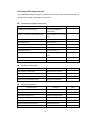
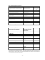
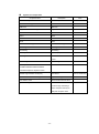
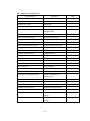
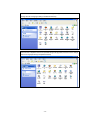
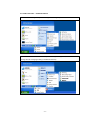
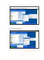
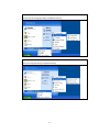
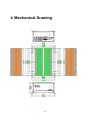
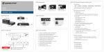
VISION BOX VB-115/VB-216 Series User’s Manual Manual Version: 2.3 Revision Date: July 13, 2010 ICP DAS CO., LTD. www.icpdas.com Table of Contents 1 Introduction ........................................................................................................... 3 1.1 Specification................................................................................................. 4 1.2 Accessories ................................................................................................. 5 1.2.1 VISION BOX Accessories ................................................................. 5 2 Hardware............................................................................................................... 6 2.1 Interface and Connection ............................................................................. 6 2.2 Hardware Installation ...................................................................................... 7 2.2.1 PCI Card Installation ......................................................................... 7 2.2.2 HDD Installation ................................................................................ 9 2.2.3 CF Card Installation......................................................................... 10 2.2.4 CF Card and HDD Master/Slave Setting .......................................... 11 2.2.5 VISION BOX COM Ports ................................................................ 12 2.2.6 ATX power remote on/off switch ...................................................... 17 3 Software .............................................................................................................. 18 3.1 Standard Operation System ....................................................................... 18 3.1.1 VB-115H/VB-216H .......................................................................... 18 3.2 XP Embedded Operation System .............................................................. 19 3.2.1 3.2.2 3.2.3 3.2.4 3.2.5 3.2.6 3.2.7 3.2.8 3.2.9 VB-115 Series/VB-216C .................................................................. 19 How to recovery Image OS? ........................................................... 19 Image OS Component List .............................................................. 23 Image OS Operation UI (User Interface) ......................................... 28 EWFShell Write-Protect Utility ......................................................... 36 OS UI Language Setting ................................................................. 39 Time Zone Setting ........................................................................... 42 Keyboard Input Language Setting ................................................... 43 Front Panel Power Button Setting ................................................... 44 4 Mechanical Drawing ............................................................................................ 45 Appendix A – Storage Performance .......................................................................... 46 Appendix B – Revision History ................................................................................. 47 Warranty Policy......................................................................................................... 48 ICPDAS Worldwide................................................................................................... 49 -2- 1 Introduction The VISION BOX series VB-115 and VB-216 with a fan-less platform design works with MAVIS or Sparrow IEEE 1394 industrial cameras for AOI (Automation Optical Inspection) applications.VB-115 standard platform is with Celeron M 1.5GHz CPU and 2GB DDR2 533 memory. VB-216 high end platform is with 1.66GHz high-speed mobile Core Duo CPU and 2GB DDR2 533 memory for advanced high-speed inspection applications. VISION BOX series associate with Windows XP embedded OS which is better on long term operation. Each VISION BOX has six USB 2.0 interface connectors and offers dual Gigabit Ethernet ports. VISION BOX series have two standard PCI bus for extension and is ideal for plug-in motion control cards such as: PISO-PS200, PISO-PS400, I/O and encoder cards for machine automation inspection applications. Features: Fan-less cooling design Celeron M 1.5GHz or Core Duo 1.66GHz Mobile, Low power consumption CPU 2 GB DDR2 533 memory High speed CF card for Windows XP Embedded OS operation Dual ports Gigabit Ethernet 2.5‖ SATA HDD supported Two 32-bit, 33MHz PCI Bus supported Target Applications Semiconductor Component inspection Quality control in Manufacturing Food and beverage inspection -3- 1.1 Specification Model No. VB-115C-N CPU VB-115H-N Intel Mobile Celeron M 1.5GHz Chipset Intel 910GM L2 Cache 1 MB Memory OS Storage 2 GB DDR2 533 PCI Bus Front I/O Interface 2.5‖ 160GB SATA Hard Disk 4GB 233x Compact Flash Card Two 32-bit/33MHz PCI Slot, Not support PCI long card. 2 x USB 2.0 Ports, ATX power on/off switch, Status LEDs (HDD Access, Power, LAN) PS/2 connector, VGA connector, 4 x USB 2.0 ports, 2 x GbE LAN ports, 4 x Serial Ports via one DB44 connector (3 x RS-232, 1 x RS/232/422/485) ,1 x SVGA, 1 x DVI Rear I/O Interface Interface, 1 x MIC-in, 1 x Speaker-out, 2-pin connector output for remote power on/off switch, DC-in power connector for +12V ~ +30V DC power input DC to DC power designed for on-board, supporting from 12 to 30VDC Power One External 120W AC adapter (Input: 100~240VAC, 2A, 50/60Hz; Output:19VDC) Dimensions 195 mm (W) x 268 mm (D) x 107 mm (H) Construction Fan-less design with aluminum cooling chassis Operating temperature Ambient air temperature : 0°C to 40°C VISION BOX case ( Surface Temperature of Chassis) Environment 5°C to 45°C (W/HDD) -10°C to 50°C (W/CF card only) Storage temperature: -20°C to 80°C Relative humidity: 10% to 90% (Non-condensing) Certification CE, FCC A -4- 1.2 Accessories 1.2.1 VISION BOX Accessories Description Q‘ty AC Power Adapter 120W with power cord 1 2-pin Remote power connector 1 Accessory Photo COM Port harness cable (1 DB44 connector to 4 x DB9 ports) 1 Chipset Drivers and Image OS recovery DVD 1 QuickStart 1 Hard Disk screws 4 -5- 2 Hardware 2.1 Interface and Connection VISION BOX Front View VB-115 and VB-216 are same interface design in the front and rear. VISION BOX Rear View -6- 2.2 Hardware Installation To assure system safety and reliability, please do not use CPU and memory not recommended by ICP DAS in your VISION BOX as they may cause hazards. ICP DAS assume no liability for damages to the misuse of this product and the warranty will be voided immediately. 2.2.1 PCI Card Installation Step 1: Unscrew the 6 screws on bottom cover. Step 2: Open the bottom cover with care. Step 3: Unscrew the PCI bus triangle stand. Step 4: Let the PCI bus triangle stand straight up and unscrew the bracket. Step 5: Insert your PCI card into the PCI Bus until Step 6: Make sure the PCI card install correctly it is completely plugged in. and then fasten the bracket by screw. -7- Step 7: Make sure the rear part of PCI card is Step 8: Put bottom cover back in place and completely plugged into the card holder and screw it. screw PCI bus triangle stand properly. -8- 2.2.2 HDD Installation Step 1: Unscrew the 6 screws on bottom cover. Step 2: Open the bottom cover. Step 3:Unscrew the HDD stand Step 4: Screw 2.5‖ HDD Step 5: Plug HDD cable. Step 6. HDD stand screws. Pay close attention to SATA power cable and SATA cable at the right position. Step 7: Put bottom cover back in place and screws it. -9- 2.2.3 CF Card Installation The Compact Flash Socket is located on the top side of VISION BOX system board. Please unscrew the 6 screws of the top cover to remove the lid. Please follow the procedures below to install or remove a Compact Flash memory card. To install a Compact Flash memory To card into system board, align the memory card from system board, pull notches on the card with the Compact out the memory card from the Compact Flash socket in the system board. Then Flash socket. firmly insert the card into the socket until it is completely seated. - 10 - remove the Compact Flash 2.2.4 CF Card and HDD Master/Slave Setting The VISION BOX allows using Compact Flash card and Hard Disk at the same time. You will need to go to BIOS setup to change the system boot up priority. VISION BOX Series BIOS setting Step 1: Power on the system; hold the DEL key down until the blue BIOS screen appears. Scroll down to ‗Advanced BIOS Features‘ Step 2: Select ‗Hard Disk Boot Priority‘ Step 3: Use ‗+‘ or ‗-‗key to select options. Press ‗F10‘ to save your settings. And reboot the system. If you install only either one of CF card or HDD on VISION BOX, the system BIOS will be set as ‗Ch0 Master‘ automatically for system boot up device. - 11 - 2.2.5 VISION BOX COM Ports The VISION BOX provides four COM ports for I/O data communication from COM1 to COM4. User can connect the COM port device via COM port harness cable. Each DB9 connector assign of COM port harness cable as below. DB9 COM VB-115 VB-216 Connector Port Protocol Protocol Label No. Support Support A COM1 RS-232 RS-232 RS-232 RS-232 RS-422 RS-422 RS-485 RS-485 COM Port Appearance of COM Port Harness Cable Connector B COM2 DB44 C COM3 RS-232 RS-232 D COM4 RS-232 RS-232 The VISION BOX COM ports all set on RS-232 protocol by default setting. There is only one COM port can be support RS-422 in Full Duplex Mode or RS-485 protocol in Half Duplex Mode via COM port setting (Please refer 2.2.5.1 and 2.2.5.2). There have two connection solutions recommended, while user required to use RS-485 protocol for I/O data communication. a. Added one RS-232 to RS-485 converter in between of VISION BOX and the I/O device, for example: add one ICPDAS I-7520 RS-232 to RS-485 converter. b. VISION BOX also can be connected to RS-485 I/O devices directly without converter requirement. However this is support to use in ICPDAS‘s I7000 and M7000 series I/O products only, and user must to use DCON utility and set the Delay Time (unit: ms) for difference Baud Rate communication speed as below. Baud Rate(bps) 115200 57600 38400 19200 9600 Delay Time(ms) 2 4 6 12 24 - 12 - The 44-pin D-Sub connector is used to connect 4 external serial devices. Here is the pin assignment of the serial interface. - 13 - COM2 also supports the RS-485 and RS-422. 2.2.5.1 VB-115 series COM1 (RS-232/422/485) BIOS Setting Step 1: Power on the system; hold the DEL key down until the blue BIOS screen appears. Scroll down to ‗Integrated Peripherals‘ - 14 - Step 2: Select ‗Onboard Serial Port 1 Mode‘ Step 3: Use ―‖ or ―‖ key to select options. Press ‗F10‘ to save your settings. And reboot the system. 2.2.5.2 VB-216 series COM2 (RS-232/422/485) Switch Setting - 15 - COM2 Switch location of VB-216 - 16 - 2.2.6 ATX power remote on/off switch User can wire out to other remote power switch to control VISION BOX power on or off. - 17 - 3 Software 3.1 Standard Operation System 3.1.1 VB-115H/VB-216H VB-115H/VB-216H default did not offer any licensing system OS. We recommend that users can install licensing system OS via USB DVD player into the HDD of VB-115H/VB-216H for your application requirement. User can find the chipset drivers of VISION BOX in our recovery DVD. For the PCI interface cards or driver installation, please just follow the system OS standard operation. The Image OS files in recovery DVD are authorized legally to use in VB-115C/VB-216C only. If user want to use these Image OS files in VB-115H/VB-216H, then please contact the sales of ICPDAS to order legally Windows XP Embedded License for it. Otherwise, ICPDAS won’t allow this illegally authorization, and plus user must to take all the responsibility of Microsoft software illegal authorization. - 18 - 3.2 XP Embedded Operation System 3.2.1 VB-115 Series/VB-216C VISION BOX default standard image OS supports three UI languages: English, Traditional Chinese and Simplified Chinese. The image OS built by Microsoft Windows Embedded SP2 Feature Pack 2007. VB-115 series addition offers Windows Embedded Standard 2009 image OS files. Users can find the backup image OS on the recovery DVD. Meanwhile user can change to special image OS for difference language UI requirement. Image OS Standard-XPe Language support English + Traditional Chinese (Unicode only), Version 1.0.0.19 Simplified Chinese (Unicode only) If the OS version you require is not included above, a customized one can be provided for additional charges. 3.2.2 How to recovery Image OS? Please refer the procedure description as below for recovery the Image OS file into CF card. 3.2.2.1 Please prepare following items for Image OS recovery execution One USB DVD player One system boot up CD/DVD Please copy the recovery software into USB disk VISION BOX recovery DVD 3.2.2.2 There are two options for recovery execution, and user can choose either way for recovery process. Option1 – Plug the USB DVD player into VISION BOX USB port, and then insert the system boot up CD/DVD into DVD player. After system boot up, remove the boot up CD/DVD and insert VISION BOX recovery DVD into DVD player. In the meantime, plug the USB disk into VISION BOX USB port then follow the description of 3.2.2.3 for the recovery execution! Option2 – Please copy the system boot up files into the root path of USB disk, - 19 - then copy recovery software and the Image OS file into the USB disk too. When VISION BOX system boot up, please click ‗Delete‘ key for enter the system BIOS then set the system boot up priority from USB. After that, please restart the system then system will be boot up from USB disk. Then follow the description of 3.2.2.3 for the recovery execution! 3.2.2.3 Below example is used ―Symantec Norton Ghost32 V.11‖ as a demonstration how to do recovery the Image OS file into CF card. (The VISION BOX recovery DVD didn‘t attached any recovery software, so user must to get the legally software for it. The ―Symantec Norton Ghost V.11‖ or above version are recommend). Step1 – Open ―Symantec Norton Ghost32 V.11‖ software and click ‗OK‘. Step 2 – Select ‗Local - Disk - From Image‘ from function menu. - 20 - Step 3 – Select from path of the Image OS file. Step 4 – Select the destination of HDD or CF card for recovery the Image OS file into the path. - 21 - Step 5 – Recovery the Image OS file into CF card. Ghost software is needed to set the ‗New size‘ greater or equal with ‗Old size‘ on partition C:\ (943MB, please refer the red rectangle position of the picture). Otherwise the Image OS file may fail to recovery into the destination. Step 6 – Select the destination disk then click ‗OK‘. Once the program pop up ‗Clone Completed Successfully‘ then click ‘Restart Computer‘. After restart the computer then VISION BOX will start to run the recovery Image OS for system operation! - 22 - 3.2.3 Image OS Component List The VISION BOX image OS support component list as below. If the component list that you require is not included customization is welcomed. Programming Languages Components Component Item Description Visual Basic 6.0 Runtime Library Note Microsoft Visual Basic 6.0 runtime library Visual C++ Runtime Libraries (Side X Side) Microsoft Visual C++ 6.0 runtime library Microsoft Foundation Class Library (Legacy) MFC library .NET Framework 1.1 .NET Framework 1.1 Chinese (PRC) .NET Framework 1.1 MUI .Net 1.1 Simplified Chinese Standard-XPe only Chinese (Taiwan) .NET Framework 1.1 MUI .Net 1.1 Traditional Chinese Standard-XPe only .NET Framework 2.0 .NET Framework 2.0 Msxml 3.1 Microsoft language extension 3.1 library Explorer Application Windows Explorer library Standard Template Libraries (STL) Standard Template library Installation Components Component Item Description Add Hardware Control Panel Add new hardware device Add/Remove Programs Control Panel Add or remove program Class Installer - Stream Class Installer Safely Remove Hardware Program Safety remove hardware Note Interface Components Component Item Description Communications Port Com Port USB 2.0 USB 2.0 Support USB Mass Storage Device USB Mass Storage Device Removable Storage Service Remove storage device CD-ROM Drive CD-ROM driver Keyboard & Mouse Control Panel Keyboard and mouse Smart card Subsystem IC card or Smart card - 23 - Note Networking Support Components Component Item Description Realtek RTL8168/8111 Family PCI-E GBE Gigabit Ethernet Driver NIC" Note VB-115 series only DHCP Client Service DNS Client Windows Firewall control panel t Windows Firewall Internet Connection Wizard Internet connection wizard Internet Explorer IE 7.0 explorer Map Network Drives/Network Places Wizard Network driver connection Network Setup Wizard Network setup wizard Workstation Service Create or maintain remote client server connection Security Accounts Manager Server Library Accounts manager Security Shell Extension Security shell Simple Network Management Protocol SNMP Database Components Component Item Description Microsoft SQL Express 2005 Macro Note Microsoft SQL Server 2005 Express support* Microsoft Data Access Components (MDAC) ODBC support -- ODBC Driver Jet Database DAO Support Jet Database DAO Support Jet Database Data Extensions Jet Database Data Extensions Jet Database Engine Microsoft Jet database engine Jet Database Foreign Data ODBC Extensions Jet Database Foreign Data ODBC Extensions Jet Database ODBC Support Jet Database ODBC Support Jet Database OLEDB Support Jet Database OLEDB Support Jet Database Replication Extensions Jet Database Replication Extensions Microsoft Data Access Components (MDAC) MDAC component included ADO component Visual Fox Pro ODBC Driver Stub supplies the Visual Fox Pro ODBC vfpodbc.dll driver Microsoft SQL Server 2005 Express support* - The Image OS file built-in the Marco component of SQL Express 2005 only. Microsoft SQL Server 2005 Express Edition Service Pack2 is recommended and can be download in free via Microsoft website. - 24 - Printer Support Components Component Item Printer Common #1 (Client Side Shared Description Printer Support Components) USB Printing Support USB Printing Support Local Printing Local printing support Server Printing Server printing support - 25 - Note System Tool Components Component Item Description Accessories/System Tools System Properties Administration Support Tools Administrative Tools WMI Core WMI Core Tray Icon Add/Remove Support Tray icon add/remove CDFS CDFS UDFS UDFS FAT FAT NTFS NTFS Volume Shadow Copy Service Volume shadow copy service Event Log Event log File Sharing File sharing HID Keyboard Device Keyboard properties Indexing Service Remote server file index and Note access Task Manager Task Manager Intel Corporation VGA Driver VC-115 series only Realtek High Definition Audio(SJJ) Audio Driver VC-115 series only Dos Windows on Windows Support Support 16-bit applications Time Service Core Time Zone and Internet Time System cloning tool To ensure that each device has a 915GM/915GMS/915GME/910GMLE Embedded Graphics Chipset Function run-time image containing a unique computer security ID (SID) and computer name - 26 - Windows Tool Components Component Item Description CMD – Windows Command Processor Command Prompt Windows Accessories Windows Accessories program Windows API – User Windows API Windows Clean-Up Utilities Disk clean-up utilities Windows Image Acquisition Core Scanner or digital camera image Note acquisition service Windows Installer Service Add or remove program Windows Logon (Standard) Windows Standard Logon Direct3D DirectX 9.0C Display Control Panel Display Windows Picture and Fax Viewer Windows picture and fax viewer Windows XP Visual Style Windows XP visual style Wireless Zero Configuration Auto setting for 802.11 interface card Computer Browser Service My Network Places Computer Name User Interface Computer name setting Cryptographic Network Services Authentication Date/Time Control Panel Date and Time Properties Desktop Wallpaper Desktop wallpaper Device Manager Device Manager NTFS NTFS system file Power Meter Control Panel Power setting Compression and Expansion Tools Windows Compression and Expansion Tools System Control Panel System control Panel Text Services Framework Language for non-Unicode program Microsoft IME Language Model Manager Input languages manager International Control Panel Regional and language options Microsoft IME Pad Languages Microsoft Simplified Chinese IME Core Simplified Chinese keyboard input Standard-XPe only language Microsoft Taiwan IME Program Traditional Chinese keyboard input language - 27 - Standard-XPe only 3.2.4 Image OS Operation UI (User Interface) This Chapter can help user to quickly preview the Image OS operation UI (User Interface) of VISION BOX. User also can refer the Chapter 3.2.3 for the Image OS Component List.Start Menu Start Menu – English UI (Default setting of each Image OS) Start Menu – Traditional Chinese UI (Standard Image OS supported, and user must to change the OS UI language setting to Traditional Chinese) - 28 - Start Menu –Simplified Chinese UI (Standard Image OS supported, and user must to change the OS UI language setting to Simplified Chinese) 3.2.4.2 Control Panel Control Panel – English UI (Default setting of each Image OS) - 29 - Control Panel –Traditional Chinese UI (Standard Image OS supported, and user must to change the OS UI language setting to Traditional Chinese) Control Panel –Simplified Chinese UI (Standard Image OS supported, and user must to change the OS UI language setting to Simplified Chinese) - 30 - 3.2.4.3 Accessories – Communications Communications – English UI (Default setting of each Image OS) Communications –Traditional Chinese UI (Standard Image OS supported, and user must to change the OS UI language setting to Traditional Chinese) - 31 - Communications –Simplified Chinese UI (Standard Image OS supported, and user must to change the OS UI language setting to Simplified Chinese) 3.2.4.4 Accessories – System Tools System Tools – English UI (Default setting of each Image OS) - 32 - System Tools –Traditional Chinese UI (Standard Image OS supported, and user must to change the OS UI language setting to Traditional Chinese) System Tools –Simplified Chinese UI (Standard Image OS supported, and user must to change the OS UI language setting to Simplified Chinese) - 33 - 3.2.4.5 ICPDAS Product Utilities The VISION BOX Image OS also works well with ICPDAS motion and vision products utilities - ET-M8194H, MAVIS and PISO-PS400 in English operation UI. The utilities are same with standard product operation. However, the utility only can work while user install the product into VISION BOX (For detail product information, please visit ICPDAS website or refer the product user‘s manual). ET-M8194H – EzMove Utility MAVIS – EzVIEW 及 EzVIEW_Fly Utility - 34 - PISO-PS400 –- PCEzGo . - 35 - 3.2.5 EWFShell Write-Protect Utility The VISION BOX Windows XP Embedded Image OS has a function - EWF (Enhance Write Filter) and write-protect utility is named - ―EWFShell‖. The EWFShell allows user to modify the EWF status of C:\ while user required to changes system setting or need to write data into C:\. EWF value will be set in DISABLE by Image OS default setting. User can use EWFShell utility to check or modify EWF current status. When need to enable the EWF? a. For protect the current system setting and user‘s application program as well as data safety consider. When need to disable the EWF? a. Need to install new device or program into VISION BOX b. Require to change the current system UI or parameters setting c. Need to write data into C:\ How to use EWFShell? Step1 – Selected ‗Run‘ of ‗Start‘ menu, then typing ―EWFShell‖ into ‗Open‘ area and click ‗OK‘. After that the EWFShell utility will show up (The EWFShell only present by English operation UI). Or selected in the ―ICPDAS‖ folder in the ―PROGRAMS‖ of the ―Start‖ menu. Step2 – User will see the EWF status set in Enable by default setting. - 36 - Step3 – If user wants to disable EWF, then please follow the procedure to click ‗EWF Disable‘ and then click ‗EWF Commit‘. Step4- After EWFShell show up a message box ‘EWF Disabled – Reboot system for change to take effect‘. Please click ‗OK‘ to close the message box and then click ‗Exit‘ for close EWFShell. - 37 - Step5 – Please close and restart the system, and then run EWFShell again to confirm the EWF Status has been change to Disable. When EWF Status is Disabled then user would be able to change system setting or write any data into C:\. If user wants to enable EWF, then please follow above procedures and selected to click ‗EWF Enable‘ in the procedure of Step3 - 38 - 3.2.6 OS UI Language Setting The VISION BOX image OS set the Windows welcome message and default UI language in English. Non-English languages will support by UNICODE only. Any user’s application program must be change the UI language to UNICODE, otherwise the program UI may present abnormal. - 39 - 3.2.6.1 Standard-XPe Users can go to the ‗Regional and Language Options‘ in the ‗Control Panel‘ to change OS UI language to Traditional Chinese or Simplified Chinese. Meanwhile users must to go to disable EWF of C:\ for this change first; otherwise the OS UI language will be rollback to English default setting after restart system. When user changes language setting to Simplified Chinese and system logout or re-boot, then system will show the selected language as below. - 40 - When user changes language setting to Traditional Chinese and system logout or re-boot, then system will show selected language as below. - 41 - 3.2.7 Time Zone Setting The VISION BOX default Time Zone set the location in Taiwan. User can go to ‗Regional and Language Options‘ to change Time Zone for your location. Meanwhile users must to go to disable EWF of C:\ for this change first; otherwise the Time Zone will be rollback to Taiwan by default setting after restart system. - 42 - 3.2.8 Keyboard Input Language Setting The VISION BOX image OS set the default UI language present by English. The keyboard input language will also set in English (United States) – US. User can go to ‗Text Services and Input Languages‘ to change input language for your keyboard. Meanwhile users must to go to disable EWF of C:\ for this change first; otherwise the Input Languages of keyboard will be rollback to English by default setting after restart system. - 43 - 3.2.9 Front Panel Power Button Setting To avoid accidentally interrupted VISION BOX system operation, Power button is in ‗Do nothing‘ mode as default setting — press 6 seconds with power button to shut-down system. The setting can prevent incorrect operation by power button. The OS can be shut down by pressing power button 6 seconds or close Windows XP embedded OS. Consider the system operation reliability and safety, we strong to recommend user do not change this setting. - 44 - 4 Mechanical Drawing - 45 - Appendix A – Storage Performance OS Boot up Model No. Storage Device Read Write VB-115C Phison CF Card 4G 233X 40MB/s 10MB/s 34s VB-115H 2.5‖ SATA HDD (5400rpm) 37MB/s 34MB/s 48s VB-216C Transcend CF Card 2G 266X 47MB/s 17MB/s 45s VB-216H 2.5‖ SATA HDD (5400rpm) 37MB/s 34MB/s 45s - 46 - Speed Appendix B – Revision History Revision Date 2009/5/20 Change Description 1. VB-115 hardware specification change Upgrade to DDR2 533 memory Upgrade to Gigabit Ethernet Upgrade to 2.5‖ SATA HDD Change to 4GB 233x CF card 2. XP embedded 2009 OS Image supports for VB-115 series in recovery DVD 3. User‘s manual modify for above change 2008/11/28 1. Image OS added components ODBC Microsoft SQL Express Marco Firewall interface EWFShell Write-Protect Utility ET-M8194H Driver and EzMove Utility 2. User‘s manual modification Added VISION BOX COM port assign and description Added the Image OS recovery example Added system operation user interface description Added EWFShell Write-Protect utility operation procedure and description Modify the component list of Image OS - 47 - Warranty Policy ICP DAS supplies a one year warranty period for the VISION BOX series, however there certain instances of limited of warranty situations, where by ICP DAS will not take any responsibility in the following cases: 1. Damages or losses caused by fire, earthquake, acts by third parties, deliberate or erroneous misuse by users, and use under extreme operating conditions. 2. Damages or losses are caused by malfunction resulting from bad connection with other equipment. 3. Damages or losses caused by incorrect use which is not in line with instructions in user‘s manual. 4. In case indirect, additional, consequential damages (loss of expected interest, suspension of business activities) are incurred as results of malfunction or non-function of the equipment, we shall be exempted from assuming responsibility for such damages. - 48 - ICPDAS Worldwide Headquarters USA Branch Office ICP DAS CO., LTD. ICP DAS USA, Inc. No.111, Kuangfu N. Rd., Hukou Shiang, 1508 W Pacific Coast Highway Hsinchu Hsien, Taiwan 303, R.O.C Harbor City, CA 90710, USA TEL: +886-3-597-3366 TEL: 1-310-517-9888 FAX: +886-3-597-3733 FAX: 1-310-517-0998 [email protected] [email protected] Taiwan Branch Office Europe Branch Office Ban-Ciao ICPDAS-EUROPE GmbH 16F-1, No.33, Sec. 1, Minson Road, Banciao Humboldtstrasse 36 City, Taipei Hsien, Taiwan 220, R.O.C 70771 Leinfelden-Echterdingen TEL: +886-2-2950-0655 Germany FAX:+886-2-2950-0807 TEL: 0049-711-9 97 37 75 [email protected] FAX: 0049-711-9 97 37 84 [email protected] Hsin-Tien 7F-2, No. 137, Lane 235, Bao-Chiao R., HsinTien City, Taipei Hsien, Taiwan 231, R.O.C TEL : (02)8919-2216 FAX : (02)8919-2221 [email protected] China Branch Office Beijing TEL : 86-10-6298-0924 FAX : 86-10-6296-2890 [email protected] Shanghai Tai-Chung 9F-6, No.123, Sec. 3, Zhong-Gang Road, Tai-Chung City, Taiwan 407, R.O.C TEL : 86-21-6247-1722 FAX : 86-21-6247-1725 [email protected] TEL : (04)2358-2815 FAX : (04)2358-9114 Wuhan [email protected] TEL : 86-27-8548-3302 Kao-Hsiung Kunming 3F, No. 505, Zhong-Shan second Road, TEL : 86-13113689519 Kao-Hsiung City, Taiwan 801, R.O.C 86-87-1294-5396 TEL : (07)215-7688 FAX : (07)216-2602 [email protected] - 49 -