1
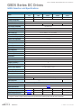
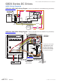
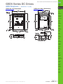
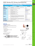
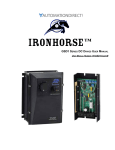
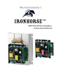
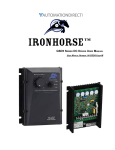
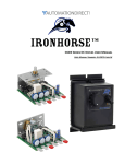
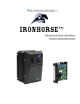
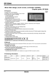
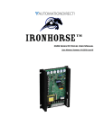
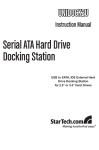
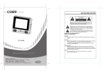
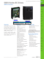
GSD5 Series DC Drives
Prices as of April 16, 2014. Check Web site for most current prices.
Company
Information
GSD5 Introduction
Drives
Soft Starters
Motors
Power
Transmission
Motion: Servos
and Steppers
Motor Controls
Sensors:
Proximity
Sensors:
Photoelectric
Sensors:
Encoders
GSD5-240-10C
Sensors:
Limit Switches
GSD5-240-10N4-x
Sensors:
Current
GSD5 Series DC Drives
Motor Rating Range @ 120/240 VACIN
Overview
IronHorse GSD5 series DC drives offer
superb flexibility, reliability, and value.
A general purpose, economical line of
drives rated to 2 horsepower, it provides
the ultimate in standard features and
versatility, offered in open-frame and
NEMA 4/12 enclosed models.
A logical, easily-accessible layout
simplifies installation and adjustment.
Clean design, quality components and
careful assembly are trademarks of
IronHorse GSD DC drives.
1/8 – 2 hp
Features
• Dual input voltage – 120/240 VAC,
50/60Hz
• Adjustable horsepower settings
• Barrier terminal strip
• Packaged bridge supply (full wave)
• 1% speed regulation with armature
voltage feedback (±1/2% with tach
feedback)
• Adjustable minimum speed
• Adjustable maximum speed
• Adjustable IR compensation
• Adjustable linear acceleration
• Adjustable current limit
• Line voltage compensation
• 5kΩ speed potentiometer with leads,
knob, and dial included
• Power on/off switch (enclosed models)
• 50:1 speed range
• Overload capacity: 150% for one minute
• Transient voltage protection
• Voltage following mode or DC tachometer
follower by supplying ungrounded
analog input signal
• DC tachometer feedback
• Inhibit circuit – permits start and stop
without breaking AC lines
• Remote start/stop via pot circuit or
inhibit circuit
• Shunt field supply provided
• AC line fuse
• Enclosed models rated NEMA 4/12 with
threaded conduit holes
w w w. a u t o m a t i o n d i r e c t . c o m / d r i v e s
Sensors:
Pressure
Accessories
• Replacement speed potentiometer kit
• Digital potentiometer
• Manual reverse switch
• Analog current input card
• Analog voltage input card
Detailed descriptions and specifications for GSD
accessories are available in the “GSD Series DC
Drives Accessories” section.
Typical Applications
• Auger feeders
• Automated door actuators
• Commercial cooking equipment
• Commercial lift
• Food production
• Industrial pumping systems
• Measurement instruments
• Miniature lathes and mills
• Packaging / material-handling equipment
• Printing and labeling machines
• Small shop machine tools
• Spray / print reciprocating head
Sensors:
Temperature
Sensors:
Level
Sensors:
Flow Switches
Pushbuttons
and Lights
Stacklights
Signal
Devices
Process
Relays and
Timers
Pneumatics:
Air Prep
Pneumatics:
Directional Control
Valves
Pneumatics:
Cylinders
Pneumatics:
Tubing
Pneumatics:
Air Fittings
Appendix
Book 2
Terms and
Conditions
Book 2 (14.1)
DC Drives
eDR-113
Prices as of April 16, 2014. Check Web site for most current prices.
GSD5 Series DC Drives
GSD5 Selection and Specifications
GSD5 Series DC Drives – Selection & Specifications
Model
GSD5-240
-10C
GSD5-240
-10N4
GSD5-240
-10N4-A
GSD5-240
-10N4-R
GSD5-240
-10N4-V
Price
$135.00
$175.00
$245.00
$262.00
$265.00
manual reversing
voltage follower
Package Configuration
open frame
NEMA 4/12
Power Quality Form Factor
1.4
Special Features
none
current follower
Input Voltage (@50/60Hz)
120/240 VAC ±10%
Output Voltage
0–90/180 VDC
Shunt Field Voltage
100VDC @ 120VAC input ; 200VDC @ 240VAC input ; (1A max)
Motor Rating (hp)
1/8 – 1 hp @ 90VDC ; 1/4 – 2 hp @ 180VDC
Output Current (continuous)
150mA – 10.8A (DC)
Current Overload Capacity
150% for 60s
Current Limit (adjustable)
1–15A (DC)
Transient Protection
Metal Oxide Varistor (MOV)
I.R. Compensation
adjustable
Speed Adjustment
5kΩ 2W potentiometer or 0–10VDC isolated input signal
Speed Range
50:1
Speed Regulation
±1% of base speed (0.5% with tachometer feedback)
Maximum Speed
adjustable from 66% to 110% of base speed
Minimum Speed
linear ramp 0–30% of adjustable maximum speed
Acceleration
linear ramp adjustable 0.5–8s
Deceleration
adjustable 0.06–80s (dependent on acceleration time setting)
Dynamic Braking
no
Plugging Capability **
no
Electrical Connections
barrier-type terminal strip; 26–12 AWG
Bussman ABC or Littlefuse 314 series ceramic fuses or equivalent
Refer to wiring diagrams for details
External Fusing Required
Operating Temperature
-10 to 45 °C [14 to 113 °F]
Thermal Protection
current limiting
Mounting Orientation
can be mounted in any orientation
Corrosive Gases
Weight
NOT compatible with any corrosive gases
16.25 oz [413g]
Agency Approvals
25.50 oz [723g]
CULUS
listed (E333109), RoHS
RoHS
Optional Accessories *
Replacement Potentiometer
GSDA-5K
Digital Potentiometer
GSDA-DP
Manual Reverse Switch
GSDA-MREV
–
–
included
–
Analog Current Input Card
GSDA-AI-A
–
included
–
–
Analog Voltage Input Card
GSDA-AI-V5
–
–
–
included
* For accessories details, refer to the "GSD Series DC Drives Accessories" section.
** Plugging is a method of rapidly changing motor direction by reversing motor armature polarity, while the motor is still running.
Book 2 (14.1)
eDR-114
DC Drives
1 - 8 0 0 - 633 - 0 4 0 5
Prices as of April 16, 2014. Check Web site for most current prices.
GSD5 Series DC Drives
Company
Information
GSD5 Wiring Diagrams
GSD5-240-10C Basic Wiring Diagram – (refer to User Manual for more detailed wiring information)
Min
Max
IR
Accel Comp
Cur
Lim
Drives
Soft Starters
Motors
Power
Transmission
Motion: Servos
and Steppers
Customer Installed
Speedpot
(factory provided
with 8-inch leads)
Motor Controls
Inhibit
Pin P2
orange white
Sensors:
Proximity
Sensors:
Photoelectric
red
field*
motor
armature
Sensors:
Encoders
AC1
AC2
spare
spare
–Field
+Field
–Arm
+Arm
Wiper
Pot Hi
Pot Lo
P1 1 2 3 4 5 6 7 8 9 10 11
Sensors:
Limit Switches
AC input **
chassis
ground
* Field terminals are used for shunt-wound motors only!
Do not connect these terminals when using permanent-magnet motors.
Sensors:
Current
** AC1 terminal is internally fused; AC2 terminal is NOT internally fused.
Add external fuse for AC2 if it is connected to a hot AC line.
Sensors:
Pressure
GSD5-240-10N4 Basic Wiring Diagram – (refer to User Manual for more detailed wiring information)
Sensors:
Level
FACTORY PREWIRING
Min
Max
IR
Accel Comp
HI (white)
WIPER (red)
LO (orange)
Cur.
Lim.
Sensors:
Flow Switches
Pushbuttons
and Lights
DPST SWITCH
SPEEDPOT
(white
or
yellow)
Stacklights
(black)
Signal
Devices
(white)
(black
or brown)
Process
Relays and
Timers
Inhibit P2
Pin
Pneumatics:
Air Prep
INSIDE OF COVER
Pneumatics:
Directional Control
Valves
Switched AC1
Switched AC2
AC
-Field
AC
+Field
+Arm
Pot Hi
-Arm
Wiper
Pot Lo
P1 -1 -2 -3 -4 -5 -6 -7 -8 -9 -10 -11
Pneumatics:
Cylinders
Pneumatics:
Tubing
Pneumatics:
Air Fittings
CUSTOMER WIRING
chassis
ground
Sensors:
Temperature
field*
motor
armature
ac input**
Endplate with holes for 1/2" NPT conduit
* Field terminals are used for shunt-wound motors only!
Do not connect these terminals when using
permanent-magnet motors.
** AC1 terminal is internally fused; AC2 terminal is NOT
internally fused. Add external fuse for AC2 if it is
connected to a hot AC line.
Appendix
Book 2
Terms and
Conditions
Book 2 (14.1)
w w w. a u t o m a t i o n d i r e c t . c o m / d r i v e s
DC Drives
eDR-115
Prices as of April 16, 2014. Check Web site for most current prices.
GSD5 Series DC Drives
GSD5 Wiring Diagrams
GSD5-240-10N4-A Basic Wiring Diagram – (refer to User Manual for more detailed wiring information)
BALANCE
ADJUSTMENT
LINEARITY/GAIN
ADJUSTMENT
RED
AUTO
125
CURRENT
SOURCE
3PDT
SWITCH
JU2
JU1
JU3
MANUAL
P16
+
-
AC AC
250/500
-1
-2
-3
-4
-5
-6
-7
-8
-9 -10 -11 P1
(GSD5 TERMINAL STRIP)
from P1-2 of GSD5
YELLOW
WHITE
HI
SPEEDPOT
W
RED
LO
ORANGE
GSD5-240-10N4-V Basic Wiring Diagram – (refer to User Manual for more detailed wiring information)
FACTORY PREWIRING
Min
Max
Accel
IR
Comp
Cur.
Lim.
NOTE: SOME
FACTORY WIRING
IS NOT SHOWN
FOR CLARITY
3PDT Switch
(yellow)
(brown)
Speedpot
(red) (white)
(black)
(orange)
(white)
(black)
P2
(brown)
Inhibit
Pin
(red)
P2
Vin or 4-20mA
CONNECTOR
(white)
(white)
(orange)
RANGE
JUMPER
CONNECTOR*
(yellow)
Switched AC
AC
Switched AC
AC
-Field
+Arm
+Field
Wiper
Pot Hi
-Arm
Pot Lo
P1 -1
-1 -2 -3 -4 -5 -6 -7 -8 -9 -10 -11
BALANCE
TRIMPOT
JP2
P4
4-20 Vin
-1 -2 -3
(blue)
GAIN
TRIMPOT
* Jumper clip is used to select
input voltage range. When
installed from P4-1 to P4-2,
the range is 0–25 VDC thru
0–250 VDC. When installed
from P4-2 to P4-3, the range
is 0–5 VDC thru 0–25 VDC.
P3
P5
GSD5-240-10N4-V
(INSIDE OF COVER)
CUSTOMER WIRING
INPUT IMPEDANCE:
motor
ac input
1.2MW on high scale
150KW on low scale
analog
speed
common
analog
speed
signal
Book 2 (14.1)
eDR-116
DC Drives
1 - 8 0 0 - 633 - 0 4 0 5
GSD5 Series DC Drives
GSD5 Dimensions –
Prices as of April 16, 2014. Check Web site for most current prices.
Company
Information
dimensions = in [mm]
GSD5-240-10C Dimensions
Drives
GSD5-240-10N4-x Dimensions
Soft Starters
Motors
Power
Transmission
Motion: Servos
and Steppers
Motor Controls
Sensors:
Proximity
Sensors:
Photoelectric
Sensors:
Encoders
Sensors:
Limit Switches
Sensors:
Current
Sensors:
Pressure
Sensors:
Temperature
Sensors:
Level
Sensors:
Flow Switches
Pushbuttons
and Lights
Stacklights
Signal
Devices
Process
Relays and
Timers
Pneumatics:
Air Prep
Pneumatics:
Directional Control
Valves
Pneumatics:
Cylinders
Pneumatics:
Tubing
Pneumatics:
Air Fittings
Appendix
Book 2
Terms and
Conditions
Book 2 (14.1)
w w w. a u t o m a t i o n d i r e c t . c o m / d r i v e s
DC Drives
eDR-117