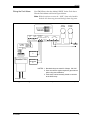
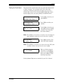
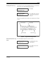
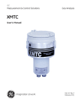
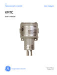
1
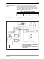
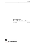
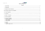
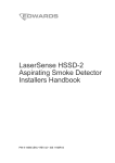
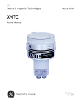
10/2/00
TMO2D with Fault
Alarm and Event Log
Your TMO2D oxygen analyzer has been modified to provide a Fault
Alarm relay contact and an Event Log. However, before you can
access these features, the TMO2D must be installed and programmed
as instructed in your basic User’s Manual.
Depending on the specific software version installed in your unit, the
details for using the Fault Alarm and Event Log differ somewhat.
After verifying your software version, proceed directly to one of the
following sections:
•
Software Version 4B or earlier - go to the section below
•
Software Version 4C or later - go to the section on page 7
Software Version 4B
(or Earlier)
If the software installed in your analyzer is Version 4B or earlier,
proceed with this section. However, if software Version 4C or later is
installed in your analyzer, skip this section and proceed directly to the
section on page 7.
Using the Fault Alarm
The Fault Alarm relay is energized during normal operation. If a fault
or a power failure occurs, the relay is de-energized. This is known as
failsafe operation. The relay has Form-C contacts, so that a fault can
be indicated with either an open contact or a closed contact.
The failsafe Fault Alarm trips when one or more of the following
fault events occurs:
•
power failure
•
RAM checksum failure (memory corruption)
•
transmitter under range
•
transmitter over range
•
no calibration curve
The TMO2D indicates a fault event by de-energizing the relay. If
multiple faults occur simultaneously, the TMO2D indicates the fault
from highest precedence (power failure) to lowest (no calibration
curve), in the order listed above. When all fault conditions have been
removed, the fault relay is re-energized.
Faults are detected only when the TMO2D is in Operate Mode
(displaying data). When in Menu Mode (during programming), the
detection and signaling of faults is suspended. In this case, the Fault
Alarm holds its last state (energized or de-energized) until the unit has
been returned to Operate Mode.
913-220B
1
10/2/00
Using the Fault Alarm
(cont.)
To provide power-failure detection, the Fault Alarm relay is
energized (ON) during normal operation and de-energized (OFF)
during a fault condition. Therefore, when testing the alarm relay,
select “ON” to indicate a normal operating condition and “OFF” to
indicate a fault condition (see Table 1 below).
Table 1: Fault Alarm Relay Conditions
Condition
Alarm State
Alarm Test Selection
Wiring the Fault Alarm
normal operation
energized
ON
fault
de-energized
OFF
Your TMO2D uses the relay labeled “CAL” for the Fault Alarm.
Wire the Fault Alarm as shown in Figure 1 below.
HIGH
ALARM
LOW
ALARM
TMO2D
OXYGEN
CELL
RECORDERS
0/4-20MA
AUTOCAL
RECA RECB PROCESS
IN2
IN1
RTN
+24V
COMP
DX
RTN
+24V
CAL
ALARMS
LOW
HIGH
C NC NO C NC NO C NC NO C NC NO
ALARM
POWER
RED
BLACK
WHITE
BLUE
RED
BLACK
WHITE
BLUE
T-CABLE
237-047
OR EQUAL
SPARE
INPUTS
RECORDER
A
FAULT
ALARM
1 2 3 4
TRANSMITTER
OPTIONAL
RECORDER
B
NOTES: 1. Standard relays are rated for 2 Amps, 120 VAC.
2. User must ensure against explosive gas mixtures
when using auto-calibration.
3. Fault alarm is wired normally-closed to common
at the CAL relay.
OUTLET
INLET
Figure 1: Wiring the TMO2D with Fault Alarm (Software Version 4B or Earlier)
913-220B
2
10/2/00
Testing the Fault Alarm
The Fault Alarm is tested in the same way as the other alarms (refer
to Table 1 on page 2 for a summary of the Fault Alarm relay
conditions). Follow the instructions in Chapter 4 of your User’s
Manual under Alarms Test to enter the [Alarms Test] menu. Notice
that the display below now shows [fault] as an additional choice.
Select alarm to test:
[HIGH]
low fault
done
Use the [NO] or arrow keys to
select [FAULT].
done
Press [YES] to confirm your
selection.
Select alarm to test:
high
low [FAULT]
Turn Fault Alarm:
[ON]
off
done
Use the [NO] or arrow keys to
select [ON]. Then press [YES]
to turn the Fault Alarm ON
(non-fault condition).
Note: When [YES] is pressed above, the alarm relay turns ON (nonfault condition), and the selection brackets move to [OFF].
Turn Fault Alarm:
on
[OFF]
done
Press [YES] to turn the Fault
Alarm OFF (fault condition).
Note: When [YES] is pressed above, the alarm relay turns OFF (fault
condition), and the selection brackets move to [ON].
Turn Fault Alarm:
on
off
[DONE]
When you finish testing the
Fault Alarm, use the [NO] or
arrow keys to select [DONE].
Then, press [YES] to exit the
Fault Alarm test menu.
Exit the [Alarms Test] menu as described in your User’s Manual.
913-220B
3
10/2/00
Using the Event Log
Your modified TMO2D maintains an Event Log in battery-backed
memory. Among other things, this log indicates the nature of any fault
signaled by the Fault Alarm relay by recording the type, date, and
time of the relevant events.
The Event Log can record up to 25 events of the following types:
•
factory initialization
•
system power on
•
system RESET
•
RAM checksum failure (memory corruption)
•
transmitter under range
•
transmitter over range
•
no calibration curve
•
return to normal operation
Note: Testing the Fault Alarm does not appear in the Event Log.
The TMO2D stores only the 25 most recent events in its memory.
When additional events occur, the TMO2D discards the oldest event
from the log to make room for the new event.
913-220B
4
10/2/00
Viewing the Event Log
The Event Log may be viewed on the TMO2D display or transmitted
to a computer, printer or other data acquisition system via the RS232
serial port. To view the Event Log on the TMO2D display, press [NO],
and the following prompt appears:
Enter Code: ***
50.0%
Alarm:
MAIN MENU
Using the keypad, enter the
system passcode (123). An
asterisk is displayed as each
digit is entered.
Setup?
Press [NO] until the System
Log? prompt appears.
MAIN MENU
Press [YES].
System Log?
SYSTEM LOG MENU
Press [NO] until the Display
System Log? prompt appears.
Then, press [YES].
Display System Log?
03: Normal Operation:
04/04/1997
The most recent event in the
Event Log is displayed.
10:21:58
At the above prompt, use the arrow keys to scroll through the logged
events ([←] for the previous event, [→] for the next event). When
done, press [NO] to exit the Event Log. See Figure 2 below for a
description of the components of the event log screen.
Event Number (0-24)
Type of Event
03: Normal Operation:
10/02/2000 10:21:58
Date of Event
Time of Event
Figure 2: The Event Log Display Screen
913-220B
5
10/2/00
Printing the Event Log
To print the Event Log, enter the [System Log] menu, as described in
the previous section. The following display appears:
SYSTEM LOG MENU
Press [NO].
Display System Log?
SYSTEM LOG MENU
Print System Log?
Press [YES] and the entire log
is transmitted via the RS232
serial port.
The Event Log printout looks similar to the example shown in Figure
3 below.
Event Number
Event Date
00: Factory Init at: 10/02/2000 09:34:32
01: Cell Under Range at: 10/02/2000 09:34:33
02: No Calibration at: 10/05/2000 10:14:44
03: Normal Operation: 10/05/2000 10:21:58
Event Type
Event Time
Figure 3: A Typical Event Log Printout
Exiting the [System Log]
Menu
To exit the [System Log] menu, proceed as follows:
SYSTEM LOG MENU
Print System Log?
SYSTEM LOG MENU
Done?
913-220B
Press [NO] until the Done?
prompt appears
Press [YES] to return to the
Main Menu.
6
10/2/00
Software Version 4C
(or Later)
If the software installed in your analyzer is Version 4C or later,
proceed with this section. However, if software Version 4B or earlier
is installed in your analyzer, skip this section and proceed directly to
the section on page 1.
Using the Fault Alarm
The Fault Alarm relay is energized during normal operation. If a fault
or a power failure occurs, the relay is de-energized. This is known as
failsafe operation. The relay has Form-C contacts, so that a fault can
be indicated with either an open contact or a closed contact.
The failsafe Fault Alarm trips when one or more of the following
fault events occurs:
•
power failure
•
RAM checksum failure (memory corruption)
•
transmitter under range
•
transmitter over range
•
no calibration curve
•
AutoCal Total drift
•
AutoCal Drift/Cal
The TMO2D indicates a fault event by de-energizing the relay. If
multiple faults occur simultaneously, the TMO2D indicates the fault
from highest precedence (power failure) to lowest (no calibration
curve), in the order listed above. When all fault conditions have been
removed, the fault relay is re-energized.
Faults are detected only when the TMO2D is in Operate Mode
(displaying data). When in Menu Mode (during programming), the
detection and signaling of faults is suspended. In this case, the Fault
Alarm holds its last state (energized or de-energized) until the unit has
been returned to Operate Mode.
To provide power-failure detection, the Fault Alarm relay is
energized (ON) during normal operation and de-energized (OFF)
during a fault condition. Therefore, when testing the alarm relay,
select “ON” to indicate a normal operating condition and “OFF” to
indicate a fault condition (see Table 2 below).
Table 2: Fault Alarm Relay Conditions
Condition
Alarm State
Alarm Test Selection
913-220B
normal operation
energized
ON
fault
de-energized
OFF
7
10/2/00
Wiring the Fault Alarm
Your TMO2D uses the relay labeled “HIGH” for the Fault Alarm.
Wire the Fault Alarm as shown in Figure 4 below.
Note: With this software version, the “LOW” alarm relay handles
both the low alarm trip point and the high alarm trip point.
FAULT
ALARM
HI-LOW
ALARM
TMO2D
OXYGEN
CELL
AUTOCAL
CAL
ALARMS
LOW
HIGH
IN2
IN1
RTN
C NC NO C NC NO C NC NO C NC NO
ALARM
POWER
RED
BLACK
WHITE
BLUE
RED
BLACK
WHITE
BLUE
RECORDERS
0/4-20MA
RECA RECB PROCESS
+24V
COMP
DX
RTN
+24V
T-CABLE
237-047
OR EQUAL
SPARE
INPUTS
RECORDER
A
1 2 3 4
TRANSMITTER
OPTIONAL
RECORDER
B
NOTES: 1. Standard relays are rated for 2 Amps, 120 VAC.
2. User must ensure against explosive gas mixtures
when using auto-calibration.
3. Fault alarm is wired normally-closed to common
at the HIGH relay.
OUTLET
INLET
Figure 4: Wiring the TMO2D with Fault Alarm (Software Version 4C or Later)
913-220B
8
10/2/00
Testing the Fault Alarm
The Fault Alarm is tested in the same way as the other alarms (refer
to Table 2 on page 7 for a summary of the Fault Alarm relay
conditions). Follow the instructions in Chapter 4 of your User’s
Manual under Alarms Test to enter the [Alarms Test] menu. Notice
that the display below now shows [fault] as an additional choice.
Select alarm to test:
[HI-LOW]
fault
done
Select alarm to test:
hi-low [FAULT]
done
Turn Fault Alarm:
[ON]
off
done
Use the [NO] or arrow keys to
select [FAULT].
Press [YES] to confirm your
selection.
Use the [NO] or arrow keys to
select [ON]. Then press [YES]
to turn the Fault Alarm ON
(non-fault condition).
Note: When [YES] is pressed above, the alarm relay turns ON (nonfault condition), and the selection brackets move to [OFF].
Turn Fault Alarm:
on
[OFF]
done
Press [YES] to turn the Fault
Alarm OFF (fault condition).
Note: When [YES] is pressed above, the alarm relay turns OFF (fault
condition), and the selection brackets move to [ON].
Turn Fault Alarm:
on
off
[DONE]
When you finish testing the
Fault Alarm, use the [NO] or
arrow keys to select [DONE].
Then, press [YES] to exit the
Fault Alarm test menu.
Exit the [Alarms Test] menu as described in your User’s Manual.
913-220B
9
10/2/00
Using the Event Log
Your modified TMO2D maintains an Event Log in battery-backed
memory. Among other things, this log indicates the nature of any fault
signaled by the Fault Alarm relay by recording the type, date, and
time of the relevant events.
The Event Log can record up to 25 events of the following types:
•
factory initialization
•
system power on
•
system RESET
•
RAM checksum failure (memory corruption)
•
transmitter under range
•
transmitter over range
•
no calibration curve
•
return to normal operation
•
AutoCal Total drift
•
AutoCal Drift/Cal
Note: Testing the Fault Alarm does not appear in the Event Log.
The TMO2D stores only the 25 most recent events in its memory.
When additional events occur, the TMO2D discards the oldest event
from the log to make room for the new event.
913-220B
10
10/2/00
Viewing the Event Log
The Event Log may be viewed on the TMO2D display or transmitted
to a computer, printer or other data acquisition system via the RS232
serial port. To view the Event Log on the TMO2D display, press [NO],
and the following prompt appears:
Enter Code: ***
50.0%
Alarm:
MAIN MENU
Using the keypad, enter the
system passcode (123). An
asterisk is displayed as each
digit is entered.
Setup?
Press [NO] until the System
Log? prompt appears.
MAIN MENU
Press [YES].
System Log?
SYSTEM LOG MENU
Press [NO] until the Display
System Log? prompt appears.
Then, press [YES].
Display System Log?
03: Normal Operation:
04/04/1997
The most recent event in the
Event Log is displayed.
10:21:58
At the above prompt, use the arrow keys to scroll through the logged
events ([←] for the previous event, [→] for the next event). When
done, press [NO] to exit the Event Log. See Figure 5 below for a
description of the components of the event log screen.
Event Number (0-24)
Type of Event
03: Normal Operation:
10/02/2000 10:21:58
Date of Event
Time of Event
Figure 5: The Event Log Display Screen
913-220B
11
10/2/00
Printing the Event Log
To print the Event Log, enter the [System Log] menu, as described in
the previous section. The following display appears:
SYSTEM LOG MENU
Press [NO].
Display System Log?
SYSTEM LOG MENU
Print System Log?
Press [YES] and the entire log
is transmitted via the RS232
serial port.
The Event Log printout looks similar to the example shown in Figure
6 below.
Event Number
Event Date
00: Factory Init at: 10/02/2000 09:34:32
01: Cell Under Range at: 10/02/2000 09:34:33
02: No Calibration at: 10/05/2000 10:14:44
03: Normal Operation: 10/05/2000 10:21:58
Event Type
Event Time
Figure 6: A Typical Event Log Printout
Exiting the [System Log]
Menu
To exit the [System Log] menu, proceed as follows:
SYSTEM LOG MENU
Print System Log?
SYSTEM LOG MENU
Done?
913-220B
Press [NO] until the Done?
prompt appears
Press [YES] to return to the
Main Menu.
12