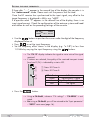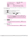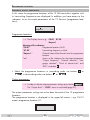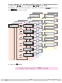
1
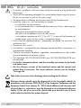
Head-End Modulator FM 2xSAT+ASI to 12xFM KLASSE HDTV 1000 FM English CLASS GSS Grundig SAT Systems GmbH Beuthener Strasse 43 D-90471 Nuremberg Phone: Fax: E-mail: Internet: +49 (0) 911 / 703 8877 +49 (0) 911 / 703 9210 [email protected] http://www.gss.de Contents 1 Safety regulations and notes............................................................................... 3 2 General information........................................................................................... 4 2.1 Packing contents................................................................................. 4 2.2 Meaning of the symbols used................................................................ 4 2.3 Technical data.................................................................................... 4 2.4 Description......................................................................................... 6 2.5 Software query................................................................................... 7 3 Assembly........................................................................................................... 8 3.1 Installing the cassette........................................................................... 8 3.2 EMC regulations................................................................................. 9 3.3 Cassette overview............................................................................. 10 3.4 Connecting the cassette...................................................................... 10 3.5 Retrofitting a CA module.................................................................... 11 4 The control panel at a glance............................................................................ 12 4.1 Menu items....................................................................................... 12 4.2 Control panel.................................................................................... 12 5 Programming................................................................................................... 13 5.1 Programming procedure..........................................................................13 5.2 Programming the cassette................................................................... 15 Selecting the cassette......................................................................... 15 Input parameters............................................................................... 16 LNB oscillator frequency............................................................... 16 Input symbol rate......................................................................... 17 DVB mode.................................................................................. 17 Setting the input frequency............................................................ 18 Operation with a CA module........................................................ 19 PID monitoring............................................................................. 19 CA module.................................................................................. 19 Delete programme locations............................................................... 21 Programme locations......................................................................... 22 Submenus output parameters.............................................................. 22 Output frequency......................................................................... 24 Channel selection......................................................................... 24 Language selection....................................................................... 25 Frequency deviation adjustment..................................................... 25 Kind of transmission..................................................................... 26 RDS............................................................................................ 26 Output level...................................................................................... 27 Factory reset..................................................................................... 28 Saving settings.................................................................................. 28 6 Final procedures............................................................................................... 29 - 2 - HDTV 1000 FM 1S a f e t y regulations and notes • Assembly, installation and servicing should be carried out by authorised electricians. • Switch off the operating voltage of the system before beginning with assembly or service work or pull out the mains plug. • Do not perform installation and service work during thunderstorms. • Install the system so it will not be able to vibrate… - in a dust-free, dry environment - in such a manner that it is protected from moisture, fumes, splashing water and dampness - somewhere protected from direct sunlight - not within the immediate vicinity of heat sources - in an ambient temperature of 0 °C to +50 °C. In case of the formation of condensation wait until the system is completely dried. • Ensure that the head-end station is adequately ventilated. Do not cover the ventilation slots. • Beware of short circuits • No liability is accepted for any damage caused by faulty connections or inappropriate handling. • Observe the relevant standards, regulations and guidelines on the installation and operation of antenna systems. • The standards IEC/EN/DIN EN 50083 resp. IEC/EN/DIN EN 60728 must be observed. • For further information please read the assembly instructions for the headend station used. • Test the software versions of the head-end station and the cassette and update them if necessary. The current software versions can be found at "www.gss.de". Take action to prevent static discharge when working on the device! Electronic devices should never be disposed of in the household rubbish. In accordance with directive 2002/96/EC of the European Parliament and the European Council from January 27, 2003 which addresses old electronic and electrical devices, such devices must be disposed of at a designated collection facility. At the end of its service life, please take your device to one of these public collection facilities for proper disposal. - 3 - HDTV 1000 FM 2G e n e r a l 2.1 Pac k i n g contents 1 Cassette HDTV 1000 FM 1 Brief assembly instructions 2.2M e a n i n g 2 HF cables o f t h e s ym b o l s u s e d Important note —> General note • Performing works 2.3T e c h n i c a l information data The devices meet the following EU directives: 2006/95/EC, 2004/108/EC The product fulfils the guidelines and standards for CE labelling (see page 30). Unless otherwise noted all values are specified as "typical". HF Input Frequency range......................................................... 925 … 2150 MHz Level range.............................................................. 60 dBμV … 80 dBμV Input impedance.............................................................................. 75 Ω DVB-S modes........................................... QPSK 1/2, 2/3, 3/4, 5/6, 7/8 DVB-S2 modes................QPSK 1/2, 3/5, 2/3, 3/4, 4/5, 5/6, 8/9, 9/10 8PSK 3/5 , 2/3 , 3/4 , 5/6 , 8/9 , 9/10 Symbol rate DVB-S.............................................. QPSK: 2 … 45 MSymb/s Symbol rate DVB-S2.......................................... QPSK: 10 … 30 MSymb/s 8PSK: 10 … 31 MSymb/s HF output Frequency range........................................... 87.50 MHz … 108.00 MHz Tuning steps................................................................................. 50 kHz Type of modulation............................................................................. FM Return loss.......................................................................................8 dB Output level............................................................................... 93 dBμV Signal-to-harmonics ratio...............................................................>60 dB - 4 - HDTV 1000 FM Output impedance........................................................................... 75 Ω External voltage difference Mono.........................................................................................66 dB Stereo........................................................................................53 dB Non-linear distortion factor Mono........................................................................................ 0,06% Stereo......................................................................................... 0,6% Overall output frequency deviation................................................. 75 kHz FM modulator Number of available services (programme locations)...............................12 RDS signal processing...................................................................................57 kHz Pilot signal...................................................................................................19 kHz Preemphasis................................................................................................... 50 μs ASI-Schnittstelle Standard.........................................................................DIN EN 50083-9 Format................................................................MPEG ISO IEC 13818-1 Impedance....................................................................................... 75 Ω User data rate...................................................................2 … 90 Mbit/s Level....................................................................................... 800 mVPP Return loss..........................................................> 17 dB (5 … 270 MHz) Anschlüsse SAT inputs..............................................................................2 F-Buchsen HF output............................................................................. 1 IEC-Buchse ASI input........................................................................... 1 BNC-Buchse Connection strip............................................................................ 10-pin For supply voltages and control circuits Update interface................................................................ Buchse RS 232 Common Interface.................................................................................1 Several channels can be descrambled Remote maintenance Remotely controllable (via PSW 1000*):............................................... yes Remote update (via BEflash*):.............................................................. yes (* and a corresponding management unit) - 5 - HDTV 1000 FM 2.4D e s c r i p t i o n The cassette converts 12 stereo audio channels from two DVB-S /DVB-S2 standard modulated transponders and the ASI input signal into 12 FM modulated stereo output channels. The RDS station code is automatically taken from the station name of the transponder or can be entered manually. Via SAT input A and a corresponding CA module scrambled channels can be descrambled. Principle signal path: SAT input ”B“ Receiving stage "B" TS B HF output The cassette is controlled with the head-end station control unit. Two LEDs indicate by their colour the quality of the input signals (see figure on page ��� ���� ). LED indicator Green Yellow Red CA module TS ASI ASI input TS A Combiner Receiving stage "A" 12 fold modulator SAT input ”A“ TPS Indication Signal quality is good Signal quality is poor No signal To operate this cassette the software version of the control unit must be "V 44" or higher. You can find the current operating software for the control unit and the cassette, the software "BE-Flash" and the current assembly instructions on the website "www.gss.de". The cassette is designed for use in head-end stations of the standard line. - 6 - HDTV 1000 FM 2.5S o f t wa r e Control unit If necessary, you can activate the indication of the software version of the control unit manually: • Press any two keys on the control unit of the head-end station simultaneously until the display goes dark and the software version, e.g. "V 44" appears. q u e ry Cassette After activating the cassette the software version of the cassette is displayed (see page 15). - 7 - HDTV 1000 FM 3A s s e m b l y 3.1I n s ta l l i n g the cassette – Ensure the head-end station is mounted so it will not be able to vibrate. Avoid, for example, mounting the head-end station onto a lift shaft or any other wall or floor construction that vibrates in a similar way. – Before installing or changing a cassette unplug the power cable from the mains power socket. • Remove the fastening screws 1 of an unoccupied slot from the bracket of the head-end station. • Insert the cassette in this slot and push it into the housing. • Align the cassette and apply slight pressure to connect it to the connections of the board and the HF bus bar. • Fasten the cassette with the screws 1. 1 ACHTUNG! Vor dem Cassettenwechsel unbedingt Netzstecker ziehen! CASSETTE CASSETTE CASSETTE CASSETTE CASSETTE CASSETTE CASSETTE CASSETTE CASSETTE CASSETTE CASSETTE CASSETTE 0° MESSAUSGANG KLASSE CAUTION! Before changing cassettes remove mains plug! A CLASS 1 - 8 - HDTV 1000 FM 3.2 EMC KLASSE CLASS r e g u l at i o n s To comply with the current EMC regulations, it is necessary to connect the lines leading in and out of the head-end station using cable terminals. When mounting the cassette in a head-end station which is installed in a 19" cabinet, make sure the connections leading in and out for the 19" cabinet are made using cable terminals. The attenuation of shielding of the connection lines for ASI and antenna must meet the requirements for "Class A". • Insert the required number of cable terminals in the openings provided in the head-end station or in the 19" cabinet. Tighten the nuts on the cable terminals until the teeth on the lock washer have penetrated the exterior coating and a good connection is made between the housing and cable terminals. - 9 - HDTV 1000 FM 3.3 C a s s e t t e ov e rv i e w 1 2 3 4 5 1 2 3 4 5 6 7 8 9 D-SUB socket "RS 232" Slot for CA module not used ASI input not used SAT input (tuner "A") Status LED of input "A" SAT input (tuner "B") Status LED of input "B" 6 7 The operating software of the cassette can be updated via the 8 9 on the website "www.gss.de". 3.4 C o n n e c t i n g 9-pin D-SUB socket "RS 232" using a PC or notebook and the software "BE-Flash". You can find the current operating software the cassette • Connect the SAT input sockets "A" (tuner "A") and "B" (tuner "B") to the corresponding output sockets of the input distributor. Use a 6dB attenuator for a direct connection without the input distributor. • Connect the ASI socket. • Connect the head-end station to the mains. - 10 - HDTV 1000 FM 3.5R e t r o f i t t i n g a CA module The cassette is equipped with a common interface. It allows you to connect a CA module for various scrambling systems and service providers. Scrambled stations can only be descrambled with a CA module suitable for the scrambling system and the corresponding smart card. The smart card contains all the information for authorisation, descrambling and subscription. Caution – Check with the distributor or manufacturer of the CA module to be used to ensure that it is suitable for descrambling several channels. – Any changes made by programme providers to the structures in the programme data might impair or even prevent this function. – When working with the CA module, please read the corresponding operating manual from the respective provider. • Insert the smart card into the CA module so that the chip 3 on the smart card 1 faces the thicker side (top) of the CA module 2. • Insert the CA module into the slot 4 with the top side of the CA module facing the RS-232 socket of the cassette. • Push the CA module without canting into the guide rails of the CA slot 4 and contact it to the common interface. 4 2 31 - 11 - HDTV 1000 FM 4T h e control panel at a glance 4.1M e n u items Programme the cassette using the buttons on the control unit of the head-end station. The two-line display of the control unit then shows the menus. The parameters and functions to be set are underlined. Use the key to select the following main menu items: – Input parameters – Deleting services (programme locations) – Output parameters – Output level – Factory reset 4.2 C o n t r o l V44 please wait . . . pa n e l The key pad on the head-end station is used to scroll through the menus: scrolls forward through the menus. select parameters in the menus. set values, initiate actions. selects sub-menus. scrolls backward through the menus. saves all entries. BE-Remote - 12 - HDTV 1000 FM 5 Programming 5.1 P ro g r a m m i n g pro c e d u r e Ein / On BE–Remote V 44 please wait … t > 10 s Box … …… ……… …… Box 4 DVBS2-FM V1 Bedienhinweise "blättert" Menüs vorwärts. "blättert" Menüs rückwärts. wählen die Eingabeposition wählt Untermenü stellen Werte ein,. speichert alle Eingaben. 1 zeigt die Eingabeposition Operating Hints scrolls forward through the menu. scrolls backward through the menu. select the enter position. selects a submenu. set values and triggers actions. saves all entries. 1 shows the enter position Bx 1A TWIN-SAT Böx 4 TWIN-SAT Box 5 .............. C5-12,S3-24 C07 C5-12,S3-24 C07 .............. .............. ––– A B Bx 4 INPUT TunerA OK => ▶ Tuner A / Tuner B / ASI Bx 4A/B page 14 LNB 10600 MHz 9750 / 10600 Bx 4A/B SYMBOL DVB-S / QPSK… / 8PSK… / DTV… DVB–S 27500 22000 / 27500 Bx 4A/B 12265 FREQ CN 13 +0.3 Bx 4A CA-MENU PID Check on => nur mit CA-Modul nur Tuner A / only with CA module only tuner A Bx 4 FM SERVICES => CLEAR ALL FM 01 Bayern 1 FM 01…12 FM 12…01 87.50 => ▶ ▶ Bx 4A 01/05 MENU Information *) *) Die angezeigte Information ist abhängig vom verwendeten CA-Modul. The information displayed is dependent on the CA module used. ▶ ▶ FM 01 FREQ 87.50 FM 01…12 FM 12…01 => auto - 13 - FM 01 RA 001/091 HDTV 1000 FM FM 01 Bayern 1 87.50 FM 01 ▶ => FM 01…12 FM 12…01 FREQ 87.50 => auto FM 01…12 FM 12…01 FM 01 RA 001/091 Senderauswahl Station selection Bayern 1 FM 01…12 FM 12…01 FM 01 AUDIO Sprachauswahl Language selection 01/01 ger FM 01…12 FM 12…01 FM 01 VOLUME 0.0 dB Hubanpassung Deviation adjustment <=>C FM 01…12 FM 12…01 FM 01 < = > C zu klein too small OK zu groß too big Begrenzung clipping AUDIO AUTO AUTO / MONO / STEREO FM 01…12 FM 12…01 FM 01 RDS-NAME Bayern 1 => auto FM 01…12 FM 12…01 Bx 4 LEVEL 0 dB 0 … - 10 dB Seite 13 Bx 4 Defaults FACTORY => ▶ Bx 4 FACTORY STORE => M - 14 - auf Werkseinstellung zurücksetzen und speichern M reset to factory defaults and store A B HDTV 1000 FM 5.2 P r o g r a m m i n g the cassette —> Pressing the button for longer than 2 seconds cancels the programming procedure. This takes you back to the program item "Selecting the cassette" from any menu. Any entries that have not been saved are reset to the previous settings. —> Entries in the menus can be saved by pressing the key. You are taken back to the "Selecting the cassette" menu item. —> Pressing the button returns to the previous menus. • Switch on the head-end station Ein / On BE–Remote V 44 please wait … t > 10 s —> The display shows the software version (e.g. V 44) —> The processor reads the cassettes‘ data (approx. 10 seconds). S e l e c t i n g the cassette Box … …… ……… …… Box 4 DVBS2-FM V1 Bx 1A TWIN-SAT Böx 4 TWIN-SAT Box 5 .............. C5-12,S3-24 C07 C5-12,S3-24 C07 .............. .............. ––– • Select the cassette you want to program (e.g. Box 4) by repeatedly pressing the button if necessary. —> The display shows e.g. the menu "Box 4 DVBS2-FM": "Box 4" stands for slot 4, "DVBS2-FM" type of cassette "V 1" software version of the cassette • Press the button. —> The "Input parameters" – "INPUT" main menu is activated. - 15 - HDTV 1000 FM I n p u t pa r a m e t e rs In this menu you select the input, for which you would like to set the input parameters in the submenus. Bx 4 INPUT TunerA OK => —> The indication "OK" serve for information: OK - input signal is present at tuner A. • Use the buttons to select the input ("Tuner A" / "Tuner B" / "ASI"), for which you would like to set the input parameters. —> There are no input parameter settings for the ASI input. Select "ASI", in order to check whether a ASI input signal is present ("OK" is displayed). —> To skip the settings of the input parameters press the button. The "Delete programme locations" – "SERVICES" main menu is activated (page 21). • Press the button. —> The "LNB oscillator frequency" – "LNB" submenu is activated. LNB os c i l l ato r f r e q u e n c y Set the oscillator frequency of the LNB used in this menu. Bx 4A/B LNB 10600 MHz • Using the button the oscillator frequencies "10600" or "9750" can be selected directly. • To set other oscillator frequencies use the buttons to place the cursor under the digit of the oscillator frequency displayed to be set. • Press to enter the respective digit of the oscillator frequency of the LNB used. • Repeat the procedure by the quantity of the digits to be set. - 16 - HDTV 1000 FM • Press the button. —> The "Input symbol rate, DVB mode" – "SYMBOL" menu is activated. I n p u t DVB s ym b o l r at e mode The symbol rates of the satellite transponders can be found in the current channel table of the satellite operator, in various satellite magazines and in the Internet. The cassette recognizes the transmitted DVB mode and switches over between the normal QPSK mode (DVB-S) and the DVB-S2 mode. Receiving stations with DVB-S2 mode, we suggest to preset the DVB mode manually to shorten the time for searching stations. Bx 4A/B 27500 SYMBOL DVB–S Setting the input symbol rate • Using the button the symbol rates 27500" or "22000" can be selected directly. • To set other symbol rates use the buttons to position the cursor under the digit of the symbol rate displayed to be set. • Press to enter the respective digit of the symbol rate needed. • Repeat the procedure by the quantity of the digits to be set. Setting the DVB mode • Use the button to place the cursor under "DVB-S" and set the required DVB-S2-mode with the buttons. • Press the button. —> The "Setting the input frequency" – "FREQ" menu is activated. - 17 - HDTV 1000 FM S e t t i n g the input frequency If three dots " … " appear in the second line of the display, the cassette is in the "station search" mode. Please wait until the process has finished. Once the HF receiver has synchronised to the input signal, any offset to the target frequency is displayed in MHz, e.g. "+0.3". If a question mark "?" appears in the second line of the display, there is no input signal present. Check the configuration of the antenna system and headend station as well as the preceding settings of the cassette. Bx 4A/B 12265 FREQ +0.3 CN 13 • Use the buttons to position the cursor under the digit of the frequency displayed to be set. • Press to set the1 input frequency. • Set the frequency offset shown in the display (e.g. "+ 1.3") to less than 2 input frequency using the 1.0 MHz by varying the buttons. —> The "CN 13" display indicates the signal to noise ratio of the signal 3 received. —> If stations4 are selected, the quality of the received transport stream (level and5 C/N) is indicated by a status LED. 6 7 Status LED Tuner A 7 9 Status LED Tuner B 8 9 LED indicator Green Yellow Red • Press the Indication Signal quality is good Signal quality is insufficient No signal button. —> Using a CA-Modul, submenu "CA settings" – "CA-MENU" is activated. —> Not using a CA-Modul you will be returned to the "Input parameter" – "INPUT" main menu (page 16). - 18 - HDTV 1000 FM O p e r at i o n with a CA module In order to descramble scrambled channels, a corresponding CA module is needed. PID CA In this menu you can switch off the PID monitoring and configuring the CA module (dependent on the CA module). m o n i to r i n g module Bx 4A CA-MENU PID Check on PID monitoring By default the PID monitoring is switched on. If particular PIDs are not descrambled the CI module is reset. Additionally dropouts may occur if several stations are descrambled. To prevent this the PID monitoring can be switched off. Bx 4A CA-MENU PID Check on => • Use the buttons to switch "off" or "on" the PID monitoring. Configuring the CA module • Use the The menu varies according to which CA module you are using. For this reason, please refer to the operating manual of your particular CA module. The relevant information is shown in the display of the head-end station. This may appear as a fixed display or as scrolling text according to display capabilities. button to activate the menu of the CA module. Bx 4A CA-MENU PID Check on => => ▶ ▶ - 19 - Bx 4A 01/05 MENU Information *) HDTV 1000 FM —> The display shows e.g.: Bx 4 01/05 MENU Information Meaning of the indicators: "Bx 4" Slot 4 "01/05" The first of five menu items is activated. "MENU" The menu of the CA module is activated. For the explanation of further details please use the operating instructions of the CA module used. • Use the buttons to activate the menu desired. • Press the button to activate the menu. • Use the buttons to select the function desired. • To set the CA module use the and buttons. • All settings are saved by pressing the button. —> You will be returned to the "PID monitoring" – "CA" main menu. —> By pressing the button you can cancel the settings in the menu of the CA module and are returned to the "PID monitoring" – "CA" main menu. • Press the button. —> You will be returned to the "Input parameter" – "INPUT" main menu (page 16). • Press the button. —> The menu "Delete programme locations" – "SERVICES" is activated. - 20 - HDTV 1000 FM D e l e t e p r o g r a m m e lo c at i o n s In this menu you can delete the programme locations preset in the factory resp. "old" programme locations (e.g. if the input parameter setting was changed). Bx 4 FM SERVICES => CLEAR ALL • Delete the programme locations using the button. —> All programme locations are deleted, the stored FM frequencies will be remain. As long as no radio station is assigned to a programme location, the transmitter is switched off. —> A "Factory Reset" resets to the programme locations preset in the factory. • Press the button. —> The "Output parameters" – "FM 01" menu is activated. - 21 - HDTV 1000 FM Progr a mme S u b m e n u s lo c at i o n s o u t p u t pa r a m e t e rs In this menu the programme locations of the 12 FM transmitters together with its transmitting frequencies are displayed. In addition you have access to the submenus to set the output parameters of the 12 Services (programme locations). FM 01 87.50 Bayern 1 => Programme locations: —> The Display shows e.g.: FM 01 87.50 Bayern 1 Meaning of the indicators: "FM 01" Programme location FM 01 "87.50" Transmitting frequency in MHz "Bayern 1" Channel name of the channel set to this programme location. "=>" Access to the submenus for the output parameters "Output frequency", "channel selection", "Language selection", "Kind of transmission" and "RDS" via button • Select the programme locations in ascending order via buttons , in descending order via buttons or . Output parameters: or —> In order to skip the output parameter settings press button The "Output level" – "LEVEL" menu os activated (page 27). The output parameter settings are to be done for each of the 12 programme locations. The programme location is displayed in the upper left corner – e.g. FM 01 means programme location 01. FM 01 . - 22 - HDTV 1000 FM In every submenu it is possible to rotate through the 12 programme locations using buttons (ascending) and (descending). Navigation between the submenus is possible via buttons (next menu) and (previous menu). FM 01 FM 12 87.50 87.50 => FM 01 FREQ FREQ=> auto FM 12 => => auto FM 01 RA FM 04 FM 03 FM 02 FM 01 87.50 87.50 87.50 Bayern 1 => 87.50 => => => ▶ FM 04 FM 01…12 87.50 => auto FM 12 AUDIO FM 01 FM 04 FM 02 AUDIO AUDIO VOLUME AUTO AUTO VOLUME VOLUME 0.0 dB VOLUME VOLUME AUDIO AUDIO FM 01 <=>C FM 04 FM 03 AUDIO AUDIO RDS-NAME RDS-NAME=> auto FM 12 AUTO => auto AUDIO AUTO FM 02 AUDIO AUTO FM 01 AUTO FM 01…12 FM 03 FM 02 FM 01 FM 01…12 VOLUME FM 01 FM 03 FM 12…01 FM 12 FM 04 01/01 ger FM 12…01 AUDIO AUDIO AUDIO 001/091 FM 03 FM 01 FM 01…12 FM 12 001/091 FM 02 FM 12…01 001/091 001/091 Bayern 1 FM 01 FM 01…12 FM 01 FM 04 RA FM 03 RA FM 02 RA FM 01 RA 001/091 001/091 FREQ=> auto FREQ=> auto FM 01 FM 12…01 FM 12 RA FREQ=> auto FM 03 FM 02 FM 01…12 FM 12…01 FREQ Bayern 1 FM 04 RDS-NAME RDS-NAME=> auto RDS-NAME=> auto RDS-NAME=> auto => auto FM 12…01 • Press the button. —> Submenu "Output frequency" – "FREQ" is activated. - 23 - HDTV 1000 FM O u t p u t frequency In this submenu set the output frequencies of the programme locations. FM 01 FREQ 87.50 => auto • Use the buttons to place the cursor under the digit to be set for the frequency display then use to set the output frequency wished. —> Via the "auto" function it is possible to set the output frequencies of the following programme locations automatically in 300 kHz steps - from the displayed programme location on. "auto" function: • Press the button. —> The output frequencies of the following programme locations are set automatically. • Press the button. —> The "Channel selection" – "001/xxx" submenu is activated. Channel In this menu you assign which of the channels available (via tuner A, tuner B and ASI) is transmitted via the corresponding programme location. selection FM 01 RA 001/091 Bayern 1 Meaning of the indicators: "FM 01" Programme location FM 01 "RA" Radio channel "001/091" Channel 1 of 91 "Bayern 1" Programme name of channel 1. - 24 - HDTV 1000 FM • Use the buttons to select the channel wished. —> To switch off the modulator of a programme location the channel selection must be set to "000". —> Indication FM 01 –––/091 As long as no radio station is assigned to a programme location, the transmitter is switched off. • Press the button. —> The "Language selection" – "AUDIO" submenu is activated. L a n g uag e selection If more than one languages are available, in this submenu select the language wished (e.g. language 1 of 1 - German). FM 01 AUDIO 01/01 ger • Use the • Press the buttons to select the language wished. button. —> The "Frequency deviation adjustment" – "VOLUME" submenu is activated. F r e q u e n c y d e v i at i o n a dj u s tm e n t In this submenu you can adjust the deviation. This has effects for the volume. FM 01 0.0 dB • With buttons VOLUME <=>C adjust the frequency deviation in 0.1 dB steps. - 25 - HDTV 1000 FM Meaning of the indicators: "<" Frequency deviation too small "=" Frequency deviation OK ">" Frequency deviation too big "C" Frequency deviation much too big - signal is clipping. • Press the button. —> The "Kind of transmission" – "AUDIO" submenu is activated. K i n d of tr ansmission In this submenu the kind of transmission can be set (stereo/mono/automatic). FM 01 AUDIO AUTO • Use the • Press the buttons to select the kind of transmission wished. button. —> The "RDS" – "RDS-NAME" submenu is activated. RDS In this submenu you can enter the RDS "Programme Service Name" (PS). FM 01 RDS-NAME Bayern 1 • Use the be set. • Press => auto buttons to position the cursor under the digit of the name to to set the respective digit of the name. —> Via the "auto" function you can adopt the RDS Programme Service Name automatically from the channel name of the transponder. - 26 - HDTV 1000 FM "auto" function: • Press the button. —> The RDS Programme Service Name will be adopted automatically from the channel name of the transponder. • Press the button. —> You will be returned to the "Programme location" - "FM 01" main menu. —> If necessary adjust another programme locations —> . • Press the button. —> The "Output level" – "LEVEL" main menu is activated. O u t p u t level In this menu the output level can be adjusted (0 … -10 dB). Bx 4 LEVEL 0 dB • With the • Press the buttons adjust the output level wished. button. —> The "Factory reset" – "FACTORY" main menu is activated. - 27 - HDTV 1000 FM Fac to ry reset In this menu you can reset all settings to the factory defaults. Bx 4 FACTORY Defaults • Press the => ▶ Bx 4 FACTORY STORE => M M button. —> The submenu "FACTORY STORE" is invoked. —> By pressing the button, you will be returned to the menu item "Input parameters" – "INPUT" without invoking the factory defaults (page 16). • Press the button. —> The factory defaults are saved. The display shows "STORE" —> Back to "Selecting the cassette" (page 15). —> By pressing the button, you will be returned to the menu item "Input parameters" – "INPUT" without invoking the factory defaults (page 16). S av i n g • Press the s e t t i n gs button. —> Back to "Selecting the cassette" (page 15). —> The settings are saved. - 28 - HDTV 1000 FM 6F i n a l pro c e d u r es After installing the head-end station, upgrading accessories or installing cassettes it is necessary to tighten all cable connections, cable terminals and cover screws in order to maintain compliance with current EMC regulations securely. • Securely tighten the cable bolted connections using an appropriate openended spanner. • Mount the front cover (see assembly instructions of the head-end station). - 29 - HDTV 1000 FM Declaration of CE conformity - 30 - HDTV 1000 FM Service: Phone: Fax: Email: +49 (0) 911 / 703 2221 +49 (0) 911 / 703 2326 [email protected] Alterations reserved. Technical data E. & O.E. © by GSS GmbH V1/17112010