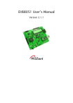
1
[텍스트 입력] WIZ200WEB User’s Manual (Ver. 1.0) ©2007 WIZnet Inc. All Rights Reserved. For more information, visit our website at www.wiznet.co.kr WIZ200WEB User’s Manual Document History Information Revision Ver. 1.0 Data 2008. 12. Description Release with WIZ200WEB launching 2 © Copyright 2007 WIZnet Inc. All rights reserved WIZ200WEB User’s Manual WIZnet’s Online Technical Support If you have any questions or want more information about WIZnet products, submit your question to the Q&A Board on the WIZnet website.(www.wiznet.co.kr) A WIZnet engineer will have an answer for you as soon as possible. 3 © Copyright 2007 WIZnet Inc. All rights reserved WIZ200WEB User’s Manual Table of Contents 1. Introduction ......................................................................................................................................... 7 1.1. Main Function .........................................................................................................................................................7 1.2. Specification ............................................................................................................................................................8 1.3. Contents (WIZ200WEB-EVB) .............................................................................................................................8 2. Block Diagram ..................................................................................................................................... 9 3. WIZ200WEB Base Board .................................................................................................................. 11 4. Getting Started .................................................................................................................................. 16 4.1. 4.1.1. Basic Configuration .................................................................................................................................. 16 4.1.2. Firmware Upload ....................................................................................................................................... 17 4.1.3. Webpage Upload ...................................................................................................................................... 19 4.1.4. Use of Rom File Maker rev3.0.............................................................................................................. 20 4.2. 5. 6. 7. Configuration Tool ............................................................................................................................................. 16 Operation Test ..................................................................................................................................................... 22 4.2.1. Hardware Interface ................................................................................................................................... 22 4.2.2. Testing the Function of Web Server.................................................................................................. 23 Programmer’s Guide ........................................................................................................................ 26 5.1. Memory Map ....................................................................................................................................................... 26 5.2. WIZ200WEB Firmware ................................................................................................................................... 26 5.3. Compile .................................................................................................................................................................. 28 5.4. Downloading ........................................................................................................................................................ 28 WIZ200WEB Hardware Specification ............................................................................................ 31 6.1. Parameters ............................................................................................................................................................ 31 6.2. Specification ......................................................................................................................................................... 31 6.3. Board Dimensions and Pin Assignment ................................................................................................... 31 6.3.1. Pin Assignment .......................................................................................................................................... 31 6.3.2. Size .................................................................................................................................................................. 32 6.3.3. Connector Specification.......................................................................................................................... 33 Warranty ............................................................................................................................................. 35 © Copyright 2007 WIZnet Inc. All rights reserved 4 WIZ200WEB User’s Manual Tables Table 1. WIZ200WEB Specification .................................................................................................................8 Table 2. Contents of WIZ200WEB ...................................................................................................................9 Table 3. WIZ200WEB PIN MAP ..................................................................................................................... 12 Table 4. Expansion Connector ....................................................................................................................... 15 Table 5. WIZ200WEB Testing Environment .............................................................................................. 22 Table 6. WIZ200WEB Main Source .............................................................................................................. 27 Table 7. WIZ200WEB PINMAP....................................................................................................................... 31 © Copyright 2007 WIZnet Inc. All rights reserved 5 WIZ200WEB User’s Manual Figures Figure 1. Block Diagram .................................................................................................................................. 10 Figure 2. WIZ200WEB Base Board Layout ............................................................................................... 11 Figure 3. AVR JTAG Connector...................................................................................................................... 12 Figure 4. AVR ISP Connector ......................................................................................................................... 12 Figure 5. WIZ200WEB PIN MAP ................................................................................................................... 12 Figure 6. WIZ200WEB LED.............................................................................................................................. 13 Figure 7. WIZ200WEB Switch ........................................................................................................................ 13 Figure 8. WIZ200WEB 16x2 LCD .................................................................................................................. 14 Figure 9. WIZ200WEB VR ................................................................................................................................ 14 Figure 10. WIZ200WEB Temperature Sensor .......................................................................................... 15 Figure 11. Configuration Tool ....................................................................................................................... 16 Figure 12. Board Search Window ................................................................................................................ 18 Figure 13. Open dialog box for uploading ............................................................................................. 19 Figure 14. Firmware uploading window ................................................................................................... 19 Figure 15. Complete Uploading ................................................................................................................... 19 Figure 16. Flash Rom Image File.................................................................................................................. 20 Figure 17. ROM File Maker ............................................................................................................................ 21 Figure 18. ROM Image File Make................................................................................................................ 21 Figure 19. WIZ200WEB External Interface................................................................................................ 22 Figure 20. WIZ200WEB index page ............................................................................................................ 23 Figure 21. WIZ200WEB Digital Output Page .......................................................................................... 24 Figure 22. WIZ200WEB Digital Input Page .............................................................................................. 24 Figure 23. WIZ200WEB Analog Input Page ............................................................................................. 25 Figure 24. WIZ200WEB Memory Map ....................................................................................................... 26 Figure 25. AVR Studio ...................................................................................................................................... 28 Figure 26. ATmega128 ISP .............................................................................................................................. 29 Figure 27. WIZ200WEB Boot Loader Program ....................................................................................... 30 Figure 28. WIZ200WEB Pin Map .................................................................................................................. 31 Figure 29. WIZ200WEB Module Dimension ............................................................................................ 32 Figure 30. WIZ200WEB Base Board Size................................................................................................... 33 Figure 31. RJ-45 PIN Assignment ................................................................................................................ 33 Figure 32. RJ-45 PIN Assignment ................................................................................................................ 34 Figure 34. RS-232 PIN Assignment............................................................................................................. 34 © Copyright 2007 WIZnet Inc. All rights reserved 6 WIZ200WEB User’s Manual 1. Introduction WIZ200WEB provides the tiny embedded web server operating on low-speed MCU. It controls digital output or monitors digital and analogue input through web browser. The webpage is stored in the serial flash memory of the board, and can be updated through network. 1.1. Main Function Operates as HTTP Server Guarantee system stability and reliability by using W5300, the hardwired chip Provides Configuration Tool Program for easy control and confiuration Supports 10/100 Mbps Ethernet RoHS Compliant © Copyright 2007 WIZnet Inc. All rights reserved 7 WIZ200WEB User’s Manual 1.2. Specification ITEM Description ATmega128 MCU (having internal 128K Flash, 4K SRAM, 4K EEPROM, external 32K SRAM, 512K Serial Flash) TCP/IP - W5300 (Ethernet MAC & PHY Embedded) Protocols UDP – Configuration HTTP Server DHCP Network Interface Input Voltage Power Consumption Temperature Humidity 10/100 Mbps Auto-sensing, RJ-45 Connector DC 5V Under 180mA 0°C ~ 80°C (Operation), -40°C ~ 85°C (Storage) 10 ~ 90% Table 1. WIZ200WEB Specification 1.3. Contents (WIZ200WEB-EVB) WIZ200WEB Module WIZ200WEB Base Board © Copyright 2007 WIZnet Inc. All rights reserved 8 WIZ200WEB User’s Manual CD (Configuration Tool Program, Firmware, Manual are included) 9 LAN Cable 5V Power Adaptor Table 2. Contents of WIZ200WEB ☞ If any missing item is found, contact to the shop you purchased. 2. Block Diagram © Copyright 2007 WIZnet Inc. All rights reserved WIZ200WEB User’s Manual 10 Figure 1. Block Diagram The main MCU of WIZ200WEB is 8 bit AVR (ATmega128). The Ethernet is processed by W5300, the hardwired TCP/IP chip. When connected to the IP address of the board at the web browser, the webpage in the serial flash memory is transmitted and displayed. Each webpage enables control of digital input & output, analogue input and network configuration on the web. © Copyright 2007 WIZnet Inc. All rights reserved WIZ200WEB User’s Manual 3. WIZ200WEB Base Board WIZ200WEB module can be tested by using base board. 11 Figure 2. WIZ200WEB Base Board Layout ① Power The power can be controlled by using power switch after connecting the DC 5V (500mA) adaptor. ② ATmega128 JTAG Connector © Copyright 2007 WIZnet Inc. All rights reserved WIZ200WEB User’s Manual Figure 3. AVR JTAG Connector 12 ③ ATmega128 ISP Connector Figure 4. AVR ISP Connector ④ WIZ200WEB Module Connector The connector has below pin map. Figure 5. WIZ200WEB PIN MAP J3 J2 3.3V 3.3V ADC0/PF0 ADC1/PF1 GND GND ADC2/PF2 ADC3/PF3 SCL/INT0/PD0 SDA/INT0/PD1 ADC4/PF4 ADC5/PF5 RXD1/INT2/PD2 TXD1/INT3/PD3 ADC6/PF6 ADC7/PF7 ICP1/PD4 XCK1/PD5 AREF PB4 T1/PD6 T2/PD7 PB5 PB6 SS/PB0 SCK/PB1 PB7 PE7 MOSI/PB2 MISO/PB3 PE5 PE6 RXD0/PE0 TXD0/PE1 PE3 PE4 GND GND /RESET PE2 Table 3. WIZ200WEB PIN MAP © Copyright 2007 WIZnet Inc. All rights reserved WIZ200WEB User’s Manual ⑤ Serial Connector(UART0) The debugging information is transmitted through Serial connector when proceeding development. ⑥ Serial Connector(UART1) The debugging information is transmitted through Serial connector when proceeding development. 13 ⑦ LED 4 LEDs are installed in the WebServer Base Board, and connected to PORTB.4~7. . Figure 6. WIZ200WEB Base Board LED ⑧ System Reset Switch ⑨ Switch Switch is connected to PORTE.5~6. It is the slide switch. Figure 7. WIZ200WEB Base Board Switch ⑩ 16X2 character LCD 16x2 LCD is controlled with the method of 4 bit control It is connected to PORTD and © Copyright 2007 WIZnet Inc. All rights reserved WIZ200WEB User’s Manual PORTE. 14 Figure 8. WIZ200WEB Base Board 16x2 LCD ⑪ Variable Resistor In order to test the analog data easily, you can use variable resistor and get the input value of analog variable. Variable resistor is connected to ADC0 channel. Figure 9. WIZ200WEB Base Board VR ⑫ Digital Temperature Sensor Microchip’s TC77 having 12bit resolutions is used for temperature sensor. Temperature sensor can be controlled by SPI and selected through PB0. © Copyright 2007 WIZnet Inc. All rights reserved WIZ200WEB User’s Manual Figure 10. WIZ200WEB Base Board Temperature Sensor ⑬ Extension Connector It is the connector (J12) to extend to GPIO and the function pins of ATmega128 NO FUNCTION NO FUNCTION 1 NC 2 5V 3 NC 4 GND 5 SCL/INT0/PD0 6 ADC0/PF0 7 SDA/INT0/PD1 8 ADC1/PF1 9 RXD1/INT2/PD2 10 ADC2/PF2 11 TXD1/INT3/PD3 12 ADC3/PF3 13 ICP1/PD4 14 ADC4/PF4 15 XCK1/PD5 16 ADC5/PF5 17 T1/PD6 18 ADC6/PF6 19 T2/PD7 20 ADC7/PF7 21 SS/PB0 22 AREF 23 SCK/PB1 24 PE7 25 MOSI/PB2 26 PB6 27 MISO/PB3 28 PE5 29 PB4 30 PE4 31 PB5 32 PE3 33 PB6 34 PE2 35 PB7 36 /RESET 37 PE1/TXD0 38 NC 39 PE0/RXD0 40 NC Table 4. Expansion Connector © Copyright 2007 WIZnet Inc. All rights reserved 15 WIZ200WEB User’s Manual 4. Getting Started 4.1. Configuration Tool 4.1.1. Basic Configuration 16 Figure 11. Configuration Tool ⓐ Version : It displays Firmware version. ⓑ Board List : If “Search” button is clicked, all MAC address of WIZ200WEB modules are displayed in the Board List. ⓒ Local IP/Port : IP Address of WIZ200WEB ⓓ Subnet : Subnet Mask of WIZ200WEB ⓔ Gateway : Gateway Address of WIZ200WEB ⓕ Web Page Upload : It is possible to upload ROM Image file to the internal flash memory of WIZ200WEB. For the detail, refer to “4.1.3. Webpage Upload”. ⓖ Enable DHCP Mode : It is the option for DHCP mode. Select a MAC Address to be used for © Copyright 2007 WIZnet Inc. All rights reserved WIZ200WEB User’s Manual ‘Enable DHCP mode’ at the ‘board list’. If you click “Setting” button, the board acquires IP and Subnet Mask by using DHCP. (By acquiring IP address from DHCP server, it can take some time) After acquiring network information from DHCP, re-booting is processed. If you click “Search” button again, you can check changed values. If you click MAC Address on the ‘Board list’, IP Address, Subnet Mask and Gateway information are displayed. If network information is not acquired due to any problem, IP, Subnet and Gateway Address are initialized to 0.0.0.0. ⓗ Search : “Search” function is used for searching module on the same LAN. If all the modules on the same subnet are searched by using UDP broadcast, their MAC addresses are displayed on the “Board List”. ⓘ Setting This function is used for changing the configuration values of WIZ200WEB. After changing any configuration value, “Setting” button should be clicked for applying the value. With this, the values can be saved in the EEPROM and maintained even after shutting down the power of module. The process is as below. ① Select a MAC address at the “Board list”. The configuration values of selected module are displayed in each field. ② Change the value of each field. ③ If you click “Setting” button, the configuration is completed. ④ The module is initialized with the changed configuration. (automatically re-booted) ⑤ In order to check changed value, search the module with “Search” button. ⓙ Upload Firmware is uploaded through network. Firmware upload process is described in detail at the “4.1.2 Firmware Upload” ☞ The initialization takes about 20~30 seconds after uploading the firmware. ⓚ Exit : It closes Configuration tool program. 4.1.2. Firmware Upload ① Execute Configuration Tool program and click ‘Search’ button. ② If the module is correctly connected to the network, its MAC address is displayed on the ‘Board list’. © Copyright 2007 WIZnet Inc. All rights reserved 17 WIZ200WEB User’s Manual 18 Figure 12. Board Search Window ③ Select a module at the ‘Board list’ and click ‘Upload’ button. ☞ Before uploading through Ethernet, the network information should be set for correct network communication. By using PING test, it is possible to check if the value is appropriate for network communication. ④ As below dialog box is shown, select the Binary file and click ‘OPEN’ button. © Copyright 2007 WIZnet Inc. All rights reserved WIZ200WEB User’s Manual 19 Figure 13. Open dialog box for uploading ☞ Be sure to use the firmware only for WIZ200WEB. ⑤ You can see below status window showing ‘Processing’. Figure 14. Firmware uploading window ⑥ If the file is uploaded, ‘Complete Uploading’ message is displayed. Figure 15. Complete Uploading 4.1.3. Webpage Upload ① Execute Configuration Tool program and click ‘Search’ button. ② If the module is correctly connected to the network, its MAC address is displayed on the © Copyright 2007 WIZnet Inc. All rights reserved WIZ200WEB User’s Manual ‘Board list’. ③ Select the board at the ‘Board list’ and click ‘web page Upload’ button. ☞ Before uploading through Ethernet, the network information should be set for correct network communication. By using PING test, it is possible to check if the value is appropriate for network communication. ④ As below dialog box shows, select the Flash Rom File System (*.rom) file and click ‘OPEN’ button. Figure 16. Flash Rom Image File ☞ The Flash Rom File System should be created by using “Rom File Maker Tool rev3.0”. For the detail, refer to “4.1.4. Use of Rom File Maker rev3.0” ⑤ If the file is uploaded, ‘Complete Uploading’ message is displayed. 4.1.4. Use of Rom File Maker rev3.0 Rom File Maker rev3.0 is the tool for creating ROM Image which enables the webpage to be stored in the Flash memory. Select the webpage by using ‘Add Files’ button. ☞ There is limitation of file number in selecting at a time. (Normally, max 15 files can be selected simultaneously). If there are more files, use “Add Files” button for the several times. © Copyright 2007 WIZnet Inc. All rights reserved 20 WIZ200WEB User’s Manual 21 Figure 17. ROM File Maker Select ‘Rom Image File’ option. If you click ‘Make Image’ button, ‘*.rom’ file can be created. Figure 18. ROM Image File Make © Copyright 2007 WIZnet Inc. All rights reserved WIZ200WEB User’s Manual 4.2. Operation Test In this chapter, we will show how WIZ200WEB operates through a sample testing. The hardware and software requirements for testing are as below. PC 1) LAN Port WIZ200WEB 1) WIZ200WEB Board Hardware 2) LAN Cable 22 3) DC5V Power Adaptor Software 1) Configuration Tool Program 2) Web Browser Table 5. WIZ200WEB Testing Environment 4.2.1. Hardware Interface Serial Cable Power LAN Cable Figure 19. WIZ200WEB External Interface Hardware installation process is as below. STEP 1: By using RJ45 Ethernet cable, connect the board to the network. © Copyright 2007 WIZnet Inc. All rights reserved WIZ200WEB User’s Manual STEP 2: Connect 5V DC adaptor to WIZ200WEB board. 4.2.2. Testing the Function of Web Server STEP1: Supply the power to WIZ200WEB board. STEP2: Configure the board by using Configuration Tool. STEP3: Execute the web browser and input the IP address of the WIZ200WEB to access the webpage. STEP4: If connection is appropriately processed, ‘index.html’ page is displayed on the web browser. Figure 20. WIZ200WEB index page STEP5: Click ‘Digital Ouput’ menu at the web browser, and control the LED and LCD installed on the WIZ200WEB Base Board. © Copyright 2007 WIZnet Inc. All rights reserved 23 WIZ200WEB User’s Manual 24 Figure 21. WIZ200WEB Digital Output Page STEP6: Click ‘Digital Input’ menu, and check the status of switch installed on the WIZ200WEB Base Board. Switch status is updated every one second. Figure 22. WIZ200WEB Digital Input Page © Copyright 2007 WIZnet Inc. All rights reserved WIZ200WEB User’s Manual STEP7: Click ‘Analog Input’ menu and check the voltage level according to Variable Resistor(VR) which is installed on the WIZ200WEB Base Board. The VR is updated every second. 25 Figure 23. WIZ200WEB Analog Input Page STEP8: Click “ Temperature Read” menu and check current temperature by using the temperature sensor, TC77 installed on the WIZ200WEB Base Board. © Copyright 2007 WIZnet Inc. All rights reserved WIZ200WEB User’s Manual 5. Programmer’s Guide 5.1. Memory Map The memory map of WIZ200WEB is composed of 128Kbyte code memory and 64Kbyte data memory. The data memory is composed of internal SRAM and W5300. In addition, 4Kbyte EEPROM is built in AVR. Environment variables of the board are saved in this EEPROM. 26 Below figure shows the system memory map of the test board. Figure 24. WIZ200WEB Memory Map 5.2. WIZ200WEB Firmware The firmware performs ProcessWebServer, ProcessDhcp and ProcessConfig in the main() Function ProcessWebServer() operates as webserver. It processes HTTP protocol from web browser, reads the web page in the Flash memory, and sends it. ProcessConfig() function processes network related configuration. ProcessDhcp() function does DHCP related functions. ITEM(Folder name) main File Function main.c WIZ200WEB F/W main() config_task.c Net Configuration Task dhcp_task.c DHCP Client Management © Copyright 2007 WIZnet Inc. All rights reserved WIZ200WEB User’s Manual iinchip inet mcu util evb iinchip_conf.h System Dependant Definition of W5300 w5300.c w5300 I/O Function socket.c w5300 Socket API dhcp.c Processing DHCP Client Protocol httpd.c Processing HTTP Protocol delay.c Processing the delay of ATmega128 serial.c UART related Function timer.c Timer interrupt Process Function types.h AVR Data Type & Global Definition sockutil.c Socket related Utility Function util.c Utility Function config.c Function to configure network related information dataflash.c Function to process Serial Flash evb.c Function to control devices on the board such as LED, Switch & LCD lcd.c Function to process LCD spi.c Function to process SPI romfile.c Function to process ROM File System Table 6. WIZ200WEB Main Source © Copyright 2007 WIZnet Inc. All rights reserved 27 WIZ200WEB User’s Manual 5.3. Compile The sources mentioned in the Chapter 5.2, are compiled by aligning in the SRC. The firmware compile can be performed by using WINAVR and AVRSTUDIO. Install the WINAVR and AVRSTUDIO in the PC. For the easy working, open the firmware project file "~/main/ex03_webserver/wiz-web.aps” through AVRSTUDIO project file. Check compile setting of Configuration option of ‘Project’ menu. For the setting method, refer to ‘AVR Studio User Guide’. The firmware provided by WIZnet is based on AVR-GCC 3.4.6. In another version, the operation 28 can be abnormal. Figure 25. AVR Studio When compile is completed, hex file is created in the folder that user defined before. This file is programmed to ATmega128. 5.4. Downloading For the Hex file downloading, use AVR Studio and AVR ISP cable. © Copyright 2007 WIZnet Inc. All rights reserved WIZ200WEB User’s Manual 1) Connect the AVRISP cable to J9 of the Base Board. 2) Connect the power adaptor and turn on the switch. 3) Execute AVRStudio.exe 4) Select Atmega128 at the Device section 5) Select HEX file at the FLASH section 6) Click Program button. For more detail, refer to ‘AVR Tool Guide.pdf’. 29 Figure 26. ATmega128 ISP In order to update the firmware through network, the bootloader should be programmed first. Bootloader is written to be input at 0x1E000. For the re-programming the firmware file, remove the Atmega128 and program the ‘Boot.hex’ file. At this time, do not check the option of “Erase Device Before Programming” for not removing the bootloader. © Copyright 2007 WIZnet Inc. All rights reserved WIZ200WEB User’s Manual 30 Figure 27. WIZ200WEB Boot Loader Program © Copyright 2007 WIZnet Inc. All rights reserved WIZ200WEB User’s Manual 6. WIZ200WEB Hardware Specification 6.1. Parameters Power 5V DC, 3.3V Dimension 60 x 42 x 14 (L x W x H) Temperature Operating : 0 ~ 80 ℃ Ethernet 10/100 Base-T Ethernet (Auto detection) 6.2. Specification 31 MCU ATmega128 FLASH 128KByte (MCU Internal) + 512Kbyte(External Serial Flash) SRAM 4KByte (MCU Internal) + 32Kbyte (External) EEPROM 4KByte (MCU Internal) 6.3. Board Dimensions and Pin Assignment 6.3.1. Pin Assignment Figure 28. WIZ200WEB Pin Map J3 J2 3.3V 3.3V ADC0/PF0 ADC1/PF1 GND GND ADC2/PF2 ADC3/PF3 SCL/INT0/PD0 SDA/INT0/PD1 ADC4/PF4 ADC5/PF5 RXD1/INT2/PD2 TXD1/INT3/PD3 ADC6/PF6 ADC7/PF7 ICP1/PD4 XCK1/PD5 AREF PB4 T1/PD6 T2/PD7 PB5 PB6 SS/PB0 SCK/PB1 PB7 PE7 MOSI/PB2 MISO/PB3 PE5 PE6 RXD0/PE0 TXD0/PE1 PE3 PE4 GND GND /RESET PE2 Table 7. WIZ200WEB PINMAP © Copyright 2007 WIZnet Inc. All rights reserved WIZ200WEB User’s Manual 6.3.2. Size 32 Figure 29. WIZ200WEB Module Dimension © Copyright 2007 WIZnet Inc. All rights reserved WIZ200WEB User’s Manual 33 Figure 30. WIZ200WEB Base Board Size 6.3.3. Connector Specification RJ45 : Ethernet Port Pinouts Figure 31. RJ-45 PIN Assignment © Copyright 2007 WIZnet Inc. All rights reserved WIZ200WEB User’s Manual Pin Signal 1 TX+ 2 TX- 3 RX+ 6 RX- Figure 32. RJ-45 PIN Assignment 34 RS-232 1 2 6 Pin Number 3 7 4 8 5 9 Signal Description 1 NC Not Connected 2 RxD Receive Data 3 TxD Transmit Data 4 NC Not Connected 5 GND Ground 6 NC Not Connected 7 NC Not Connected 8 NC Not Connected 9 NC Not Connected Figure 33. RS-232 PIN Assignment © Copyright 2007 WIZnet Inc. All rights reserved WIZ200WEB User’s Manual 7. Warranty WIZnet Co., Ltd offers the following limited warranties applicable only to the original purchaser. This offer is non-transferable. WIZnet warrants our products and its parts against defects in materials and workmanship under normal use for period of standard ONE(1) YEAR for the WIZ200WEB board and labor warranty after the date of original retail purchase. During this period, WIZnet will repair or replace a defective products or part free of charge. Warranty Conditions: The warranty applies only to products distributed by WIZnet or our official distributors. 1. The warranty applies only to defects in material or workmanship as mentioned above in 7. Warranty. 2. The warranty applies only to defects which occur during normal use and does not extend to damage to products or parts which results from alternation, repair, modification, faulty installation or service by anyone other than someone authorized by WIZnet Inc. ; damage to products or parts caused by accident, abuse, or misuse, poor maintenance, mishandling, misapplication, or used in violation of instructions furnished by us ; damage occurring in shipment or any damage caused by an act of God, such as lightening or line surge. Procedure for Obtaining Warranty Service 1. Contact an authorized distributors or dealer of WIZnet Inc. for obtaining an RMA (Return Merchandise Authorization) request form within the applicable warranty period. 2. Send the products to the distributors or dealers together with the completed RMA request form. All products returned for warranty must be carefully repackaged in the original packing materials. 3. Any service issue, please contact to [email protected] © Copyright 2007 WIZnet Inc. All rights reserved 35