1
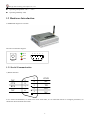
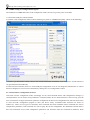
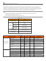
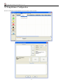
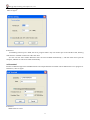
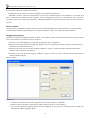
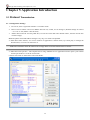
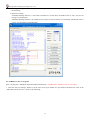
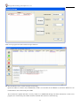
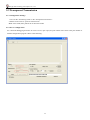
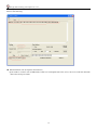
A-GPRS1090 User’s Manual Beijing ART Technology Development Co., Ltd. Beijing ART Technology Development Co., Ltd. Contents Contents ............................................................................................................................................................................2 Chapter 1 Introduction ..........................................................................................................................................................3 1.1 Overview.....................................................................................................................................................................3 1.2 Features .......................................................................................................................................................................3 1.3 Hardware Introduction ................................................................................................................................................4 1.3.1 Serial Communication..........................................................................................................................................4 1.3.2 Indicator Light......................................................................................................................................................5 1.4 Check List ...................................................................................................................................................................5 1.5 Installation Guide........................................................................................................................................................6 Chapter 2 Parameter Configuration ......................................................................................................................................7 2.1 Local Serial Port Configuration ..................................................................................................................................7 2.1.1 GPRS-Config.exe Configuration Program.......................................................................................................8 2.1.2 AT Parameter Configuration Protocol ..............................................................................................................8 2.2 Long-distance Configuration ....................................................................................................................................11 2.3 Message Configuration .............................................................................................................................................12 Chapter 3 Function Settings Description ............................................................................................................................13 Chapter 4 Server program ...................................................................................................................................................16 4.1 Overview...................................................................................................................................................................16 4.2 Usage Instructions.....................................................................................................................................................16 Chapter 5 Application Introduction ....................................................................................................................................20 5.1 Protocol Transmission...............................................................................................................................................20 5.1.1 Configuration Settings ...................................................................................................................................20 5.1.2 ARTServer Server Program............................................................................................................................21 5.2 Transparent Transmission .........................................................................................................................................29 5.2.1 Configuration Settings ...................................................................................................................................29 5.2.2 Server Configuration......................................................................................................................................29 Chapter 6 Fault Diagnosis...................................................................................................................................................31 2 Beijing ART Technology Development Co., Ltd. Chapter 1 Introduction 1.1 Overview GPRS is short for General Packet Radio Service, it has superiority owe to its high-speed transmit and always online, and it is very fit for the situation that there are much data to transmit but the time is not continuous. GPRS1090 data acquisition is an extension of PC-based data acquisition to measurement applications where cables are inconvenient or uneconomical.GPRS1090 data acquisition (DAQ) devices combine TCP/IP communication; the flexibility of driver software for remote monitoring, physical, mechanical, and acoustical signals. GPRS-1090 makes it easy to incorporate wireless into new or existing PC-based measurement or control systems. Operating System Support The operational under most popular operating systems such as windowsxp/2000/2003/Vista etc. however, ART device drivers provide easier installation, configuration and better performance for windowsXP, windows2000/2003, Vista, Please refer to the respective operating system's manual for how to install and configure the standard driver. Wide Applications A-GPRS1090 module has a wide range of applications, following are some typical applications: 1 Power Down Automatically Meter System 2 Environment Monitoring System 3 Urban Street Lamps Lighting System 4 Industrial Automation Control System 1.2 Features Support Dual-band GSM/GPRS; Transparent Data transmission: build-in TCP/IP protocol stack, provide RS-232/485 interface, provide transparent transmission channel Support data center dynamic domain name or IP address access Support three working mode: on-line forever, idle offline, and idle power-off Support the function that can be woken up by text message and mobile telephone Support the automatic re-connection function Support local and remote graphical interface for configuration and the maintenance Reliable design of multiple hardware and software, and build-in the watchdog Support dial-up Networking through the serial port Supply single voltage from +7V ~ +26V (Recommended +9V ~ +12V) Maximum operating current 300mA, and the sleep time≤10mA 3 Beijing ART Technology Development Co., Ltd. Operating Temperature: -20℃ ~ +70℃ Operating Humidity: 90% 1.3 Hardware Introduction A-GPRS1090 diagram is as follow: The side of schematic diagram: ACT 5 4 3 2 1 NET PWR PWR 9 8 7 6 1.3.1 Serial Communication 1) RS232 Interface NC 9 CTS 8 RTS 7 NC 6 5 GND 4 NC 3 TX 2 RX 1 NC If it is used with DAM3210, we need to use cross serial cable; if it is connected with PC to configure parameters, we should use direct-attached serial cable. 4 Beijing ART Technology Development Co., Ltd. 2) RS485 If RS485 uses 9D interface, shown as the following: NC 9 NC 8 NC 7 NC 6 5 GND 4 NC 3 DATA+ 2 DATA- 1 NC Otherwise, we also can lead out RS485 interface through 3P terminal, the side of schematic diagram: ACT NET 3 2 1 PWR PWR The definition of 3P terminal 3 2 1 1:GND 2:D3:D+ 1.3.2 Indicator Light NET: Network status indicator, on for normal PWR: Power indicator, on for normal ACT: GPRS status and communication indicator 1.4 Check List Unpack the A-GPRS1090 series package, you should find the following items: 1 A-GPRS1090 data acquisition module 2 Device driver diskettes: a) Driver; b) User's manual (this manual). 3 One serial port cable. 5 Beijing ART Technology Development Co., Ltd. 4 One 9V Power Supply. 1.5 Installation Guide Methods about how to install A-GPRS1090 in different operating systems are the same, our company provides a CD-ROM that contains the installation program “Setup.exe’’, and users double-click the installation program, then through the prompting of the interface to complete the installation. 6 Beijing ART Technology Development Co., Ltd. Chapter 2 Parameter Configuration We have three ways to configure parameters of A-GPRS1090: these are local COM port configuration, long-distance configuration and message configuration. 2.1 Local Serial Port Configuration There two configuration methods: GPRS-Config.exe configuration program or AT command. There are two ways can enter to the local configuration mode, show as follows. 1 When DTU power-on: when give the power to DTU, it will check whether there is space in the serial port, if there is space, that the user requested access to the configuration mode. Therefore, we only need to send space to serial port continuously before give the power to DTU (baud rate 115200, 8-bit data bit, 1 stop bit, noparity), and then give the power to DTU, you can enter the local serial port configuration mode. Note: If it receives character “e” when give the power to DTU, it will rest DTU; if it receives character “a”, we can do AT mandate for SIM300. 2 When DTU normal working: when DTU is in a normal communication status, we can send characters in table 2.1 to DTU through serial port to make DTU exit present work mode, and then enter the configuration mode. Table2.1 Pre-idle time Character Idle interval time Least 100ms +++ is set \r\n Least 100ms 7 Beijing ART Technology Development Co., Ltd. 2.1.1 GPRS-Config.exe Configuration Program The methord of A-GPRS1090 enters to the configuration mode: (first do not give the power to module) 1 Connect the COM port with the module. 2 Click the “enter configuration status” button, and then give power to A-GPRS1090 quickly. (Show as the following) 3 Click the “get information” button, then we can read the information of module, or we can wait for seconds because it can get information automatically. 4 In the left of user interface, there is a “local COM port configuration” tool, we can change the information in it, when it has been changed, we can save new information by clicking the “save configuration” button. 2.1.2 AT Parameter Configuration Protocol After DTU into the configuration mode, accordingly we can send command frames with configuration message, by command frames we can read or write parameters. Command frames all use ASCII characters. This not only gives the user convenient to use hyper terminal for parameter configuration in absence of configuration tool, but also allows users to write the DTU configuration program in their own device easily. Command frame structures are shown in Table2.1.4-1. There are two types of command, write commands and read commands. Write commands are used to configuration parameters, read commands are used to query the current configuration. The difference between them is that read commands are not with configuration parameters and characters after the command are different. Write 8 Beijing ART Technology Development Co., Ltd. commands "=" said the assignment. Read command "?" said the question. Command codes are different because the configuration objects are different, but these codes must comply with requirements of regulations (show as Table 2.1.4-2). If use other command codes, DTU will return “ERR CMD”, for another way, if write command with parameter configuration is not illegality (for example the baud rate has surpassed the scope of requirement), then DTU will refuse to receive this parameter and return “ERR DATA”. Note: 1 The data in command frame is all ASCII characters; all input characters are not case-sensitive 2 Command codes, according to Table 2.1.4-2 3 Write command frame length, according to Table 2.1.4-2. Table2.1.4-1 Command Frame Type Format Write Command AT+ command code=parameter Write Response Right OK\r\n Command mistake ERR CMD\r\n Parameter mistake ERR DATA\r\n Read Command AT+ Command Code?\r\n Read Response Command Code =Parameter\r\n Table2.1.4-2 Function name type Module type R DTUTYPE 10 Such as ART1090 Device ID R DTUID 15 unique ID, can not be changed Device software version R SWVER 5 Such as V1.00 Local COM Configuration length Settings Device name RW DTUNAM 15 Such as ARTDTU01 SIM card number RW PHON 11 Such as 15810437433 MODE 1 DTUMODE 1 Work mode Mode type Goal Setting code RW RW 0:onlineforever1:idle winding2:idlepower-down 0:client1:server 2:CSD client 3:CSD server Transport Mode RW DATMODE 1 Data Center number RW SVRCNT 1 1~2 DNS1 RW DNS1IP 15 Such as 202.106.0.20 DNS2 RW DNS2IP 15 Such as 211.136.17.107 Main Data Center IP RW SVRIP 15 Such as221.218.157.55 Main Data Center Domain RW SVRNAM 40 Such as “www.sohu.com” Main Data Center Port No. RW SVRPORT 5 Such as 80 9 Beijing ART Technology Development Co., Ltd. Transmission Control Network Parameters Control Command 0: TCP connection Main Data Center Link Mode RW SVRMODE 1 Backup Data Center IP RW SVR1IP 15 Such as 192.168.0.1 Backup Data Center Domain RW SVR1NAM 40 Such as “www.163.com” Backup Data Center Port No. RW SVR1PORT 5 Such as 80 Backup Mode RW SVR1MODE 1 The number of reconnection RW TRYCNT 2 1~99 The number of reconnection interval RW TRYTIM 5 10~65534s Two batches of target reconnection interrupt interval RW TRYSPAC 5 COM Baud Rate RW SERBAUD 6 300~115200 COM Data Bit length RW SERDAT 1 5~8 COM Stop Bit length RW SERSTP 1 1~2 Serial Check Type RW SERCHK 4 Heartbeat Packet Interval RW BEATTIM 5 30~65534s Heartbeat Packet Timeout RW BEATOUT 5 30~65534s Heartbeat packet data setting RW BEATDATA 2 One byte of Hex, such as: FE Frame interval RW SERS 5 Packet Maximum Length RW MTU 4 1~1024 byte Idle offline time RW IDLETIM 5 30~65534ms APN RW APN 20 Default empty APN User Name RW USRNAM 20 Default empty APN Password RW PWD 20 Default empty SMS Center No. RW SMSNO 14 Default empty Local Port No. RW LCOPORT 1 Default “2020” SMS Certification User 1 RW USERNO1 14 SMS Certification User 2 RW USERNO2 14 SMS Certification User 3 RW USERNO3 14 Module Password RW DTUPWD 6 ON: putout Debugging information output RW 3 ON: putout Data Center Link 10 DBGINF 1: UDP connection 0: TCP connection 1: UDP connection Beijing ART Technology Development Co., Ltd. 2.2 Long-distance Configuration Remote configuration using ARTServer service program, show as figure: 11 Beijing ART Technology Development Co., Ltd. 2.3 Message Configuration SMS configuration is a mobile phone, enter commands to configure, but please note: Note: One message only can send one command, format is: 6 passwords +":"+ command (without the prefix "AT +"). All characters are Western. Not only the telephone number is the same as certification number, but also the passwords have been passed, then SMS configuration can work. SMS wake-up command "WAKEUP". SMS Configuration Support Telephone wake-up: telephone call’s time must over two rings, and was hung up after the wake-up. 12 Beijing ART Technology Development Co., Ltd. Chapter 3 Function Settings Description Export Configuration Save the modified configuration items. Import Configuration Load the configuration items previously saved. Reset DTU Module Software reset actions will be executed. Restore Factory Settings Restore module to factory settings in case of configuration confusion. SWVER Software version. DTUNAM DTU device name, be used to distinguished different devices when multiple modules are being used. DTUNAM limited to 15 characters. SIM Card Number (PHON) Mobile phone number, 11 ASCII characters, such as "15810437433". MODE There are three modes for A-GPRS1090:“Always online”, “Offline when idle”, “Power down when idle”. Always online: It will connect to the preconfigured server when power on the module. And it will be kept online all the time so the data can be transmitted at any time. Offline when idle: It will connect to the preconfigured server when power on the module. The module will disconnect and turns to the sleeping mode if there isn’t any data in a period of time. There are three methods to enable re-establish connection between the module and the server. 1. Send data to the serial port of the module, the module will connect to the server and then send the out. . 2. Telephone wake-up: call the SIM card number, hang up after it rings for two times, the module will re-establish a connection with the server 3. SMS wake-up: set one of the SMS certification users to the SIM card number in the Configuration Tool. The format of the number is “+861**********”. (for China’s SIM card, it is 86) Send the SMS “888888: Wakeup”. It will return “OK” which means the module has re-connected to the serve. Power down when idle: after the module disconnecting the connection with the server, the module will cut off the power of GPRS module, and make the system into power-down status to achieve low power consumption There is only one method to wake up the module: send data to the serial port of the module, the module will connect to the server after the data is sent successfully. 13 Beijing ART Technology Development Co., Ltd. DTUMODE This parameter is used to set the module's functionality mode, "CLIENT" or "SERVER". For “CLIENT” mode, the module connects the data center server as a client. For “SERVER” mode, the module wait for the connection from the client as a server. When use the point to point function, configure one module “CLIENT”, and the other “SERVER”. SVRIP, SVRNAM, SVRPORT, CNTMODE (the parameters of the main center server) A target server configuration includes IP address and port number, if the server does not have a fixed IP address, you can use the domain name. When the server IP address is validity, the domain name will be ignored. In communication network, it has TCP and UDP communication. SVR1IP1, SVR1NAM1, SVR1PORT1, CNTMODE1 (the parameters of the secondary center server) A target server configuration includes IP address and port number, if the server does not have a fixed IP address, you can use the domain name. When the server's IP address validity, the domain name will be ignored. In the several attempts to connect the main central server fails, the module will automatically switch to connect alternate central server. When using the standby server, if it suddenly disconnected during the remote configuration, the module will re-connect standby server. If it suddenly disconnected in operating mode, the target server will switch back to the main central server. TRYCNT, TRYTIM, TRYSPAC The number of target re-connection, used to control the number of the same goal connection of the connection with batch. “0” stands for regardless of batch. The interval of target connection is used to control the time between two connections, the smallest time is 10s, and the longest time is 65.5536s. The interruption interval of target connection is used to control the time of two groups’ connections, the smallest is 1 minute, and the longest is 65,534 minutes. SERBAUD Serial baud-rates. Table3.13 Supported baud-rates Standard baud-rate 300 600 1200 2400 4800 9600 19200 38400 57600 115200 SERDAT, SERSTP Serial data bit (stop bit) length. SERCHK Check type of serial. Table3.15 relationship between values and checking types Baud-rate Set value No checking Odd checking Even checking NON ODD EVEN Compulsory to 1 1 BEATTIM Users can set heartbeat packet interval time, the range is 30 ~ 65534 (unit: seconds). 14 Compulsory to 0 0 Beijing ART Technology Development Co., Ltd. BEATDATA User can manually set the heartbeat data, such as: "0x3F", using the AT command configuration, format: "AT + BEATDAT = 3F". SERS,MTU Frame interval of time and the maximum length of data packets IDLETIM Idle time of downline. APN,USRNAM,PWD APN name, user name, and password. LCOPORT Local port number. DTUPWD Login Password. DBGINF This parameter controls whether the data input is "echo" and whether there are "debug information" outputs. 15 Beijing ART Technology Development Co., Ltd. Chapter 4 Server program 4.1 Overview ARTServer is a wireless communication server application which is running on Windows operating systems. A-GPRS1090 module is supplied by our company ,it can transmits communication between module and server, client connections, management, client mapping, data transmission and other functions can be realized by the server. 4.2 Usage Instructions Application framework Show as figure: 16 Beijing ART Technology Development Co., Ltd. Server Settings Show as figure: Instruction: 1) Defaulting monitor port is 8000; the server program allows only one monitor port to the outside world, allowing 1000 clients to establish connection at the same time. 2) Users can also select "When Windows starts activated A-GPRS automatically ", and then when users open the computer, ARTServer will be activated automatically. Add terminal Wireless module through name and IMEI which is the unique identifier of module can be added in the server program of ARTServer, show as figure: Instruction: 1 IMEI must be 15 bits. 17 Beijing ART Technology Development Co., Ltd. 2 "Terminal existence”: If you do not choose the "Terminal existence", it will be an invalid terminal, ARTServer does not accept the connection request from terminal. 3 "Heartbeat interval" refers to the time of sending a terminal heart to ARTServer. "Heartbeat overtime" means the terminal does not receive the heartbeat packets from ARTSever for seconds, and then it will think the module has been dropped. After has dropped the terminal it will determine next connection according to their own "try spacing" parameter. Heartbeat parameters ensure the terminal on line; the value can be set by users. Delete terminal Click the list box to delete the terminal, select the menu "Terminal Management | delete Terminal" or click the toolbar "terminal delete" button, pop-up dialog box to confirm the deletion. Clicks “Yes” while the terminal deleted. Mapping management ARTServer supports four mapping methods: terminal –to- terminal, terminal -to-local physical serial port, terminal to the local virtual serial port, terminal to the local TCP port. 1 terminal –to- terminal mapping: two terminals exchange the data by ARTServer. 2 Terminal to the local physical serial mapping: ARTServer opens a specified and actual serial port, and then transmit data between terminal and the serial. 3 Terminal to the local virtual serial port mapping: ARTServer creates a virtual serial port, and then transmit data between virtual serial port and terminal. 4 Terminal to the local TCP port mapping: ARTServer opens a local server port, and then transmit data between terminal and the TCP port. Show as figure: Instruction: 1 terminal own should not map, when map TCP ports, TCP port numbers are different. 2 Make sure that no program is opening the virtual serial port when we want to delete it. 3 If you want to delete the mapping, please click the "Mapping" to remove the one which you want to delete, and then click the "delete mapping" option. 18 Beijing ART Technology Development Co., Ltd. Information ARTServer has “system information” and “terminal information”. 1. “System information” shows the total number of terminals and the number of online terminals. 2. “Terminal information” shows terminal connection status, heart rate, receive and send data. 19 Beijing ART Technology Development Co., Ltd. Chapter 5 Application Introduction 5.1 Protocol Transmission 5.1.1 Configuration Settings 1. First of all, select "Agreement transfer" of "transfer mode". 2. DNS of "Server DNS1" and "server DNS2" has been set, if need, we can change it. (Default settings are: DNS1 = 211.136.17.107, DNS2 = 202.106.0.20). 3. "Master data center IP" uses the public IP (if we use the "main data center domain name", then the current item must be empty). Note: the public network IP address changes every day, so it needs to be updated. 4. "Main data center domain," we can use software to application a domain name, by a third party to manage the domain name, it is more convenient for us. Note: The "main data center IP" must be set to empty when we use the domain name to connect. 5. "Main data center port No.": The computer that is using "ARTServer.exe" application needs to open a port number and the port number is set in the current item. 6. Select TCP mode of "Main Data Center link Mode". 20 Beijing ART Technology Development Co., Ltd. 7. Serial port settings: A-GPRS1090 provides a serial port to transfer the data; serial port configuration is shown as the following. 8. Heart rate settings: "Heartbeat Package Interval": it will send a heartbeat in a certain time, the default value is "30s", and we can change it in the program. "Heartbeat Package Timeout": the module will re-connect in timeout if there is no heartbeat. The default value is "120s"; we can change it in the program. 5.1.2 ARTServer Server Program Start \ all programs \ ART Data Acquisition Measurement Suite \ A-GPRS1090 \ ARTServer Service procedure 1. Click the "Service Settings" button to set the main server port number (the port number should be the same as the "Main Data Center Port No."), show as the following: 21 Beijing ART Technology Development Co., Ltd. 2. Click the "Start Service" button to create a master server. Show as the following: 22 Beijing ART Technology Development Co., Ltd. 3. Power on A-GPRS1090 module, (insert the SIM card which has GPRS services to the module).Then waiting for the module to connect the server. After seconds, the module connects the server successfully, show as the following: 4 The server program realizes data transmission, and it can achieve physical serial port forwarding, TCP port forwarding, and virtual serial port forwarding. (1) "Physical serial port forwarding" test Click the left "Mapping management" button, it will pop-up dialog box. 23 Beijing ART Technology Development Co., Ltd. Map the DTU1090-0 which is new connection device to the physical serial port, serial number is COM1. Click the serial configuration dialog box, show as the following: configure serial. (The "mapping" button is valid after configured the serial port) Click the “Mapping” button, show as the following: 24 Beijing ART Technology Development Co., Ltd. Then master service will add the physical serial port forwarding function: ★ Data distribution rules (physical serial port forwarding) Open the serial port COM3 to connect A-GPRS1090 device, connect the physical serial port COM1 with another unoccupied serial port COM2, COM3 can send data to ARTServer, and then data is transmitted from the server to the COM1. We can detect the uplink data that is sent by COM3 of A-GPRS1090 through "terminal information" of the server program; COM1 can connect with other devices to send the downlink data. (2) "TCP serial port forwarding" test Click the left "Mapping management" button, it will pop-up dialog box. 25 Beijing ART Technology Development Co., Ltd. Map the DTU1090-0 which is new connection device to the TCP serial port, we can change serial number, the default number is 5000. Click the “mapping "button, show as the following: Then master service will add the TCP serial port forwarding function: ★ Data distribution rules (TCP serial port forwarding) Open the COM1 to connect with the serial port of A-GPRS1090, then COM1 can send the data to the ARTServer, then ARTServer can transmit data to the serial port 5000 of TCP. Open “Network Debugging Assistant”, we can use it as client to connect with serial port 5000 of TCP, in this way, it can realize data transmission. Show as the following: 26 Beijing ART Technology Development Co., Ltd. We can detect the uplink data that is sent by COM3 of A-GPRS1090 through "terminal information" of the server program; the serial port 5000 of TCP sends the downlink data. Shown as the following: (3) "Virtual serial port forwarding" test Click the left "Mapping management" button, then it will pop-up dialog box. Map the DTU1090-0 which is new connection device to the virtual serial port, serial port is COM6. Click the “mapping "button, show as the following: 27 Beijing ART Technology Development Co., Ltd. Main server program will add virtual serial port function: ★ Data distribution rules (virtual serial port forwarding) Open the COM1 to connect with A-GPRS1090, COM1 can send data to the ARTServer, and then ARTServer can transmit data to the virtual serial port COM6. We can detect the uplink data that is sent by COM1 of A-GPRS1090 through "terminal information" of the server program, the virtual serial port COM6 sends the downlink data. Shown as the following: 28 Beijing ART Technology Development Co., Ltd. 5.2 Transparent Transmission 5.2.1 Configuration Settings 1 First set the "transferring mode" to the "transparent transmission." 2 Others are the same as “protocol transmission”. Note: in this mode, data packets do not have the header. 5.2.2 Server Configuration Use “Network Debugging Assistant “to create a server, open a port, the port number is the same as the port number of module configuration program. Show as the following: 29 Beijing ART Technology Development Co., Ltd. Give the power to A-GPRS1090, waiting until the module connects with the server. Show as the following: ★ Data distribution rule (transparent transmission) Open COM1 to connect with A-GPRS1090, COM1 can send uplink data to the server; the server sends the downlink data to the serial port COM1. 30 Beijing ART Technology Development Co., Ltd. Chapter 6 Fault Diagnosis The following are a series of common faults of GPRS1090, possible causes and solutions. If the problem persists, users can directly connect with the ART in order to get technical support. 1 The module can not work well; possible reasons are in the following: a) The antenna does not contact well; b) The SIM card does not contact well; c) The SIM card does not have the money; d) The network is not connection or the speed is too slowly. e) Public Network IP has changed or oray has disconnected. 2 when working a period of time, the module short-terms automatically, the possible reasons are in the following: a) The Network is not connecting well; b) If using Public Network, it maybe the Public Network has changed; c) The SIM card does not have the money; d) The module receives too many data in one time. 31