1
Operating Instructions
AirChek® XR5000
SKC Inc.
863 Valley View Road
Eighty Four, PA 15330 USA
Form #38047 Rev 1010
Table of Contents
Description .......................................................................................................................1
Performance Profile ........................................................................................................2
Setup.................................................................................................................................4
Charging the Battery Pack (Li-Ion) ...........................................................................4
Reading the Charging Status LED on the Single Charger............................5
Keypad Basics .........................................................................................................6
Turning the Pump On ...............................................................................................6
Turning the Pump Off ...............................................................................................6
Locking the Keypad .................................................................................................7
Checking Battery Charge Level ...............................................................................7
Accessing User Setup Functions .............................................................................7
Entering Functions ........................................................................................7
Exiting Functions ...........................................................................................7
User Setup Functions ..............................................................................................8
Function Overview ........................................................................................8
Clearing Accumulated Run Time...................................................................8
Setting Flow Rate ..........................................................................................8
Setting a Timed Run......................................................................................9
Setting a Run Delay with Continuous Run ....................................................9
Setting a Run Delay and Timed Run ...........................................................10
Canceling a Timed Run and/or Run Delay .................................................. 11
Calibration ......................................................................................................................12
High Flow: 1000 to 5000 ml/min ............................................................................12
Low Flow: 5 to 500 ml/min .....................................................................................13
Sampling ........................................................................................................................14
Sampling ................................................................................................................14
Flow Fault ..............................................................................................................14
Battery Replacement .....................................................................................................16
Replacing the Battery Pack (Li-Ion) .......................................................................16
Changing the Batteries (Alkaline) ..........................................................................17
Maintenance ...................................................................................................................19
Accessories ...................................................................................................................20
Replacement Parts ........................................................................................................21
Warranty .........................................................................................................................21
Indicates a warning or caution.
www.skcinc.com
AirChek XR5000 Quick Guide
Keypad Basics
Ò (star key)
ST (up/down arrow keys)
Scrolls through parameters in user setup functions.
Increase or decrease flow rate, timed run, and run delay time.
Key Sequences
TÒ
[ST]
Press keys individually.
Press keys simultaneously. Toggles between Run and Hold
and exits user setup functions.
Security code to access user setup functions. With pump in a
non-running state (no flashing blue LED), press keys in
sequence.
ÒSTÒ
Operation
Press and hold Ò.
Press and hold Ò through countdown. Auto-off will shut down
pump after 5 minutes without activity.
Press [ST] to toggle between Run and Hold.
Press T 5 times quickly to activate. Press T 5 times quickly
to deactivate.
With pump in a non-running state (no flashing blue LED),
press [ST] to run pump. Press [ST] to Hold pump when
completed.
• Pump On
• Pump Off
• Mode Change
• Keypad Lock
• Run/Hold
Accessing User Setup Functions
• Entering User Setup Functions
With pump in a non-running state (no flashing blue LED), press ÒSTÒ.
• Exiting User Setup Functions
Press [ST]. Pump is ready. Press [ST] to run the pump or to start a run delay.
User Setup Functions
To navigate while in user setup functions, press Ò until the desired function displays.
Function
When LCD Displays
User Action
Result
Clear Accumulated
Run Time
CLr and flashing
Hold
Press [ST].
Clears run and run
time and exits functions. Press [ST] to
run pump.
Adjust Flow Rate*
“---” and flashing
ADJ Flow
Press S or T.
Press [ST] to exit
functions.
Flow increases/
decreases. Press
[ST] to run pump.
Set Timed Run†
Flashing Set Timed
Run and min
Press S or T.
Press [ST] to exit
functions.
Minutes increase/
decrease. Press
[ST] to run pump.
Set Run Delay†
Flashing Set Run
Delay and min
Press S or T.
Press [ST] to exit
functions.
Minutes increase/
decrease. Press
[ST] to start run
delay. Blue LED
flashes. Pump starts
after delay elapses.
Function only available
when accumulated run
time exists.
* Changing flow rate in user setup functions will not clear accumulated run time.
† Changing timed run and/or run delay settings in user setup functions will clear accumulated run time.
www.skcinc.com
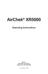
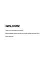
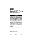
Description
SKC AirChek XR5000 Sample Pumps are designed to offer users enhanced battery
power and easy operation in a lightweight pump that provides accurate airflows from
5 to 5000 ml/min.
• Three battery options provide flexibility and economy for different applications
including long run times.
• The large three-button keypad and straightforward user setup functions offer userfriendly conveniences.
AirChek XR5000 pumps feature a patented* isothermal flow sensor that measures flow
directly and acts as a secondary standard, constantly maintaining the set flow rate. A
built-in sensor compensates for changes in temperature that occur after calibration.
* U.S. Patent No. 5,892,160
Inlet Port with
Protective Filter
Battery Charge
Level Indicator
Bright blue
pump status
LED
Easy-to-read
Liquid Crystal
Display (LCD)
Large,
simple
Operating
Keypad
Battery Pack
(3 options
available)
Not shown:
Beltclip (back)
Battery
Charging Jack
(back)
AirChek XR5000 Air Sampling Pump
1
Performance Profile
Flow Range:
1000 to 5000 ml/min (5 to 500 ml/min requires optional
low flow adapter kit)
Compensation Range:
5000 ml/min at 10 inches water back pressure
4000 ml/min at 20 inches water back pressure
2000 ml/min at 50 inches water back pressure
Typical Back Pressure of Sampling Media (inches water)
Flow Rate (L/min)
1.0
1.5
2.0
2.5
3.0
3.5
Filter/Pore Size (μm)
25-mm MCE/0.8
6
9
12
15
18
21
25-mm MCE/0.45
14
22
28
35
40
44
37-mm MCE/0.8
2
3
4
5
6
7
37-mm PVC/5.0
1
1
2
2
2.5
3
37-mm, polycarbonate/0.45
4
6
8
10
12
15
25-mm MCE/0.45 microvacuum
21
31
40
48
59
69
37-mm PTFE/1.0
7.5
11
14.5
19
22
26
Compare the information in this table to pump compensation range to determine appropriate applications.
Flow Compensation
System:
Accuracies:
5.0
25
50
9
3
17
79
30
31
63
11
4
21
100
40
Patented* isothermal closed loop flow sensor
Timing:
Flow Rate:
Battery Charge
Level Indicator:
4.0
1 min/mo at 25 C
± 5% of set-point after calibration to
desired flow
Icon displays on LCD at full, mid, low charge, imminent
low battery fault, and low battery fault.
Temperature Range:
Operating:
Charging:
Storage:
32 to 113 F (0 to 45 C)
32 to 113 F (0 to 45 C)
-4 to 95 F (-20 to 35 C)
Operating Humidity:
0 to 95% non-condensing
†
Typical Run Time :
XR5000 Model
2 L/min
5 L/min
High-power Li-Ion
40 hrs
22 hrs
Standard Li-Ion
20 hrs
11 hrs
Alkaline
18 hrs
8 hrs
† Using a 37-mm 0.8-μm MCE filter
For extended run times, the pump may be operated while
attached to the charger.
Timed Run, Run Delay,
and Continuous Run
Display Range:
Flow Fault:
1 to 9999 minutes (6.8 days). If run time exceeds
6.8 days, timer display rolls over.
If pump is unable to compensate for > 15 seconds due to
excessive back pressure, the pump stops, displays flow
fault icon, and holds run time display. Auto-restart is
attempted every 15 seconds up to 5 times.
* U.S. Patent No. 5,892,160
2
Performance Profile
Low Battery Fault:
15 seconds to sleep
Auto-off:
5 minutes of inactivity
Battery Pack:
High-power Li-Ion (4 cell), rechargeable, 7.4 V, 4.4-Ah
capacity, 32.6 Wh (Cat. No. P85004 for UL Listed pump)
or
Standard Li-Ion (2 cell), rechargeable, 7.4 V, 2.2-Ah
capacity, 16.3 Wh (Cat. No. P85002 for UL Listed pump)
or
Alkaline (6 cell), disposable, size AA, 1.5 V (nominal),
Cat. No. P75715 - not UL Listed for intrinsic safety
(model dependent)
Battery Recharge Time:
(with SKC-approved chargers;
varies with battery capacity
and level of discharge)
Standard Li-Ion (2 cell): approximately 4 hrs
High-power Li-Ion (4 cell): approximately 8 hrs
Size:
High-power Li-Ion
and alkaline models: 5.5 x 3 x 2.3 in (14 x 7.6 x 5.8 cm)
Standard Li-Ion model: 4.3 x 3 x 2.3 in (10.9 x 7.6 x 5.8 cm)
Weight:
High-power Li-Ion:
21 oz (0.6 kg)
Standard Li-Ion model: 16 oz (0.45 kg)
Alkaline model:
17 oz (0.48 kg)
Case:
Anti-static plastic
RFI/EMI Shielding:
CE marked for RFI/EMI protection
Approvals:
•
for use in hazardous locations. Models that are
UL Listed for intrinsic safety contain the
logo on
the label. These models must be used with battery pack
Cat. No. P85004 or P85002 to maintain the UL intrinsic
safety listing.
• RoHS compliant
Cautions:
• For safe operation in hazardous locations, ensure the pump label
contains the
logo and the battery pack label contains Cat.
No. P85004 or P85002. Use of any other battery pack (including
alkaline) or device to power the pump voids the UL Listing for
intrinsic safety.
•
Use only the charger and battery packs designed for the AirChek
XR5000 pump to ensure reliable performance. Failure to do so voids
any warranty.
•
Remove alkaline batteries from pump before storage to prevent damage from battery leakage.
•
Use only SKC-approved parts to ensure reliable performance and to
maintain the UL Listing for intrinsic safety. Failure to do so voids any
warranty.
•
Failure to follow warnings and cautions voids any warranty.
3
Setup
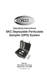
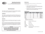
Charging the Lithium-Ion Battery Pack
For models containing a lithium-ion battery pack only.
Shown with single charger (Cat. No. 222-241). A
five-station charger is available; see Accessories
on page 21. Follow charger instructions.
STOP!
Completely charge a new battery pack
before operating the pump. It may be
necessary to charge the battery a few
times before maximum battery capacity
is achieved.
Intrinsic safety circuitry inside the
battery causes the pump to selfdischarge during storage. Charge
Li-Ion pump battery completely
before calibration and sampling to
achieve optimum pump operation.
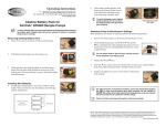
1.
Power
supply
Jack
Charging
unit
Battery
charging
jack
AirChek XR5000 charging train
with single charger
For a complete charge, ensure the pump is not running. Insert plug on charging
unit into the battery charging jack on back of pump. Ensure plug is oriented so
that the arrow on the plug is facing upward.
Ensure proper orientation of charging cable before plugging it into
the charging jack. Improper orientation/contact will short circuit the
battery and voids any warranty.
Short circuiting the battery pack will render it immediately inoperative.
2.
Insert plug on power supply into jack on charging unit.
3.
Pull locking tab to side and insert appropriate
wall plug into power supply. Release locking
tab. Plug power supply into a wall outlet.
The standard 2-cell Li-Ion battery pack will
recharge in approximately 4 hours. The highpower 4-cell Li-Ion battery pack will recharge in
approximately 8 hours. Run pump for 5 minutes
after charging is complete.
Interchangeable wall plugs
insert into power supply.
Note
After charging the battery pack, it is good practice to run the pump for
approximately 5 minutes before calibrating. This ensures the battery is
in more steady-state conditions and improves the agreement in pre and
post-sampling calibrations.
4
Setup
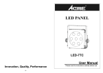
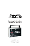
Reading the Charging Status LED on the Single Charger
The Li-Ion Charging Unit (Cat. No. P22300) indicates battery charge status via
an LED on the unit that blinks in specific patterns. Observe the LED steadily for
> 5 seconds to read charge status.
Power supply
jack
LED Action
Charge Status
ON
Ò
steady
Charge in progress
ON
Ò
2 sec
OFF
{
.25 sec
ON
Ò
2 sec
(Repeats)
Approximately
80% charged
OFF
{
2 sec
ON
Ò
.25 sec
OFF
{
2 sec
(Repeats)
Charge completed
Note
Charge status
LED
The battery pack may be kept on SKC-approved Li-Ion battery chargers for
an indefinite time.
Cautions:
• Do not charge or operate pump from charger in hazardous
locations.
•
Use only the charger and battery packs designed for the AirChek
XR5000 pump to ensure reliable performance. Failure to do so will
void any warranty.
•
For safe operation in hazardous locations, ensure the pump label
contains the
logo and the battery pack label contains Cat.
No. P85004 or P85002. Use of any other battery pack (including
alkaline) or device to power the pump voids the UL Listing for
intrinsic safety.
•
Tampering with the battery pack or using a repaired or rebuilt
battery pack voids any warranty and UL Listing for intrinsic safety.
•
Do not open, disassemble, short circuit, crush, incinerate, or
expose the battery to fire or high temperatures.
•
Remove alkaline batteries from pump before storage to prevent damage from battery leakage.
•
Use only the SKC-approved charger for this pump. Use of an
unapproved charger may damage the battery and pump and voids
any warranty.
•
Failure to follow warnings and cautions voids any warranty.
See http://www.skcinc.com/instructions/1756.pdf for more information
on SKC pump battery packs.
5
Setup
Keypad Basics
The AirChek XR5000 operates by pressing key sequences
on the keypad located on the front of the pump case.
Keys
Ò
Scrolls through parameters in user setup functions
S
Increases flow rate, timed run, and run delay time
T
Decreases flow rate, timed run, and run delay time
Key Sequences
Up
arrow
key
Star
key
Down
arrow
key
SÒ
Press keys individually.
[ST]
Press simultaneously to toggle between Hold and Run modes and to exit user
setup functions.
ÒSTÒ Security code. With pump in a non-running state (no flashing blue LED), press
to access user setup functions.
Turning the Pump On
• Press and hold Ò until display shows “ON”.
• Press [ST] to run the pump or to place a running
pump in Hold. A blue LED on top of the pump
indicates pump is running or that there is a run
delay programmed into the pump.
Turning the Pump Off
• Manual Off (Sleep mode): With pump in a nonrunning state (no flashing blue LED), press and
hold Ò until a countdown from 3 to 1 appears
on the LCD and pump shuts off. Manual Off will
operate even when keypad is locked.
• Auto Off (Sleep mode): Turns off a non-running
pump (no flashing blue LED) after five minutes of
inactivity.
6
Setup
Locking the Keypad
Locking: In any mode, press T 5 times quickly.
A flashing “L” will appear in the lower right corner
of the display.
Unlocking: Press T 5 times quickly. The flashing
“L” will disappear from the display. The keypad
may be operated normally.
Note
• While the keypad is locked, the Ò key will still operate to allow manual
pump shut off in a non-running state (no flashing blue LED).
• A locked keypad will remain locked until the user unlocks it. Turning the
pump off and on does not affect keypad lock status.
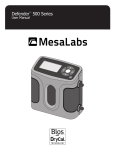
Checking Battery Charge Level
Three bars indicate a full charge (normally appears after charging), approximately
75% to 100%.
Two bars indicate the battery is charged enough to operate the pump, approximately 25% to 75%.
One bar indicates battery charge is low (charge battery), approximately 1% to 25%.
No bars indicate that low battery fault is imminent.
Low Battery Fault
No bars and a flashing outline indicate a low battery fault (pump will go into
Hold and go to sleep after 15 seconds in low battery fault). Accumulated run time
will be retained.
Accessing User Setup Functions
Entering Functions:
• With pump in a non-running state (no flashing blue LED), press ÒSTÒ.
Exiting Functions:
• Press [ST] to exit user setup functions. Pump is ready to run.
Note
User setup functions cannot be accessed while the keypad is locked.
7
Setup
User Setup Functions
Function Overview
User setup functions are listed below in the order in which they display. Note that the
CLr function for clearing accumulated run time is only available when accumulated
run time exists.
No Accumulated Run Time
ADJ Flow
Set Timed Run
Set Run Delay
Accumulated Run Time
CLr
ADJ Flow
Set Timed Run
Set Run Delay
Clearing Accumulated Run Time
1.
2.
With the pump in a non-running state (no flashing blue
LED), press ÒSTÒ.
Press [ST] at CLr display to clear accumulated run
time. Pump is ready to run.
Note
CLr will not cancel Timed Run or Run Delay time settings (see Canceling a
Timed Run and/or Run Delay).
Note
• Changing the timed run and/or run delay settings in user setup functions will
automatically clear accumulated run time.
• Changing the flow rate in user setup functions will not clear accumulated
run time.
Setting Flow Rate
1.
2.
3.
4.
5.
With pump in a non-running state (no flashing blue
LED), press ÒSTÒ.
Connect pump inlet to a calibrator.
Press Ò until ADJ and Flow flash on display.
Press S to increase or T to decrease flow. Dashed
lines will move up and down on the LCD to indicate
direction of adjustment. Flow rate will not display
on the pump LCD. Observe the calibrator for flow
reading.
Press [ST] to accept flow setting and to exit user setup functions.
See Calibration for instructions on calibrating pump flow rate.
8
Setup
Setting a Timed Run
Program the AirChek XR5000 from its keypad to run from 1 to 9999 minutes.
With pump in a non-running state (no flashing blue LED):
1. Press ÒSTÒ to enter user setup functions.
2. Press Ò until a flashing Set Timed Run and min
appear on the display.
3. Press S to increase or T to decrease minutes.
4. Press [ST] to accept timed run setting and to exit user setup functions. The
setting will appear on the display and the pump will be ready to run.
5. Press [ST] to run the pump.
During a timed run:
a. The blue LED on top of the pump case will flash.
“Timed Run Remaining” will display and count down in
minutes on the LCD.
b. Accumulated run time can be displayed by pressing and
holding S.
c. Run can be paused (Hold) by pressing [ST]. The time remaining and accumulated run time displays will freeze. Run can be resumed by pressing [ST]. Time
remaining and cumulative run time will resume.
d. At the end of the run, the pump will stop and “Timed Run Remaining” and “0”
will display. To display accumulated run time, press and hold S.
e. To return to “Timed Run” display, press [ST]. This will also clear accumulated
run time.
Note
Reminder
If pump goes to sleep following the run and is awakened, the pump will
display “Timed Run Remaining” and “0.” Accumulated run time from the run
remains and can be displayed by pressing and holding S.
Pressing [ST] after a completed run automatically clears accumulated run
time.
Setting a Run Delay with Continuous Run
Program the AirChek XR5000 from its keypad to automatically start a sample run after
a specified period of time (1 to 9999 minutes) has elapsed.
With pump in a non-running state (no flashing blue LED):
1. Press ÒSTÒ to enter user setup functions.
2. Press Ò until a flashing Set Run Delay and min appear
on the display.
3. Press S to increase or T to decrease minutes.
4. Press [ST] to accept run delay setting and to exit user setup functions. Run
delay time will display on the LCD and the pump will be ready to start run delay.
5. Press [ST] to activate the pump.
9
Setup
During a run delay with continuous run:
a. The blue LED on top of the pump case will flash during the run delay even though
the pump is not running.
b. Run delay time remaining will count down in minutes and
display on the LCD.
c. Once the run delay time has elapsed, the pump will start
running. Accumulated run time will count up in minutes.
d. Run can be paused (Hold) by pressing [ST]. The accumulated run time display
will freeze. Run can be resumed by pressing [ST]. Accumulated run time display will resume.
e. Once the run is complete, stop the pump by pressing [ST]. Accumulated run
time will display.
Note
If pump goes to sleep following the continuous run and is awakened, the
pump will display accumulated run time.
Setting a Run Delay and Timed Run
With pump in a non-running state (no flashing blue LED):
1. Press ÒSTÒ to enter user setup functions.
2. Press Ò until flashing Set Timed Run and min appear
on the display.
3. Press S to increase or T to decrease minutes (1 to
9999 minutes).
4. Press Ò to scroll to a flashing Set Run Delay and min.
5. Press S to increase or T to decrease minutes (1 to
9999 minutes).
6. Press [ST] to accept run delay and timed run settings
and to exit user setup functions. The run delay setting
will appear on the LCD and the pump will be ready to start run delay.
7. Press [ST] to activate the pump.
During a run delay with timed run:
a. The blue LED on top of the pump case will flash during the run delay even though the pump is not running.
b. Run delay time remaining will count down in minutes
and display on the LCD.
c. Once the run delay time has elapsed, the pump will
start running. “Timed Run Remaining” will display
and count down in minutes on the LCD.
d. Accumulated run time can be displayed by pressing
and holding S.
e. Run can be paused (Hold) by pressing [ST]. The time remaining and accumulated run time displays will freeze. Run can be resumed by pressing [ST]. Time
remaining and cumulative run time will resume
10
Setup
f.
g.
At the end of the run, the pump will stop and “Timed Run Remaining” and “0”
will display. To display accumulated run time, press and hold S.
To return to “Timed Run” display, press [ST]. This will also clear accumulated
run time.
Note
If pump goes to sleep following the timed run and is awakened, the pump
will display “Timed Run Remaining” and “0.” Accumulated run time from the
run remains and can be displayed by pressing and holding S.
Tip
When setting a timed run or run delay with a large number of minutes in user
setup functions, press Ò with S or T. This activates the speed count feature
which scrolls through timed run or run delay minutes in increments of 100.
Reminder
Pressing [ST] after a completed run automatically clears accumulated run
time.
Canceling a Timed Run and/or Run Delay
With pump in a non-running state (no flashing blue LED):
1. Press ÒSTÒ to enter user setup functions.
2. Press Ò until flashing Set Timed Run and min appear
on the display.
3. Press T until time displays as 0.
4. Repeat for Run Delay if needed.
5. Press [ST] to exit user setup functions. Pump will be ready to run.
Note
Selecting CLr in user setup functions after a sample run will clear accumulated
run time only. It will not clear Timed Run or Run Delay time settings.
11
Calibration
Calibration (High Flow: 1000 to 5000 ml/min)
Before use, allow pump to equilibrate after moving it from one
temperature extreme to another.
1.
Run pump for 5 minutes before performing calibration.
2.
Connect pump inlet to the outlet of a primary standard calibrator with
representative sample medium in line.
With pump in a non-running state (no flashing blue LED):
3. Press ÒSTÒ to enter user setup functions.
4. Press Ò until ADJ and FLOW flash on display. Press
S to increase flow. Press T to decrease flow. Dashed
lines will move up or down on the display to indicate
graphically the direction of the adjustment. Flow rate
will not display on pump LCD. Observe the calibrator
to determine flow rate.
5. Follow the calibrator operating instructions. Once the desired flow rate is
indicated on the calibrator (within ± 5%), press [ST] to accept flow setting and
to exit user setup functions. The pump will be ready to run.
Note
• Changing the flow rate in user setup functions will not clear accumulated
run time.
• Changing the timed run and/or run delay settings in user setup functions will
automatically clear accumulated run time.
6.
Disconnect the calibrator and tubing. Replace representative tubes with new
unexposed media for sampling.
12
Calibration
Calibration (Low Flow: 5 to 500 ml/min)
Requires Constant Pressure Controller (CPC) and Adjustable Low Flow Tube Holder see Accessories, Low Flow Adapter Kit on page 19.
Before use, allow pump to equilibrate after moving it from one
temperature extreme to another.
Charge pump battery completely before calibration and sampling.
1.
2.
Run pump for 5 minutes before performing calibration.
a. For single-tube applications, set the flow rate to 1500
ml/min (see Setting Flow Rate).
b. For multiple-tube applications, the pump flow rate
must be set at ≥ 15% higher than the sum of the flow
rates through all tubes.
Do not exceed 500 ml/min flow rate
per tube for multiple-tube sampling.
3.
4.
5.
6.
7.
8.
Use tubing on the CPC to connect the pump
inlet to the CPC outlet (the side of the CPC
without a label). Connect the inlet side of the
CPC (marked “to sample”) to the Adjustable
Low Flow Tube Holder.
Label all tubes and ports if performing
multiple-tube sampling.
Adjust flow with flow adjust
Insert opened representative tubes into the
screw on tube holder.
rubber sleeve(s) of each port on the Adjustable
Low Flow Tube Holder. If any ports remain unused, place unopened tubes in
them; it is important to “seal” unused ports.
Loosen the brass flow adjust screw on the low flow holder. Use tubing to connect the
exposed end of one tube to a primary standard calibrator.
Turn on pump. Turn the flow adjust screw (needle valve) on the tube holder until the
calibrator indicates the desired flow rate (do not adjust the flow rate of the pump).
For multiple-tube sampling, repeat this procedure for each port to calibrate the flow
rate for each tube. Seal unused ports during calibration with unopened tubes.
Disconnect the calibrator and tubing. Replace representative tubes with new
unexposed tubes for sampling.
Note
The CPC has two small inlet ports on the bottom of the unit. These ports should
be inspected periodically for blockage, which can occur when sampling in dusty
environments. Blocked ports will cause back pressure to increase. Clean ports
with a small pick and use air to blow away particles.
13
Sampling
Sampling
• Before use, allow pump to equilibrate after moving it from
one temperature extreme to another.
• Use of any device or battery pack other than P85004 and
P84002 (including alkaline) to power the pump voids the
UL Listing for intrinsic safety.
• Charge pump battery completely before calibration and
sampling.
1.
2.
3.
Calibrate pump flow rate (see Setting Flow Rate and Calibration).
Replace representative sampling media with new unexposed media.
To start a continuous or timed sample run, press [ST]. Record start time and
other pertinent information.
Note
4.
5.
• Sampling will start automatically if a run delay is set and initiated. Sampling
will stop automatically if a timed run is set and initiated.
• For automatic start and stop, set and initiate both a run delay and a timed run.
• For multiple-tube sampling, seal unused holder ports with unopened tubes.
Sample for the time specified in the method used. Accumulated run time will
display on the LCD.
To stop a sample run, press [ST]. This places the pump in
Hold. Record stop time and other pertinent information.
a. To resume sample run without clearing accumulated
run time, press [ST].
b. To clear accumulated run time, place pump in Hold, press ÒSTÒ to enter
user setup functions, and press [ST] when CLr displays.
When using impingers, place a trap between the pump and the
impinger to protect the pump from harmful liquids or vapors. Failure
to use the impinger trap voids any warranty.
Flow Fault
If the pump is unable to compensate for longer than 15 seconds
due to excessive back pressure, the pump enters flow fault.
During flow fault, the fault icon displays on the display and
flashes during the length of the fault, the pump enters Hold
mode, and the accumulated run time display is retained. The
pump will restart in 15 seconds and try to continue sampling.
If the flow remains restricted, the pump will return to flow
fault. Auto-restart is attempted every 15 seconds up to 5 times.
Flow fault time is not added to accumulated run time.
Flow fault during
continuous run
To clear a flow fault and the flow fault icon, determine the cause of the fault, remedy
the fault cause, and press [ST] to remove the icon from the LCD and restart the pump.
14
Sampling
Note
A low battery fault may occur instead of a flow fault when there is a low battery
charge at the time of the fault, excessive back pressure, and/or when there is a
very short distance between the restriction and the pump inlet (e.g., finger fault
versus pinched tubing). The flow fault icon will not appear and auto-restart
will not be activated under these conditions. A low battery fault icon (see
page 7) will appear instead and the pump will go to Sleep.
Tip
If pump goes to Sleep while in flow fault, the flow fault icon may remain on the
display when the pump is subsequently turned on. To remove the icon from the
display, place pump in Hold, press ÒSTÒ to enter user setup functions, and
press [ST] when CLr appears.
15
Battery Replacement
Replacing the Li-Ion Battery Pack
For models containing a lithium-ion battery pack only
To retain display data, ensure pump is placed in Hold before
disconnecting the battery pack. Display data will not be retained if
battery is removed while pump is running.
Removing Existing Battery Pack
1.
Release the battery pack by removing the two screws on
the bottom of the battery pack housing.
1
2.
Pull battery pack housing away from pump case.
2
Installing the New Battery Pack
STOP!
Completely charge a new battery pack before operating the pump
(see page 4).
Note
It may be necessary to charge the battery a few times before maximum battery
capacity is achieved.
1.
Align the pump case with the battery pack. The etched SKC logo should be on
the same side as the LCD and keypad. Press the two parts together until snug. The
pump will power up and the LCD will display the last mode used (typically Hold)
and possibly accumulated run time from the last sample run.
2.
Replace 2 screws on the bottom of the battery pack housing
and use a Phillips head screwdriver to tighten screws in an
alternating fashion.
3.
Charge the new battery pack completely before use.
Note
2
If the pump does not operate as expected after replacing the battery pack, see
Maintenance, Resetting Pump to Manufacturer Settings.
See www.skcinc.com/instructions/1756.pdf for more information on
SKC pump battery packs.
16
Battery Replacement
Changing the Alkaline Batteries
For models containing AA alkaline batteries only
• To retain display data, ensure pump has been allowed to go to sleep
after the last run (see Turning the Pump Off). Display data will not
be retained if batteries are removed while pump is running.
• Remove alkaline batteries from pump before storage to prevent damage from battery leakage.
Removing Existing Battery Pack
1.
Remove two screws on bottom of battery pack housing.
1
2.
Pull battery pack housing away from pump case.
2
3.
Holding battery pack housing tightly in one hand, place a finger from the other
hand through the loop on top of the battery pack. Pull upward firmly to remove the battery holder from the housing.
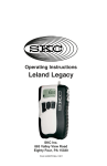
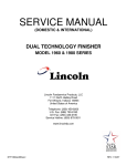
Installing New Batteries
4.
3
If replacing existing batteries, first remove batteries from
holder. Place new batteries into the holder in the following
polarity arrangement.
4
Polarity is marked
inside the
battery holder.
Back layer
Front layer
17
Battery Replacement
5.
Orient battery holder properly with
battery pack housing (black and red
wires and battery terminal toward
front of housing with SKC logo).
To avoid breakage, orient
battery holder properly and do
not force the battery holder
into the battery pack housing.
5
Front of housing with
SKC logo
Installing the New Battery Pack
1.
Align the pump case with the battery pack. The etched SKC logo should be on
the same side as the LCD and keypad. Press the two parts together until snug. The
pump will power up and the LCD will display the last mode used (typically Hold)
and possibly accumulated run time from the last sample run.
2.
Replace 2 screws on the bottom of the battery pack
housing and use a Phillips head screwdriver to tighten
screws in an alternating fashion.
Note
If the pump does not operate as expected after
replacing the battery pack, see Resetting Pump to
Manufacturer Settings.
18
2
Maintenance
Resetting Pump to Manufacturer Settings
If the pump does not operate as expected, perform the following procedure:
1. Remove the battery pack (see Removing Existing Battery
Pack).
2. On the pump keypad, press and hold Ò and T simultaneously while attaching the pump to the new battery
pack. The LCD should display the software version
2
number (525X).
Do not release hold on the two keys until the pump is firmly attached to
the battery pack.
3.
4.
5.
Release Ò and T.
Press Ò 2 times. The LCD should read 0. If it does not, repeat Steps 1 through 4
until successful.
Install 2 screws and use a Phillips head screwdriver to tighten screws in an alternating fashion.
Cautions:
• For safe operation in hazardous locations, ensure the pump label
logo and the battery pack label contains Cat.
contains the
No. P85004 or P85002. Use of any other battery pack (including
alkaline) or device to power the pump voids the UL Listing for
intrinsic safety.
•
Do not charge or operate pump from charger in hazardous
locations.
•
Use only the charger and battery packs designed for the AirChek
XR5000 pump to ensure reliable performance. Failure to do so
voids any warranty.
•
Use only SKC-approved parts to ensure reliable performance and
to maintain the UL Listing for intrinsic safety. Failure to do so voids
any warranty.
•
Tampering with the battery pack or using a repaired or rebuilt
battery pack voids any warranty and UL Listing for intrinsic safety.
•
Do not open, disassemble, short circuit, crush, incinerate, or
expose the battery to fire or high temperatures.
•
Remove alkaline batteries from pump before storage to prevent damage from battery leakage.
•
Use only the SKC-approved charger for this pump. Use of an
unapproved charger may damage the battery and pump and voids
any warranty.
•
Failure to follow warnings and cautions voids any warranty.
19
Accessories
Description
Cat. No.
Defender Primary Standard Calibrator, 50 to 5000 ml/min
flow range, includes lead-acid battery, charger (100-240 V),
software, and 1-meter serial cable
717-510M
Single Charging Kit, for models with Li-Ion battery packs only,
100-240 V AC, 50/60 Hz, includes charging unit, power supply,
and interchangeable wall plugs
223-241
Take Charge 5 Five-station Li-Ion Battery Charger for Li-Ion
model XR5000 pumps and Leland Legacy pumps, includes charging
unit and power cable, 100-240 V AC
223-441
Protective Pouches
Red, for high visibility, for high-power and alkaline models
Black, noise reducing, for high-power and alkaline models
Black, for high-power and alkaline models
Black, noise reducing, for standard model
224-96A
224-96C
224-88
224-913
Low Flow Adapter Kit (5 to 500 ml/min) Suitable for all XR5000
pump models, includes constant pressure controller (CPC), adjustable
low flow tube holder, and Type A protective tube cover
210-500
Constant Pressure Controller (CPC), for sampling in the
5 to 500 ml/min flow range. Use with adjustable low flow
holder listed below. CPC included in Low Flow Adapter
Kit (above).
224-26-CPC
Adjustable Low Flow Tube Holders for
Low Flow (5 to 500 ml/min) Sampling
Use with CPC listed above. Require separate tube covers listed below.
Single (included in Low Flow Adapter Kit above)
224-26-01
Dual
224-26-02
Tri
224-26-03
Quad
224-26-04
Sample Tube Protective Covers
Use with adjustable flow tube holders listed above.
Type A (tubes 6-mm OD x 70-mm L), included in
Low Flow Adapter Kit above
Type B (tubes 8-mm OD x 110-mm L)
Type C (tubes 10-mm OD x 150-mm L)
Type D (tubes 10-mm OD x 220-mm L)
20
224-29A
224-29B
224-29C
224-29D
Replacement Parts
Description
Cat. No.
Battery Packs
High-power Li-Ion (4-cell for UL Listed pump)
Standard Li-Ion (2-cell for UL Listed pump)
Alkaline (6-cell) - Use voids pump UL Listing for
intrinsic safety
P75715
Belt Clip
Filter (inlet)/O-ring (3)
Filter Housing
Filters, inlet (50)
Battery Pack Cover
P20139
P20140
P20142
P40011
P20419
P85004*
P85002*
* Li-Ion batteries may be subject to special shipping regulations
Cautions:
• For safe operation in hazardous locations, ensure the pump label
logo and the battery pack label contains Cat.
contains the
No. P85004 or P85002. Use of any other battery pack (including
alkaline) or device to power the pump voids the UL Listing for
intrinsic safety.
• Use only SKC-approved parts to ensure reliable performance and
to maintain the UL Listing for intrinsic safety. Failure to do so voids
any warranty.
• Any warranty and UL Listing for intrinsic safety are void if pumps
are not repaired by SKC or authorized SKC repair centers.
•
Failure to follow warnings and cautions voids any warranty.
Li-Ion Battery Shipment
Rechargeable lithium-ion batteries for use with SKC sample pumps have been tested in accordance with the UN
Manual and are proven to meet requirements of each test in the UN Manual of Test Criteria, Part III, subsection
38.3. They have a watt-hour (Wh) rating below 100.
Per 2010 IATA regulations, packaging must meet the specifications of and contain labeling and documentation
required by IATA Packing Instructions 965, 966, and 967. See IATA Guidance Document: Transport of Lithium
Metal and Lithium Ion Batteries, Revised for the 2010 Regulations
SKC Limited Warranty and Return Policy
SKC products are subject to the SKC Limited Warranty and Return Policy, which provides
SKC’s sole liability and the buyer’s exclusive remedy. To view the complete SKC Limited
Warranty and Return Policy, go to http://www.skcinc.com/warranty.asp.
21