1
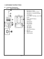
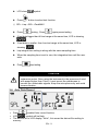
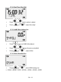
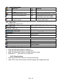
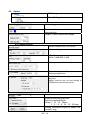
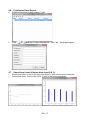
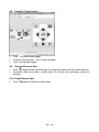
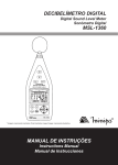
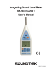
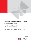
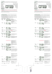
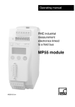
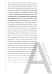
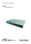
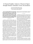
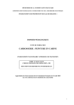
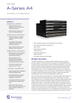
Noise Dose Meter ST-130/ST-130S User’s Manual HB2ST1300000 Contents: 1. SAFETY PRECAUTIONS ......................................................................................................... 3 1.1. Preliminary Description ..................................................................................................... 3 1.2. Note................................................................................................................................... 3 2. PREPARATION FOR USE ....................................................................................................... 4 2.1. Initial .................................................................................................................................. 4 2.2. Calibration ......................................................................................................................... 4 2.3. Storage.............................................................................................................................. 4 3. INSTRUMENT INSTRUCTIONS............................................................................................... 5 3.1. Instrument Description ...................................................................................................... 5 3.1.1. 3.1.2. 3.1.3. 3.1.4. Controls Description ................................................................................................................... 5 Display Description..................................................................................................................... 6 ST-130S Microphone.................................................................................................................. 7 Input interface ............................................................................................................................. 7 3.7.1. 3.7.2. 3.7.3. 3.7.4. 3.7.5. 3.7.6. 3.7.7. Test Mode Set ......................................................................................................................... 11 Auto Power Off Set................................................................................................................... 11 Sampling Time & Auto Record Set........................................................................................... 11 Real Time Clock Set................................................................................................................. 12 94dB Offset Adjust Set ............................................................................................................. 12 Noise Standard Set .................................................................................................................. 12 SLM Function Set .................................................................................................................... 13 4.4.1. 4.4.2. Zoom Function.......................................................................................................................... 15 Drag function ............................................................................................................................ 15 4.5.1. 4.5.2. PC Setting................................................................................................................................. 16 Meter Setting ............................................................................................................................ 16 7.2.1. 7.2.2. Environmental Conditions......................................................................................................... 23 EMC.......................................................................................................................................... 23 3.2. 3.3. 3.4. 3.5. 3.6. 3.7. 4. Noise Does Measurement Procedures ............................................................................. 8 Sound Level Measurement Procedures ............................................................................ 8 Auto Data Record.............................................................................................................. 9 Single Data Record ......................................................................................................... 10 Viewing Logged Reading ................................................................................................ 10 Set Mode ......................................................................................................................... 10 SOFTWARE............................................................................................................................ 14 4.1. System Requirements ..................................................................................................... 14 4.2. Software Description ....................................................................................................... 14 4.3. Tools Description............................................................................................................. 15 4.4. Open File......................................................................................................................... 15 4.5. Option.............................................................................................................................. 16 4.6. Print Noise Dose Report.................................................................................................. 17 4.7. Sound level chart & Noise dose chart (LN %) ................................................................. 17 4.8. Enable PC data logger .................................................................................................... 18 4.9. Dowload Record data...................................................................................................... 18 4.10. Erase Record data .......................................................................................................... 18 5. EXPLAINATION ...................................................................................................................... 19 5.1. 1. Measurement Parameters:.......................................................................................... 19 5.2. A, C, Z Weighting Instruction:.......................................................................................... 20 6. MAINTENANCE ...................................................................................................................... 21 6.1. General Information......................................................................................................... 21 6.2. Battery Replacement....................................................................................................... 21 6.3. Cleaning .......................................................................................................................... 21 6.4. End of Life ....................................................................................................................... 21 7. TECHNICAL SPECIFICATIONS............................................................................................. 22 7.1. Feature ............................................................................................................................ 22 7.2. Environment .................................................................................................................... 23 7.3. Accessories ..................................................................................................................... 23 8. 7.3.1. Standard Accessories............................................................................................................... 23 SERVICE ................................................................................................................................ 24 8.1. Warranty Conditions........................................................................................................ 24 8.2. Service ............................................................................................................................ 24 EN - 2 1. SAFETY PRECAUTIONS When taking measurements: ․ Avoid doing measurements in humid or wet places - make sure that humidity is within the limits indicated in section “environmental conditions”. ․ Avoid doing measurements in presence of explosive gas, combustible gas, steam or excessive dust. The following symbols are used: Caution: refer to the user’s manual. An incorrect use may damage the tester or its components The instrument conforms to the CE standard 1.1. Preliminary Description The ST-130/ST-130s is designed to test noise exposure in accordance with OSHA,MSHA,DOS,ACGIH, and ISO standards. Fast and easy on-site surveys help determine noise reduction requirements. The meter can also be used in SLM(sound level meter)mode. The SLM mode has a datalogging feature that can record up to 1000K readings which can be downloand to PC for analysis. The built-in USB interface to connect PC. Applications: Evaluation of environmental noise, Measurements of noise at workplaces, Assessment of product noise. 1.2. Note CAUTION Does not observe the warning and/or operation instruction, it’s possible to damage the instrument either its components or the operator Do not operate the instrument at temperature and humidity environment beyond to reference conditions of chapter 7.2.1. ․ Keep the microphone dry and avoid severe vibration. ․ Wind blowing across the microphone would bring additional extraneous noise. Once using the instrument in the presence of wind, it must mount the windscreen to prevent the undesirable signals. ․ EN - 3 2. PREPARATION FOR USE 2.1. Initial The instrument has been checked mechanically and electrically prior to shipment. Take care to ensure the instrument reaches you undamaged. However, it is wise to carry out a rapid check in order to detect any possible damage that may cause during transport. If it’s damage, claims to the dealer immediately. Check the packaging content according to packing list reported in 7.3.1 chapter .In case of discrepancies, contact the dealer immediately. In the event of re-shipment of the instrument please follow the instructions reported in chapter 7.3.1. 2.2. Calibration The instrument complies with the technical specifications contained in this manual and such compliance is guaranteed for 1 year. The instrument is maybe need recalibration after one year. 2.3. Storage After a period of storage in extreme environmental conditions exceeding the limits mentioned in paragraph 7.2.1 let the instrument return to normal measuring conditions before using it. EN - 4 3. INSTRUMENT INSTRUCTIONS 3.1. Instrument Description 3.1.1. Controls Description 1. 2. 3. 4. 5. 6. 7. 8. 9. 10. 11. 12. 13. 14. 15. 16. 17. 18. EN - 5 Microphone Microphone Cable Microphone Connector(Male) Microphone Connector(Female) LCD Display record data / Reading record data button Power ON/OFF Button UP Button Right Button Enter Button Down Button Left Button SET Button Stop Button Start /Pause Button Belt clip Battery Cover USB Interface 3.1.2. Display Description Battery Status Auto Power Off Enable Pause 115dB Stop 140 dB indicator(SPL) indicator(Peak) USB Interface Start SPL High dB Range (140~70) dB Display SPL Middle dB Range (110~50) Testing mode SPL Low dB Range (90~30) Noise Dose % Sound Level Meter mode Sound Noise dB A Weighting Fast Weighting C Weighting Slow Weighting Z Weighting Impulse Weighting dB test data > Hi level dB test data < Low level Start test time Solid: Auto record standby: Flashing recording Visit record data SET mode turn on Stop test time Test duration EN - 6 ․ ․ ․ ․ ․ 3.1.3. ST-130S Microphone Diameter : 1/2 inch Polarization voltage : 0V Dynamic range : 25dBA ~140dB Sensitivity : -32±3dB (250Hz 0dB=1V/Pa) Free field frequency response : ±2dB(25Hz~12.5kHz) Frequency (KHz) 0.25 1 2 3 4 5 6 7 8 9 10 12.5 Deviation of pressure 0.0 -0.1 -0.5 -0.6 -0.9 -1.2 -1.7 -2.2 -2.8 -3.3 -4.1 -6.0 3.1.4. Input interface The front is PLT84RFR, the signal input receptacle. ST-130 Pin 1 GND Pin 2 Power Pin 3 NC Pin 4 NC ST-130S Pin 1 GND Pin 2 Power(+) Pin 3 N.C Pin 4 Power(-) EN - 7 3.2. Noise Does Measurement Procedures Press turn on meter LCD do not display Press testing. Press symbol. turn on noise dose testing. ,press again pause select testing information ◎ SPL→Dose%→LPMAX→LPMIN→PKMAX→LEQ→SEL→LEP8→TWA8→ LVAG→LN% to observe testing date information. Press Press date display information. ◎ Time(hh:mm:ss)→date(YY-DD-MM) 3.3. Press stop testing and store all test data Sound Level Measurement Procedures Press turn on meter EN - 8 change LCD show Press symbol button to select test function. ◎ SPL→Leq→SEL→PeakMAX Press If test data bigger than HI test range at the same time, LCD is showing If test data is smaller than Low test range at the same time, LCD is testing , Press again pause testing showing Leq integral time setting is along with the same sampling time. When the sampling time is set to zero, the integration time until the user exits Press stop testing CAUTION Wind blowing across the microphone would bring additional extraneous noise. Once using the instrument in the presence of wind with speed higher than 10m/s, it must mount the windscreen to prevent the undesirable signals. Keep the microphone dry and avoid severe vibration. 3.4. Auto Data Record ․ Press enabled Auto record function. symbol will be flash. ․ LCD ․ The bottom left of LCD display ”Write” , this mean the data will be writing to memory. EN - 9 ․ The bottom left of LCD display “FULL”, this mean the data will be full. ․ Auto record function can not use menu record. 3.5. Single Data Record ․ Press each time to store the display reading and symbol flash. ․ The bottom left of LCD display ”Write” , this mean the data will be writing to memory. 3.6. Viewing Logged Reading ․ Press button more than 1 sec into the viewing logged reading mode. ․ Press or ․ Press to scroll through the readings. select dose record information. (Nosie Dose Meter mode) ◎ Test model→Start time→Test duration time →Total pause time→Test end time ․ Press to change data or date, Press (hh:mm:ss→YY-MM-DD) ․ Press change Time. more than 1 sec again to exit viewing logged reading mode. 3.7. Set Mode ․ Press into set mode , can set 7 functions in set mode ․ Press exit set mode ◎ Test Mode→Auto Power Off→Sampling Time & Auto Record→Real Time Clock→94dB Offset Adjust→Noise standard→SLM Fuunction ․ Press again,save set and into next set mode EN - 10 3.7.1. Test Mode Set ․ Press or ◎ NDM: Noise Dose Meter ◎ SLM:Sound Level Meter , change test mode. (NDM →SLM) 3.7.2. Auto Power Off Set ․ Press or , enable or disable Auto Power Off function 3.7.3. Sampling Time & Auto Record Set ․ ․ ․ Press or , select auto records set or sampling time. or enable or disable Auto record, adjust sampling time. Press Minimum sampling time: 1 second; Maximum sampling time: 23 hours 59 minutes 59 seconds EN - 11 3.7.4. Real Time Clock Set ․ Press ․ ․ Press or , select option to adjust. or , adjust time digit. 3.7.5. 94dB Offset Adjust Set ․ Press ․ Press ․ Press , auto run 94dB offset adjust. or , change frequency weighted or , adjust offset 3.7.6. Noise Standard Set ․ Press or ,select NDM testing law ◎ OSHA→MSHS→DOD→ACGIH→ISO85→ISO90→USER EN - 12 3.7.7. SLM Function Set ․ Press ◎ → ◎ or , change test function → → → → → ◎ ◎ Peak C →Peak Z or ,select test function ․ Press ◎ Sound level range→Time weighted→Frequency weighted→Peak frequency EN - 13 4. SOFTWARE 4.1. System Requirements Operating: Windows® XP/Windows Vista/Windows 7/Windows 8 Storage:200 MB of available hard disk space. Processor: Intel Pentium® 4 Memory:1 GB RAM (XP), 1.5 GB (Windows Vista/Windows 7/Windows 8) Other: PL2303 Windows Drive ;Microsoft .NET Framework 3.5 Service Pack 1 4.2. Software Description EN - 14 4.3. Tools Description Open file Print noise dose report (*.ndr) Noise dose chart (LN%) Stop to log sound level Options Sound level chart Start to log sound level (*.csv) Download sound level logs; Doenload noise does report Automatic detect port which connect with meter Erase measured data that stored in meter 4.4. Open File Sound Level Log List Tool SPL→LEQ→SEL→PeakMax Fast→Slow→Impluse A→C→Z Calculate LEQ & SEL Save file as…. Graph Sound Level Logs Graph Zoom Drag Print Print Preview Print Setup ․ ․ ․ ․ 4.4.1. Zoom Function Click the left mouse button to zoom in Click the left mouse button to original size Hold the left mouse button to moving selection range Keyboard '+', '-' can zoom in or zoom out 4.4.2. Drag function ․ Hold the left mouse button can moving view range ․ Hold CTRL+ left mouse button can be change view range and zoom EN - 15 4.5. Option PC Setting Meter Setting 4.5.1. PC Setting PC data logger sample time. Click the left mouse button to change the color box Graph (Y-axis) sound level range 4.5.2. Meter Setting Serial number(0~9;A~Z)16 word Alarm setting dB Offset setting MAX:+3.9dB MIN:-3.9dB Setting meter real time clock Enable/disable auto Record. Setting sample time Enable/disable auto play noise dose function. Meter must be turn on and setting in NDM(noise does meter) mode Select noise dose standard Select noise dose play time. Default standard(8hour), Other 5;10;15;30min 1;2 ;4;8;10;12;24 hour Setting information import or export ,file format(*.ncg) EN - 16 4.6. Print Noise Dose Report Select noise dose logger report (*.ndr) Click or and key in user information , click “ok” ,the output report 4.7. Sound level chart & Noise dose chart (LN %) Sound level char. X-axis is the time coordinate.Y-axis is the sound coordinate. Noise does chart. X-axis is the LN%. Y-axis is the sound coordinate. EN - 17 4.8. Enable PC data logger Click enable data logger. Create a new log file (*. csv) in the hard disk. stop data logger. Click 4.9. Dowload Record data Click download sound level logs or noise dose report on the meter memory. Download 100K record data. it takes about 15 minutes time-consuming, please be patiently. 4.10. Erase Record data Click delete all records of the meter. EN - 18 5. EXPLAINATION 5.1. 1. MEASUREMENT PARAMETERS: Test Function Screen parameter Explaination SPL LAFp Sound pressure level (SPL) SPL LASp Sound pressure level (SPL) SPL LCFp Sound pressure level (SPL) SPL LCSp Sound pressure level (SPL) SPL LZFp Sound pressure level (SPL) SPL LZSp Leq LAFq Sound pressure level (SPL) Equivalent continuous level for the duration of the measurement for A weighting Leq LCFq Equivalent continuous level for the duration of the measurement for C weighting LZFq Equivalent continuous level for the duration of the measurement for Z weighting LAE Frequency weighted sound exposure level for the duration of the measuremen for A weighting SEL LCE Frequency weighted sound exposure level for the duration of the measuremen for C weighting SEL LZE Frequency weighted sound exposure level for the duration of the measuremen for A weighting Peak Lcpeak Leq SEL Instantaneous C peak level EN - 19 5.2. A, C, Z WEIGHTING INSTRUCTION: 1. : The A weighting curve is based on 40 Phon Fletcher-Munson Equal Loudness Contour, Noise assessment in human, suggest to use the A weighting. 2. The C weighting in essentially is approximate smooth. With labor safety concern, suggest using the C weighting. 3. The Z weighting for the electric instrument interior not the linear signal which processes after the filter, suits in wants to output AC or the DC signal does other research to use. The Z weighting is a linear signal which is not processed through the filter. It’s suitable to output AC or DC signal for research. 4. Sound Level Meter Class Description: Class 0: use in the laboratory reference standard. Class 1: laboratory or field use. Class 2: laboratory or field use. Class 3: general field use. EN - 20 6. MAINTENANCE 6.1. GENERAL INFORMATION This is a precision instrument. To guarantee its performance be sure to use it or keep it stored on suitable environmental conditions. Do not expose it to high temperatures or humidity or direct sunlight. Be sure to turn the power off after use. If you expect not to use the instrument for a long period remove batteries to avoid leakages of battery liquid which could damage the its inner components. 6.2. BATTERY REPLACEMENT The low battery “ 6.3. ” indication is displayed; the battery should be replaced. Turn off the instrument. Remove the battery cover. Remove all the batteries from the battery holder. Insert four new batteries of the same type respecting the polarity signs. Install the battery cover. Please follow the local laws and regulations to process the waste battery. CLEANING To clean the instruments use a soft dry cloth. Never use a wet cloth, solvents or wate. 6.4. END OF LIFE Caution: this symbol indicates that equipment and its accessories shall be subject to a separate collection and correct disposal. EN - 21 7. TECHNICAL SPECIFICATIONS 7.1. FEATURE Environmental conditions: temperature 23℃ ± 5℃, relative humidity < 80%. Display Single LCD MAX reading 999999 Display Refresh Rate 1 Time/sec Standards IEC 61252-1993 IEC 61672-1-2003 ANSI S1,25-1992 ANSI S1,4-1983 ANSI S1,43-1997 Microphone(ST-130S) Microphone(ST-130) Measurement Items(SLM) Primary @1KHZ 1/2 inch Electret condenser microphone Does%,Lxyp,Lxmax,Lxmin,Lxeq,SEL(LAE),PeakMAX,L AVG,TWA,LEP,LN% Measurement Items(NDM) Display 1/2” pre-polarized condenser microphone build in preamplifier: 1V/Pa@250HZ, frequency range: 20 Hz~12.5 kHz, Thermal noise: <25 dB(A) Lxyp,Lxmax,Lxmin,Lxeq,SEL(LAE),PeakMAX 30dB to 90dB (L) 50dB to 110dB (M) 70dB to 140dB (H) Range RMS 41dB to 86dB (L) 55dB to 106dB (M) 75dB to 125dB (H) Range Maximum Peak C Weighting Sound Level Measurement 90~143 dB Dynamic Range Accuracy 60 dB ±1.4dB@94dB /1KHZ Internal memory MAX Datalogger data:10000(NDM);999999(SLM) Time Weighting Fast, Slow, Impulse Frequency Weighting A/C/Z Frequency Range 20Hz~8KHz Starting Time <10 Second Battery Life(ST-130) 24 hours ( 9V×1 battery Alkaline ) Battery Life(ST-130S) 20 hours ( 9V×1 battery Alkaline ) Dimensions 107(L) x 65(W) x 33(H) mm EN - 22 7.2. ENVIRONMENT ․ ․ ․ ․ ․ ․ 7.2.1. Environmental Conditions For inside use, max height: 2000m Reference temperature: 23° ± 5℃ Operation temperature: 5 ~ 40 ℃ Operation humidity: <80% RH Storage temperature -10 ~ 60 ℃ Storage humidity <70% 7.2.2. EMC This instrument was designed in accordance with EMC Standards in force and its compatibility has been tested in accordance with EN61326-2 (2006). 7.3. ACCESSORIES 7.3.1. Standard Accessories Noise Dose Meter. User’s manual. Carrying case. 9 V battery 、NEDA 1604 、IEC 6F22 or JIS 006P. Microphone diameter windscreen. Software. MINI USB Cable (Mini B type). EN - 23 8. SERVICE 8.1. WARRANTY CONDITIONS This instrument is guaranteed for one year against material or production defects, in accordance with our general sales conditions. During the warranty period the manufacturer reserves the right to decide either to repair or replace the product. Should you need for any reason to return back the instrument for repair or replacement take prior agreements with the local distributor from whom you bought it. Do not forget to enclose a report describing the reasons for returning (detected fault). Use only original packaging. Any damage occurred in transit due to nonoriginal packaging will be charged anyhow to the customer. The warranty doesn’t apply to: Accessories and batteries (not covered by warranty) Repairs made necessary by improper use (including adaptation to particular applications not foreseen in the instructions manual) or improper combination with incompatible accessories or equipment. Repairs made necessary by improper shipping material causing damages in transit. Repairs made necessary by previous attempts for repair carried out by non-skilled or unauthorized personnel. Instruments for whatever reason modified by the customer himself without explicit authorization of our Technical Dept. The contents of this manual may not be reproduced in any form whatsoever without the manufacturer’s authorization. Our products are patented. The logotypes are registered. We reserve the right to modify characteristics and prices as part of technological developments which might require them. 8.2. SERVICE Shouldn’t the instrument work properly, before contacting your distributor make sure that batteries are correctly installed and working, check the test leads and replace them if necessary. EN - 24 TENMARS ELECTRONICS CO., LTD 6F, 586, RUI GUANG ROAD, NEIHU, TAIPEI 114, TAIWAN. E-mail: [email protected] http://www.tenmars.com