1
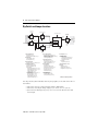
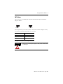
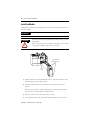
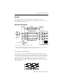
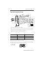
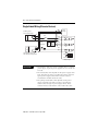
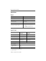
Installation Instructions
High-Speed Counter Module
(Catalog Number 1746-HSCE)
Inside ................................................................................................Page
For More Information............................................................................... 3
Hazardous Location Considerations ........................................................ 4
Environnements dangereux ..................................................................... 4
High-Speed Counter Module Overview................................................... 5
Dip Switch and Jumper Locations ........................................................... 6
Install the Module.................................................................................. 10
Remove the Terminal Block.................................................................... 11
Wire the Removable Terminal Block...................................................... 11
Important Wiring Considerations .......................................................... 12
Input and Output Connections ............................................................... 13
Outputs................................................................................................... 14
Encoders................................................................................................. 15
Single-Ended Wiring (Discrete Devices)................................................ 18
Limit Switch Wiring ............................................................................... 19
Specifications ........................................................................................ 20
Publication 1746-IN011C-EN-P - April 2005
2
High-Speed Counter Module
Important User Information
Solid state equipment has operational characteristics differing from those of electromechanical equipment.
Safety Guidelines for the Application, Installation and Maintenance of Solid State Controls (Publication
SGI-1.1 available from your local Rockwell Automation sales office or online at
http://www.ab.com/manuals/gi) describes some important differences between solid state equipment and
hard-wired electromechanical devices. Because of this difference, and also because of the wide variety of
uses for solid state equipment, all persons responsible for applying this equipment must satisfy themselves
that each intended application of this equipment is acceptable.
In no event will Rockwell Automation, Inc. be responsible or liable for indirect or consequential damages
resulting from the use or application of this equipment.
The examples and diagrams in this manual are included solely for illustrative purposes. Because of the many
variables and requirements associated with any particular installation, Rockwell Automation, Inc. cannot
assume responsibility or liability for actual use based on the examples and diagrams.
No patent liability is assumed by Rockwell Automation, Inc. with respect to use of information, circuits,
equipment, or software described in this manual.
Reproduction of the contents of this manual, in whole or in part, without written permission of Rockwell
Automation, Inc. is prohibited.
Throughout this manual, when necessary we use notes to make you aware of safety considerations.
WARNING
Identifies information about practices or circumstances that can cause an explosion in a
hazardous environment, which may lead to personal injury or death, property damage,
or economic loss.
IMPORTANT
Identifies information that is critical for successful application and understanding of the
product.
ATTENTION
Identifies information about practices or circumstances that can lead to personal injury
or death, property damage, or economic loss. Attentions help you:
• identify a hazard
• avoid a hazard
• recognize the consequence
SHOCK HAZARD
Labels may be located on or inside the equipment (e.g., drive or motor) to alert people
that dangerous voltage may be present.
BURN HAZARD
Labels may be located on or inside the equipment (e.g., drive or motor) to alert people
that surfaces may be dangerous temperatures.
Publication 1746-IN011C-EN-P - April 2005
High-Speed Counter Module
3
For More Information
Related Publications
For
Refer to this Document
Pub. No.
A more detailed description on how to
configure and program the High-Speed
Counter Module.
High-Speed Counter Module
User Manual
1746-6.5
A more detailed description on how to install
and use your modular SLC™ 500 system.
SLC 500 Modular Hardware
Style Installation and
Operation Manual
1747-UM011
A reference manual that contains status file
data, instruction set, and troubleshooting
information.
SLC 500 Instruction Set
Reference Manual
1747-RM001
To view and download pdfs, go to Literature Library at
http://www.rockwellautomation.com/literature.
To order printed copies, contact your Allen-Bradley® Distributor or Rockwell
Automation® Sales Office.
Publication 1746-IN011C-EN-P - April 2005
4
High-Speed Counter Module
Hazardous Location Considerations
This equipment is suitable for use in Class I, Division 2, Groups A, B, C, D or
non-hazardous locations only. The following WARNING statement applies to use in
hazardous locations.
WARNING
EXPLOSION HAZARD
• Substitution of components may impair suitability for Class
I, Division 2.
• Do not replace components or disconnect equipment
unless power has been switched off or the area is known to
be non-hazardous.
• Do not connect or disconnect components unless power
has been switched off or the area is known to be
non-hazardous.
• All wiring must comply with N.E.C. article 501-4(b).
Environnements dangereux
Cet équipement est conçu pour être utilisé dans des environnements de Classe I,
Division 2, Groupes A, B, C, D ou non dangereux. La mise en garde suivante
s’applique à une utilisation dans des environnements dangereux.
AVERTISSEMENT
DANGER D’EXPLOSION
• La substitution de composants peut rendre cet équipement
impropre à une utilisation en environnement de Classe I,
Division 2.
• Ne pas remplacer de composants ou déconnecter
l'équipement sans s'être assuré que l'alimentation est
coupée.
• Ne pas connecter ou déconnecter des composants sans
s'être assuré que l'alimentation est coupée.
Publication 1746-IN011C-EN-P - April 2005
High-Speed Counter Module
5
High-Speed Counter Module Overview
The High-Speed Counter Module, Catalog Number 1746-HSCE is an SLC 500 family
compatible device except with the 1747-ASB Remote I/O Adapter Module. It can be
used with SLC™ 5/02 (and above) processors.
The module’s bidirectional counting ability allows it to detect movement in either
direction. In addition, x2 and x4 counting modes are provided to fully use the
capabilities of high-resolution quadrature encoders.
High-speed inputs from quadrature encoders and various high-speed switches are
supported. Accepting input pulse frequencies of up to 50k Hz allows precise
control of fast motions.
In addition, an Accumulated Counter, the module provides a Rate Counter to
determine Rate Measurement by indicating the pulse input frequency in Hz. (See
the block diagram on page 6.) The Rate Measurement is determined by
accumulating input pulses over a fixed period of time. You set the Rate Period to
best match your application requirements.
Background Rate calculation is provided in Sequencer and Range Modes. This
operation accepts input rates up to 32,767 Hz. The dynamically configurable Rate
Period ranges from 10 ms to 2.55 seconds.
The module’s four current sink (open collector) outputs can be controlled in the
user program or the module.
Control of the counter reset is configured through user-set parameters. The counter
can be reset from any combination of the Z input, Limit Switch input, or Soft Reset
control bits.
Module operation is determined by selections made in the Setup and Control Word
(M0:e.1). Setting the Function Control bit to 1 triggers the module to start the
proper pulse counter, rate measurement, and output control functions. Many
parameters are dynamic and can be changed without disrupting counter operation.
The module’s block diagram is shown on page 6. Inputs from the terminal block
enter the diagram at the left, outputs to the terminal block exit at the right. M0 and
Output file parameters from the SLC enter the logic blocks from the top. Input file
data to the SLC exit the logic blocks from the bottom.
Publication 1746-IN011C-EN-P - April 2005
6
High-Speed Counter Module
Dip Switch and Jumper Locations
Counter Input
Parameters
Rate Period Parameters
Z
LS
LS Filter (JW1)
Input
Logic
Rate
Counter
Pulse and Direction
Operating Mode Logic
Reset Parameters
Reset
Logic
Rate
Counter
Inputs
Reset Condition
Output Control
Parameters
Rate Measurement
Rate
Operating
Mode
Outputs
Output
Control
Logic
4
Physical
Outputs
Sequencer
Pulse Counter Parameters
Output
Status
Inputs
Range
Pulse
Counter
Reset
Input
Bit
Counter Input Parameters
Input Type (M0:e.1/9–11)
Up/Down Count Direction (M0:e.1/3) –d
Reset Parameters
Soft Reset bit (M0:e.1/4) –d
Reset Mode (M0:e.1/5–7)
Rate Period Parameters
Rate Period (M0:e.9/0–7 or M0:e.16/0–7) –d
To Terminal Block
From Terminal Block
Operating Mode Parameters
A
B
Accumulated Count
Operating
Mode
Inputs
Pulse
Counter
Inputs
Pulse Counter Parameters
Reset Value (M0:e.34 or M0:e.41) –d
Maximum Count Value (M0:e.34 or M0:e.41)
Counter Hold bit (M0:e.1/2) –d
Counter Type bit (M0:e.1/13)
Output Control Parameters
Direct Outputs (O:e.0/0–7) –d
Output Source Select (M0:e.0/0–7) –d
Enable Outputs bit (M0:e.1/1) –d
Reset Input bit (I:e.0/12)
Operating Mode Inputs
Sequencer Inputs
Current Sequencer Step (I:e.5/0–7)
Next Sequencer Step (I:e.5/8–15)
Sequence Done (I:e.0/6)
Range inputs
Ranges Active (I:e.6/0–11)
Output Status Inputs (I:e.4/8–15)
Operating Mode Parameters
Operating Mode (M0:e.1/14–15)
Function Control Bit (M0:e.1/12)
Range Definitions:
Range Starting Values (M0:e.10 – 33) –d
Range Ending Values (M0:e.10 – 33) –d
Range Outputs (M0:e.3 – 8) –d
Valid Ranges (M0:e.2) –d
Sequencer Definitions:
Valid Steps (M0:e.2 and M0:e.3/0–7) –d
Step Presets (M0:e.17 – 40) –d
Step Outputs (M0:e.4 – 15) –d
Initial Outputs (M0:e.3/8–15) –d
Sequencer Reset (M0:e.1/0) –d
Rate Counter Inputs
Rate Valid (I:e.0/3)
Rate Counter Overflow (I:e.0/4)
Rate Measurement Overflow (I:e.0/5)
Zero Rate Period Count (I:e.0/2)
Rate Period Count (I:e.2)
Rate Measurement (I:e.3)
Error Inputs
Critical Error (I:e.0/10)
Configuration Error bit (I:e.0/11)
Configuration Error Code (I:e.4/0–7)
Pulse Counter Inputs
Accumulated Count (I:e.1)
Overflow/Underflow (I:e.0/13)
Pulse Counter State (I:e.0/14–15)
–d indicates a dynamic parameter
Two dip switches (SW1 and SW2) and one jumper (JW1) are located on the side of
the module.
• SW1 selects the type of input (single ended or differential).
• SW2 selects the output voltage range (4.5 to 10V dc or 10 to 30V dc).
• JW1 selects the filtering rate (300 µs or 10 ms) used to debounce the limit
switch input.
Publication 1746-IN011C-EN-P - April 2005
High-Speed Counter Module
7
Default settings are shown below:
O
N
1 234
SW 2
SW 2
JW 1
JW 1
SW2 Default
10 to 30V dc
3
JW1
1
JW1 Default
10 ms filter
O
N
1234
SW 1
SW1 Default
Single-ended
ATTENTION
Use a small screwdriver to change dip switch positions.
Graphite from pencils will damage the switch.
Publication 1746-IN011C-EN-P - April 2005
8
High-Speed Counter Module
SW2 Settings
Select an output voltage range that coincides with your supply voltage. The
selections are 4.5 to 10V dc or 10 to 30V dc.
ON
OFF
1234
10 to 30V dc
1234
ON
OFF
Switch
1
2
3
4
Output
0
1
2
3
4.5 to 10V dc
All switches of SW2 must be ON or all switches must be OFF.
Permanent damage may result if some are ON and some are
OFF.
ATTENTION
Operating in the 10 to 30V dc range with the switches set for the
4.5 to 10V dc range damages the module.
SW1 Settings
Select a single-ended or differential input connection.
ON
1234
OFF
Dip switch SW1
Position
Switch
1
2
3
4
Channel
A
B
Z
not used
Input Connection
Input ON Range
ON
differential
2.8 to 4.5V dc
OFF
single-ended
3.1 to 5.5V dc
You can configure different inputs in different modes. For example, input A (CHA)
can be configured as differential and input Z (CHZ) can be configured as
single-ended.
Publication 1746-IN011C-EN-P - April 2005
High-Speed Counter Module
9
JW1 Settings
Select 300 µs or 10 ms filtering to debounce the limit switch input. Position the
jumper as follows:
321
32 1
JW 1
JW 1
10 ms filter
300 µs filter
The LS input allows you to make a direct connection to nominal voltage levels of 5,
12, or 24V dc. The ON voltage ranges are as follows:
Wiring Terminal
ON Range
LS (24V dc)
16.5 to 30V dc
LS (12V dc)
9.4 to 16.5V dc
LS (5V dc)
3.8 to 5.5V dc
See page 19 for limit switch wiring instructions.
ATTENTION
Connect only one LS input range at a time, or the module will
be damaged.
Publication 1746-IN011C-EN-P - April 2005
10
High-Speed Counter Module
Install the Module
Installation procedures for this module are the same as for any other discrete I/O or
specialty module.
IMPORTANT
Set the dip switches before installing the module.
ATTENTION
Disconnect power before attempting to install, remove, or wire
the module.
Make sure your SLC power supply has adequate reserve current
capacity. The module requires 320 mA at 5V dc.
Top and Bottom
Module Release(s)
Card
Guide
1. Align the full-size circuit board with the chassis card guide. The first slot of
the first chassis is reserved for the CPU.
2. Slide the module into the chassis until the top and bottom latches are
latched.
Make sure the removable terminal wiring block is attached to the module
and all wires are connected to the terminal block.
3. Insert the cable tie in the slots and secure the cable.
4. Cover all unused slots with the Card Slot Filler, Catalog Number 1746-N2.
Publication 1746-IN011C-EN-P - April 2005
High-Speed Counter Module
11
Remove the Terminal Block
The removable terminal wiring block eliminates the need to rewire a module if it is
removed from the chassis. Each terminal accepts two #14 AWG wires.
ATTENTION
Disconnect power before attempting to install, remove, or wire
the removable terminal wiring block.
To avoid cracking the removable terminal block, alternate the
removal of the slotted terminal block release screws.
Remove the terminal block by turning the slotted terminal block release screws
counterclockwise. The screws are attached to the terminal block, so it will follow as
the screws are turned out.
Wire the Removable Terminal Block
Use a flat or cross slot screwdriver to tighten terminal screws. Each screw should be
turned tight enough to immobilize the wire’s end. Overtightening can strip the
terminal screw. Do not exceed 0.7 to 0.9 Nm (6 to 8 in-lbs.).
Publication 1746-IN011C-EN-P - April 2005
12
High-Speed Counter Module
Important Wiring Considerations
Use the following guidelines when planning the system wiring for the module:
•
•
•
•
•
•
•
•
Install the SLC 500 system in a NEMA-rated enclosure.
Disconnect power to the SLC processor and the module before wiring.
Make sure the SLC 500 system is properly grounded.
Group this module and low-voltage DC modules away from AC I/O or
high-voltage DC modules.
Shielded cable is required for high-speed input signals A, B, and Z. We
recommend Belden 9503 or equivalent for lengths up to 305 m (1000 ft).
When the LS input is driven by an electromechanical device, route the
wiring away from other inputs. In addition, JW1 should be set for the 10 ms
filter.
When the LS input is driven by a solid-state device, use a shielded cable.
You do not have to route the cable away from other inputs.
Shields should be grounded only at the end of the signal source end of the
cable. Ground the shield to the case of the signal source, so energy coupled
to the shield will not be delivered to signal source’s electronics.
Publication 1746-IN011C-EN-P - April 2005
High-Speed Counter Module
13
Input and Output Connections
Input and output wiring terminals are located on the front of the module, behind
the terminal cover. When you connect input and output devices, you must also be
concerned with the settings of dip switch SW1 (input connections), dip switch SW2
(output connections), and jumper JW1 (limit switch input connections). The
location and description of these are shown on pages 6 through 9.
OUTPUT
0
1
2
3
Upper Retaining Screw Maximum
Torque = 0.7 to 0.9 Nm (6 to 8 in-lbs)
Discrete Output Wiring
NOTE: V dc must be externally
supplied by the user. See
page 14 for output wiring.
Terminal Wiring
max. 2 wires per terminal
max. torque: 0.9 Nm (8 in-lbs)
Limit Switch and
Encoder Input Wiring
See pages 15 through 19 for
input wiring.
VDC
OUT 0
OUT 1
OUT 2
OUT 3
DC COM
A+
B+
ABNot used
Not used
Z+
LS (24 VDC )
ZLS (12 VDC )
LS COM
LS (5 VDC )
INPUT
4
5
6
7
A
B
Z
LS
FAULT
HSCE
VDC
OUT 0
OUT 1
OUT 2
OUT 3
A+
DC
COM
B+
ANot
Used
Z+
ZLS
COM
BNot
Used
LS
(24V dc)
LS
(12V dc)
LS
(5V dc)
Lower Retaining Screw Maximum
Torque = 0.7 to 0.9 Nm (6 to 8 in-lbs)
Publication 1746-IN011C-EN-P - April 2005
14
High-Speed Counter Module
Outputs
The module features four physical outputs. They can be controlled by the module
when certain counter conditions are met, or they can be controlled from the user
program (refer to the High-Speed Counter Module User Manual, publication
1746-6.5 for M0:e.0 information).
The outputs are bipolar transistors connected in a sinking (open collector sinking)
configuration. When the output is energized, it sinks the current.
Do not use incandescent lamps as output indicators. The high
peak inrush current required to heat the filament can damage
the module’s output circuits. Use LED indicators that satisfy the
output circuit ratings, such as Allen-Bradley 800A and 800T LED
indicators.
ATTENTION
You can select an output voltage range of 4.5 to 10V dc or 10 to 30V dc. Refer to
page 21 for the maximum current specifications for each voltage range. Dip switch
SW2, located on the PC board, is used to select the voltage range. See pages 6 and
8 for switch SW2 location and settings.
The figure below indicates wiring connections for four 24V dc outputs. All switches
of SW2 are OFF for this output voltage.
VDC
OUT 0
User Supplied
24V dc
+
OUT 1
-
OUT 2
All switches OFF
ON
OUT 3
DC COM
1 234
OFF
Dip Switch SW2
wiring terminals
HSCE module
The outputs are not electrically isolated from each other. (They are referenced to
the same output common terminal.) However, outputs are isolated from the rest of
the circuitry to a level of 1500 volts.
Publication 1746-IN011C-EN-P - April 2005
High-Speed Counter Module
15
Encoders
The wiring diagrams on the following pages are provided to support the
Allen-Bradley encoders you may already have. Differential encoders provide the
best immunity to electrical noise.
Differential Encoder Wiring
cable (1)
+ V DC
COM
VS
GND
Belden 9503 or equivalent
305m (1000ft) max length
Allen-Bradley
845H Series
differential
encoder
A
A(+)
A
A(-)
B
B(+)
B
B(-)
Z
Z(+)
Z
Z(-)
Power
Supply
Shield(2)
SW1
encoder connector
Earth
ON 1 2 3 4
OFF
(all switches
Module Inputs
(1) Refer to your encoder manual for proper cable type and length.
(2) Due to the topology of the module’s input circuits, terminating the shield at the encoder end provides the highest immunity
to EMI interference. Connect EARTH ground directly to the encoder connector housing.
Differential Encoder Output Waveforms
The illustration below shows the different encoder output waveforms. If your
encoder matches these waveforms, the encoder signals can be directly connected to
the associated screw terminals on the module. For example, the A lead from the
encoder is connected to the module’s A+ screw. If your encoder does not match
these waveforms, some wiring modifications may be necessary. Refer to the
High-Speed Counter Module User Manual, publication 1746-6.5 for a description of
these modifications.
A
A
B
B
Z
Z
Publication 1746-IN011C-EN-P - April 2005
16
High-Speed Counter Module
Single-Ended Encoder Wiring (Open Collector)
cable(1)
VS
GND
+ VDC
COM
Power
Supply
(3)
R
Allen-Bradley
845H Series
single-ended
encoder
Shield(2)
A
A(+)
A(-)
B
B(+)
B(-)
Z(+)
Z(-)
Z
Belden 9503 or equivalent
305m (1000tft) max length
encoder connector housing
ON
SW1
1 234
OFF
(All switches OFF)
Module Inputs
Earth
(1) Refer to your encoder manual for proper cable type and length.
(2) Due to the topology of the module’s input circuits, terminating the shield at the encoder end provides the highest immunity
to EMI interference. Connect EARTH ground directly to the encoder connector housing.
(3) The pullup resistor (R) value depends on the power supply value (VS). The table below lists the resistor values for typical
power supply values. These resistors must be located at the encoder end of the cable.
VS Value
R Value
Maximum Output Leakage
+5V dc
150 ohm 1/4W 5%
6.3 mA
+12V dc
1800 ohm 1/4W 5%
1.5 mA
+24V dc
4700 ohm 1/4W 5%
1.2 mA
Single-Ended Encoder Output Waveforms
The figure below shows the single-ended encoder output waveforms. When the
waveform is low, the encoder output transistor is ON.
A
low = transistor ON
high = transistor OFF
B
Z
Publication 1746-IN011C-EN-P - April 2005
High-Speed Counter Module
17
Single-Ended Encoder Wiring (Sourcing)
cable(1)
VS
+ VDC
COM
GND
Power
Supply
Belden 9503 or equivalent
305m (1000tft) max length
A(+)
A
R
B(+)
B(-)
Z(+)
R (3) Z(-)
B
single ended
R
encoder(4)
(3) A(-)
Z
(3)
Shield(2)
SW1
ON 1 2 34
OFF
(All switches OFF)
Earth
Module Inputs
(1) Refer to your encoder manual for proper cable type and length.
(2) Due to the topology of the module’s input circuits, terminating the shield at the encoder end provides the highest immunity
(3) The resistor (R) value depends on the power supply value (VS). The table below lists the resistor values for typical power
supply values. These resistors must be located at the encoder end of the cable.
(4) The Allen-Bradley 845H sourcing encoder is not compatible with this module.
VS Value
R Value
Maximum Output Leakage
+5V dc
no resistor needed
100 µA
+12V dc
1800 ohm 1/4W 5%
100 µA
+24V dc
4700 ohm 1/4W 5%
100 µA
Single-Ended Encoder Output Waveforms (Sourcing)
The figure below shows the single-ended encoder output waveforms. When the
waveform is low, the encoder output transistor is OFF.
low = transistor OFF
high = transistor ON
A
B
Z
Publication 1746-IN011C-EN-P - April 2005
18
High-Speed Counter Module
Single-Ended Wiring (Discrete Devices)
+VDC
COM
proximity sensor
with sourcing output
VS
OUT
COM
R1
A(+)
A(-)
solid-state
switch
(5V output)
VS
OUT
CO M
Power
Supply
R2
photoelectric sensor with
open collector sinking output
VS
OUT
CO M
B(+)
B(-)
Z(+)
Z(-)
ON
1 2 34
SW1
OFF
(All switches OFF)
Module Inputs
IMPORTANT
• This diagram shows the sensors operation from a common
power supply. Separate power supplies for each circuit can
be used.
• The resistor (R1) value depends on the power supply value
(VS). The table on page 17 provides the resistor values for
typical power supply values. These resistors must be
located at the module end of the cable.
• The pull-up resistor (R2) value depends on the power
supply value (VS). The table on page 16 provides the
resistor values for typical power supply values. These
resistors must be located at the sensor end of the cable.
Publication 1746-IN011C-EN-P - April 2005
High-Speed Counter Module
19
Limit Switch Wiring
Connect only one LS input range at a time, or the module will
be damaged.
ATTENTION
24V dc Hard Contact
Hard Contact Limit Switch
LS (24V dc)
VS
24V dc
HSCE module
LS (12V dc)
LS (5V dc)
+
-
COM
LS COM
Do not connect LS (5V dc) or
LS (12V dc) Terminals
321
Jumper placed
for 10 ms filtering
JW1
12V dc Hard Contact
HSCE module
Hard Contact Limit Switch
VS
12V dc
+
LS (24V dc)
LS (12V dc)
LS (5V dc)
-
LS COM
COM
Do not connect LS (5V dc) or
LS (12V dc) Terminals
321
JW1
Jumper placed for
10 ms filtering
5V dc Solid State
Solid State Limit Switch
HSCE module
VS
VS
+
5V dc
COM
-
COM
LS (24V dc)
OUT LS (12V dc)
LS (5V dc)
LS COM
Do not connect LS (12V dc) or
LS (24V dc) Terminals
Jumper placed
for 300 µs
filtering
321
JW1
Publication 1746-IN011C-EN-P - April 2005
20
High-Speed Counter Module
Specifications
General
Description
Specification
Operating Temperature
0° C to +60° C (+32° F to +140° F)
Storage Temperature
-40° C to +85° C (-40° F to +185° F)
Humidity
5 to 95% without condensation
Backplane Current Consumption
(power supply loading)
320 mA at +5V dc
0 mA at +24V dc
Maximum Cable Length(1)
305 m (1000 ft)
Agency Certification
(when product or packaging is marked)
•
•
CSA certified
CSA Class I, Division 2 Groups A, B, C, D
•
•
UL® listed
CE marked for all applicable directives
(1)
Belden 9503 or equivalent
Inputs A, B, and Z
Differential
(Switch 1 on)
Single Ended
(Switch 1 off)
Input Voltage
±5V dc
0 to 5V dc(2)
On-State Voltage
2.8 to 4.5V dc
3.1 to 5.5V dc
Off-State Voltage
-5.5 to 0.8V dc
0 to 0.8V dc
Max Off-State Leakage Current
100 µA
600 µA
Input Current (mA)
2.5 mA at 2.8V dc
7.5 mA at 4.5V dc
2.5 mA at 3.1V dc
7.5 mA at 5.5V dc
Nominal Input Impedance
700Ω
825Ω
Min. Pulse Width
10 µs
Min. Phase Separation(1)
4.5 µs
Max. Input Frequency
Sequencer and Range
Rate
50k Hz
32.767k Hz
Isolation (from backplane)
1500 volts
(1)
12 and 24 volts must be used with a pull-up resistor.
(2)
Channel A to channel B.
Publication 1746-IN011C-EN-P - April 2005
High-Speed Counter Module
21
Limit Switch Input
5V dc
12V dc
24V dc
On-State Voltage
3.8 to 5.4V dc
9.4 to 16.5V dc
16.5 to 30V dc
Off-State Voltage
0 to 1.2V dc
0 to 2.4V dc
0 to 3.9V dc
Input Current
minimum
nominal
maximum
4.6 mA
6.8 mA
9.2 mA
Max. Off-State Leakage Current
1 mA (all ranges)
Isolation (from backplane)
1500 volts
Outputs (Open Collector, Sinking)
4.5 to 10V dc
(Switch 2 on)
10 to 30V dc
(Switch 2 off)
Max. On-State Output Current
16 mA at 4.5V dc
40 mA at 10V dc
40 mA at 10V dc
125 mA at 30V dc
Max. On-State Voltage Drop
0.4V dc
1.0V dc
Max. Off-State Leakage Current
100 µA
Isolation (from backplane)
1500 volts
Publication 1746-IN011C-EN-P - April 2005
22
High-Speed Counter Module
Publication 1746-IN011C-EN-P - April 2005
High-Speed Counter Module
23
Publication 1746-IN011C-EN-P - April 2005
Rockwell Automation Support
Rockwell Automation provides technical information on the Web to assist you in
using its products. At http://support.rockwellautomation.com, you can find
technical manuals, a knowledge base of FAQs, technical and application notes,
sample code and links to software service packs, and a MySupport feature that you
can customize to make the best use of these tools.
For an additional level of technical phone support for installation, configuration,
and troubleshooting, we offer TechConnect Support programs. For more
information, contact your local distributor or Rockwell Automation representative,
or visit http://support.rockwellautomation.com.
Installation Assistance
If you experience a problem with a hardware module within the first 24 hours of
installation, please review the information that's contained in this manual. You can
also contact a special Customer Support number for initial help in getting your
module up and running.
United States
1.440.646.3223
Monday – Friday, 8am – 5pm EST
Outside United
States
Please contact your local Rockwell Automation representative for any
technical support issues.
New Product Satisfaction Return
Rockwell tests all of its products to ensure that they are fully operational when
shipped from the manufacturing facility. However, if your product is not
functioning, it may need to be returned.
United States
Contact your distributor. You must provide a Customer Support case number
(see phone number above to obtain one) to your distributor in order to
complete the return process.
Outside United
States
Please contact your local Rockwell Automation representative for return
procedure.
Rockwell Automation, Allen-Bradley, SLC 500, SLC, and TechConnect are trademarks of Rockwell Automation, Inc.
Trademarks not belonging to Rockwell Automation are property of their respective companies.
Publication 1746-IN011C-EN-P - April 2005
Supersedes Publication 1746-IN011B-EN-P - April 1999
PN 40071-130-01(3)
Copyright © 2007 Rockwell Automation, Inc. All rights reserved. Printed in Singapore.