1
Introduction to Attribute Based
Instrument Drivers
Application Note
Products:
|
R&SFSW
|
R&SCMW
|
R&SETL
|
R&SFSV
|
R&SRTM
|
R&SETH
|
R&SFSVR
|
R&SRTO
|
R&SSFC
|
R&SFSQ
|
R&SZNC
|
R&SSFE
|
R&SFSP
|
R&SZNB
|
R&SSFU
|
R&SFSU
|
R&SZVL
|
R&SCLG
|
R&SFSMR
|
R&SZVH
|
R&SDVSG
|
R&SFSUP
|
R&SPR100
|
R&SFSL
|
R&SEM100
|
R&SESL
|
R&SFSC
|
R&SFSH4/8
Jiri Kominek, Juergen Engelbrecht
20 December 2012-1MA170_3e
Introduction to Attribute Based
Instrument Drivers
This application note introduces a novel
attribute based architecture for
VXIplug&play instrument drivers. The
presented architecture uses the attribute
based concept of IVI-C instrument drivers
to introduce a two-layer design for
VXIplug&play instrument drivers.
Table of Contents
Table of Contents
1MA170_3e
1
VXIplug&play Instrument Drivers ......................................... 3
1.1
Preface ...........................................................................................................3
1.2
The Definition of Instrument Drivers ..........................................................4
2
Attribute Based Instrument Drivers ...................................... 5
2.1
Attribute Access Functions .........................................................................6
2.2
Attributes and its Data Types ......................................................................6
2.2.1
Implementation of Attributes in C...............................................................7
2.2.2
Implementation of Attributes in LabVIEW .................................................7
2.3
Range Table ..................................................................................................8
2.4
Repeated Capabilities ..................................................................................8
2.5
Multithread Safety ........................................................................................9
2.6
Events ............................................................................................................9
3
Use of Rohde & Schwarz Attribute Instrument Drivers .... 10
3.1
How to Use Attributes in LabVIEW ...........................................................10
3.1.1
Repeated Capabilities in LabVIEW ...........................................................13
3.1.2
Dynamic Repeated Capabilities in LabVIEW ...........................................13
3.2
How to Use Attributes in LabWindows/CVI .............................................15
3.2.1
Repeated Capabilities in LabWindows/CVI .............................................17
3.2.2
Dynamic Repeated Capabilities in LabWindows/CVI .............................18
3.3
How to Use Attributes in Microsoft Visual Studio Using C# ..................20
3.3.1
Repeated Capabilities in C# ......................................................................22
3.3.2
Dynamic Repeated Capabilities in C# ......................................................23
3.4
Tips and Tricks ...........................................................................................24
3.4.1
Execution Speed: Disable Instrument Status Checking ........................24
3.4.2
How to Build Executables or Libraries in LabVIEW................................24
3.4.3
Error Handling: “Instrument version not valid” ......................................24
3.4.4
Error Handling: Range Checking ..............................................................25
3.4.5
How to Minimize the Size of an Attribute-Based Instrument Driver......25
4
Related Documents .............................................................. 28
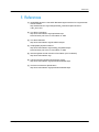
5
References ............................................................................ 29
Rohde & Schwarz Introduction to Attribute Based Instrument Drivers 2
VXIplug&play Instrument Drivers
1 VXIplug&play Instrument Drivers
1.1 Preface
The task of programming instruments in a test system has always been a concern for
end users and a major cost for the overall system development. Many users know that
programming can often be the most time-consuming part of developing a system. The
developer spends much valuable time learning the specific programming requirements
of each instrument in the system. Almost all instruments are designed for interactive
use through a physical front panel and also offer remote control capability via a
communication port on the backside of the instrument. The details for how to program
the instrument remotely are usually documented in the instrument manual in the form
of ASCII command sets that cause the instrument to perform the desired operation.
Documenting an instrument command set in the user manual, along with some
example program listings, has traditionally been the standard method for an instrument
vendor to assist the end user in programming the instrument. These documentation
methods have served the industry well for many years, but this approach still places
the responsibility for writing the program code on the user, many of whom may end up
writing very similar application programs.
If the same command works for multiple instruments, regardless of the manufacturer,
users can interchange or upgrade instruments and reduce the amount of changes to
their application programs. In particular, many of the installed base of users who had
substantial investments in their software environments, that did not easily lend
themselves to software modularity, lobbied for this approach. Through the mid to late
1980s, many standard organizations, including the IEEE, worked on this objective with
little progress. The IEEE 488.2 specification [ANSI/IEEE Std 488.1-1987], completed in
1987, more carefully defined the operation of instruments like the program message
exchange protocol, but did not address the issue of standard command sets.
1
In 1990, the SCPI Consortium [The SCPI Consortium] was formed, which became
part of IVI Foundation in 2002. This organization approved a specification for
standardized commands for message-based programmable instruments. The SCPI
Consortium is not active anymore and the last updated document was published in
1999 [The SCPI Standard]. While more and more companies continue to endorse the
SCPI standard and use it in their new instrument designs, still instruments available
today do not use this standard command set. In addition, while many users of SCPI
instruments appreciated the progress and have experienced improvement in
productivity once they learn the standard command set, instrument interchangeability
is still not a reality because most instruments have different, often unique functionality
and therefore a command set different to the SCPI standard command set. Moreover
syntactically equal SCPI commands are a necessary, but not a sufficient condition for
instrument interchangeability.
While the SCPI standard is certainly recognized by the entire industry as a step
forward, the lack of progress on this issue encouraged both users and vendors to
explore other approaches before SCPI was completed.
1
1MA170_3e
Standard Commands for Programmable Instruments
Rohde & Schwarz Introduction to Attribute Based Instrument Drivers 3
VXIplug&play Instrument Drivers
They needed to decrease the time required to program instruments, facilitating
instrument interchangeability and easing system maintenance. Rather than trying to
solve the problems by standardizing the instruments from all suppliers, both users and
vendors began to take advantage of new computer science technology to address the
issues by making software more modular and flexible.
1.2 The Definition of Instrument Drivers
An instrument driver, in the simplest definition, is a set of software routines that
handles the programmatic details of controlling and communicating with a specific
instrument. The most successful instrument driver concepts have always distributed
instrument drivers in source code and provided end users with access to the same
tools developers use to write drivers. With this philosophy, new instrument drivers were
often easily developed by end users through modifying an existing driver for another
instrument. End users, in general, had come to view the availability of an instrument
driver as an important factor in the choice of a particular instrument. However, users
still had access to standard instrument driver development tools and source codes for
other instruments.
VXIplug&play instrument drivers are defined by VXIplug&play Systems Alliance
[VXIplug&play Systems Alliance], which is part of the IVI (Interchangeable Virtual
Instrument) Foundation [Interchangeable Virtual Instrument Foundation] since 2002.
These drivers offer a simple API (application programming interface) using non
structured data types. This API is defined by a so called “function panel file” which
contains graphical panels. Each of these panels is representing a function's prototype.
Functions are designed to group several instrument's parameters which are logically
tied one to each other. It allows the driver's user to make instrument setup or
measurement in less steps compared to sending SCPI commands using low-level or
VISA functions [Virtual Instrument Software Architecture]. On the other hand, there are
cases where access to specific commands is needed.
Modern instruments capable of measuring, generating and analyzing advanced
2
3
signals, such as WiMAX or LTE , are very complex and sometimes it may be
necessary to configure only a single parameter of the instrument, usually because of
speed (either speed of software execution or speed of instrument's internal
reconfiguration and measurement). Formerly this contradiction was solved by sending
SCPI commands directly using either VISA low level functions like the VISA
Read/Write, or utilizing the function of the driver that is configuring this parameter.
However, issues like instrument state synchronization or error checking needs to be
solved by the user. To avoid mixing two different programming techniques new drivers
have been designed with layered API consisting of low level and high level functions.
Low level functions are usually using only one SCPI command. High level functions are
then calling into several low level functions according to its parameters. While this API
structure allows the user to benefit from both having well organized high level functions
and having low level functions, it leads to high number of exported functions (and VIs
4
in case of LabVIEW instrument drivers).
Rohde & Schwarz offers a new approach to balance the instrument driver's API called
Attribute Based Instrument Drivers.
2
For details on WiMAX please visit http://www.rohdeschwarz.com/appnote/1MA96.html
3
For details on LTE please visit http://www.rohde-schwarz.com/appnote/1MA111.html
4
For details on National Instrument LabVIEW please visit http://www.ni.com/labview/
1MA170_3e
Rohde & Schwarz Introduction to Attribute Based Instrument Drivers 4
Attribute Based Instrument Drivers
2 Attribute Based Instrument Drivers
An attribute can be defined as an element of a hardware configuration of an instrument
or a software configuration of an instrument driver. Thus each instrument setting is
associated with a hardware configuration attribute.
In general an attribute based driver is a standard VXIplug&play instrument driver. It can
be used as a traditional single layer instrument driver. However, if the user needs to
configure or measure a single parameter which is part of complex high level function.
He does not have to directly use a SCPI command or if available, a low level function,
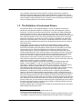
but can use the appropriate attribute access function. For instance the high level
5
function of the Rohde & Schwarz spectrum analyzer instrument driver (rsspecan ) for
configuring the sweep coupling sets three parameters: the resolution- and the video
bandwidth, as well as the sweep time. So for example to configure only the resolution
bandwidth, the corresponding attribute can be used (illustrated in the figure below step
a) and step aa)).
Attribute based drivers are leveraging the best from both VXIplug&play instrument
drivers and IVI-C instrument drivers. Low level functionality is implemented in the same
way as in IVI-C drivers via attributes. The high level driver functions are similar to the
IVI standard, but not limited to the restrictions of the IVI class definition, like strict
definition of function names, number of arguments and its names of functions which
are following the IVI class specification.
Most high level functions are implemented using attributes as well. In this case also the
shown steps a) and aa) are executed when calling one of theses high level functions.
However, not all instrument commands can be implemented as attributes, thus some
functions are not using attributes, but are implemented in the traditional way, as
already mentioned above. In that case the shown step b) is executed. For instance all
functions, which have arrays as part of their API, fall into this category, for example a
recorded trace of a spectrum.
Figure 1: Architecture of Rohde & Schwarz attribute based instrument drivers: Example of
instrument hardware configuration setting, e.g. a)-aa) frequency setting or b) reading trace data
5
1MA170_3e
The rsspecan instrument driver is available at http://www.rohde-schwarz.com/drivers.
Rohde & Schwarz Introduction to Attribute Based Instrument Drivers 5
Attribute Based Instrument Drivers
2.1 Attribute Access Functions
When a high level function in an instrument driver queries or modifies the current
setting of an attribute, it does so by calling one of the Rs_GetAttribute or
6
Rs_SetAttribute functions. Each driver contains five prefix _GetAttribute functions and
five prefix_SetAttribute functions, one for each possible attribute data type. These are
called typesafe functions.
7
Each driver also exports five typesafe prefix_CheckAttribute functions. Instrument
drivers can call these functions to verify that a particular value is valid for an attribute.
This allows users to bypass the high level functions in instrument drivers and directly
query and modify the values of instrument attributes. The prefix_GetAttribute,
prefix_SetAttribute, and prefix_CheckAttribute functions are merely wrappers around
calls to the Rs_GetAttribute, Rs_SetAttribute, and Rs_CheckAttribute functions.
This instrument driver contains high-level functions that set most of the instrument
attributes. It is best to use the high-level driver functions as much as possible, because
they handle order dependencies.
2.2 Attributes and its Data Types
Attributes can be grouped into two categories – hardware configuration attributes and
software control attributes. Generally, each instrument setting is associated with a
hardware configuration attribute, e.g. a frequency setting. Hardware configuration
attributes allow the user to set and query values of the associated instrument settings.
Software control attributes control how the instrument driver works rather than
representing particular instrument settings. Those allow users to enable and disable
features such as range checking and instrument status checking. For more information
about that, please refer to chapter 3.4.
6
prefix stands for a corresponding attribute based instrument driver, e.g.
prefix_SetAttributeBoolean(…) stands for rsspecan_SetAttributeBoolean(…) in case of
the rsspecan attribute based instrument driver.
7
Five type safe functions are available for following data types: ViBoolean,
ViInt32, ViReal64, ViString and ViSession.
1MA170_3e
Rohde & Schwarz Introduction to Attribute Based Instrument Drivers 6
Attribute Based Instrument Drivers
Attributes are used in conjunction with the following data types:
ViBoolean
ViInt32
ViReal64
ViString
ViSession
SCPI commands with enumerated string argument, e.g.
[SENSe<1|2>:]AVERage:TYPE VIDeo | LINear …) are realized by an attribute
of data type ViInt32 and proper range table (see image below). The SCPI command
itself is implemented in the attribute data structure which is encapsulated by the
instrument driver.
For instance a SCPI command with more than one argument can’t be implemented as
attributes, but instead are implemented as high level functions. The same is also true
for SCPI commands which are dealing with data sets. In the Rohde & Schwarz
spectrum analyzer for example, the function for reading a Y-trace of a spectrum
analyzer is implemented in that way.
2.2.1 Implementation of Attributes in C
Attributes are implemented as global data structures defined in file 'prefix_attributes.c'.
Because all drivers are distributed in source code, users can freely modify, remove or
add any attribute, range table and repeated capabilities. Data structures are interpreted
by the core, which is implemented in files ‘rsidr_core.c’ and ‘rsidr_core.h’. These two
files are always the same for all Rohde & Schwarz attribute drivers, thus when
combining source codes of two different drivers these two files need to be added to the
8
project once. Using attributes in the C-based LabWindows/CVI environment is
described in chapter 3.2.
2.2.2 Implementation of Attributes in LabVIEW
Similarly to C implementation, in the latest version attributes and range tables in
LabVIEW are implemented as global structures, which are accessed via global
variables. Search for attributes and range tables uses pre-generated sorted hash
tables and binary search instead of linear search. A global variable containing attribute
definition is unique for each instrument driver as well as the driver core, which is
distributed as LabVIEW library. This is the same for all Rohde & Schwarz attributebased LabVIEW drivers. As speaking of attribute based driver which are shipped as
project based LabVIEW code, here the same implementation of the functional global
variable is realized, the only difference are different file names of the related files.
Using attributes in LabVIEW is described in chapter 3.1.
8
For details on National Instrument LabWindows/CVI please visit
http://www.ni.com/lwcvi/
1MA170_3e
Rohde & Schwarz Introduction to Attribute Based Instrument Drivers 7
Attribute Based Instrument Drivers
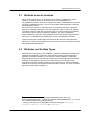
2.3 Range Table
An Attribute can have its range table which defines the attribute's valid values. There
are three types of range tables:
● Ranged - valid values are defined as a closed interval of integer or floating point
values (according to the range table's data type). The number of marker available
on a spectrum analyzer can be named as example.
● Coerced - valid values are defined as a discrete set of numbers. If this range table
is associated with an attribute, then the attribute values are coerced to the nearest
value listed in the coerced range table. For example the number of sweep points of
a spectrum can be limited to an increment of 100 for number of points equal or
greater than 201.
● Discrete - valid values are defined as a discrete set of numbers. No coercion
applies. This range table is also used for mapping of integer constant values to
enumerated string command arguments. For instance the string ‘VIDeo’, which
needs to be sent to the instrument can be mapped to the symbolic constant
PREFIX_VAL_AVERAGE_TYPE_VIDEO with integer value (0 for instance).
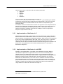
2.4 Repeated Capabilities
Many instruments contain multiple instances of the same type of functionality. For
example, many instruments have multiple channels, windows or traces with
independent settings. The general term for functionality that is duplicated in an
instrument is repeated capability. Repeated capabilities can be complex. An instrument
may have multiple sets of repeated capabilities, such as windows and traces, or
markers. Also, repeated capabilities may be nested within other repeated capabilities,
for example traces within displays.
Repeated capability instances are specified by a string parameter to each function that
accesses the repeated capability or by a function that selects the active instance.
Attribute access functions are provided with a string parameter which selects the
capability to be used by function. To define the usage of a particular capability fill the
string with a proper value. To use more than one repeated capability in one attribute,
separate them with comma.
The attribute access functions include a repeated capability selector parameter for use
with channel-based attributes or attributes of repeated capabilities. When using
attribute access functions on attributes (see chapter 2.1) that do not apply to repeated
capabilities, application programs pass VI_NULL or an empty string for the parameter.
Dynamic Repeated Capabilities
®
Some instruments, for instance R&S ZNB, require user to create own identification
strings for repeated capabilities (traces, channel, windows, etc.). In this case the
multiplicity and the formatting of the so called dynamic repeated capabilities is defined
by the user in the run time. In general this implies that the user must allow the driver to
track the creation and the deletion of such repeated capabilities.
Even dynamic repeated capabilities are statically predefined with default values, which
can be found on the instrument after its reset. For instance there’s always after reset
one trace, one window and one channel defined in network vector analyzer. These
capabilities are statically predefined in instrument driver. However, these can be
deleted or replaced afterwards during run time of the software.
Examples for this topic are presented in chapter 3.1.1, chapter 3.2.1 and chapter 3.3.1.
1MA170_3e
Rohde & Schwarz Introduction to Attribute Based Instrument Drivers 8
Attribute Based Instrument Drivers
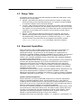
2.5 Multithread Safety
Rohde & Schwarz attribute drivers are multithread safe. Multithread safety means that
multiple threads in the same process can use the same driver session and that
different sessions of the same driver can run simultaneously on different threads.
To access a driver session from multiple threads, the application initializes the driver in
one thread and then shares the session handle or object with other threads. If an
application wants to treat several calls to a driver as a single operation that other
threads must not interfere with, the application must block other threads during the
sequence of calls. The application can do this by using synchronization functions
provided by the operating system or programming environment. Locking inside of a
driver has not yet been implemented.
Multithread safety does not provide any mechanism to allow multiple processes to
share the same session. It also does not provide any mechanism to synchronize
between multiple threads or processes that open multiple sessions on the same
physical instrument. To synchronize access to the same physical instrument from
multiple processes, applications must use its own resource locking.
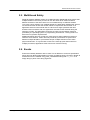
2.6 Events
Events are basically attributes with no data. This is different to IVI driver specification
which does not allow implementation of events via attribute engine. Events in Rohde &
Schwarz drivers are realized using prefix_SetAttributeViString with VI_NULL or an
empty string in place of the string argument.
1MA170_3e
Rohde & Schwarz Introduction to Attribute Based Instrument Drivers 9
Use of Rohde & Schwarz Attribute Instrument Drivers
3 Use of Rohde & Schwarz Attribute
Instrument Drivers
The following example is referring to the rsspecan and the rsvna instrument driver. The
described procedures are all adaptable to other attribute based Rohde & Schwarz
instrument drivers, only the naming of the files can be different. The naming convention
is PREFIX, where the PREFIX is the abbreviation of a specific instrument
driver.
3.1 How to Use Attributes in LabVIEW
This section explains how to use the attributes in the rsspecan instrument driver. This
is necessary, for instance, if the driver does not support the functionality via high level
VIs.
Please also use the Driver Attribute Help chm file. This help file is accessible via the
Instrument Driver Help file (e.g. rsspecan.chm).
Example: How to set the Frequency Start value by attributes
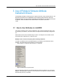
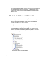
To select an attribute use the provided Express VI included in the instrument driver
package. This instrument driver Express VI can be found in:
User Libraries => Express User Libraries => rsspecan
Figure 2: Palette menu of rsspecan driver.
Drag and drop the rsspecan Core Attribute Express Source.vi/Source.vi in your block
diagram. After placing the express VI, the front panel of the Express VI will be opened
automatically (see Fig. unterhalb).
1MA170_3e
Rohde & Schwarz Introduction to Attribute Based Instrument Drivers 10
Use of Rohde & Schwarz Attribute Instrument Drivers
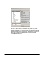
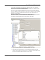
Figure 3: Front panel of rsspecan_core_attribute_express Source.vi.
Now select an attribute from the tree structured list. Each attribute has a different
access type (read only, write only or read/write). The proper read/write operation can
be selected in the Attribute Operation box at the bottom left corner.
Repeated capabilities are set by using a string control at the bottom of the panel called
Repeated Capabilities (e.g. TR1 referring to trace 1, Win0 referring to screen A). The
attribute value is entered using standard LabVIEW controls for each data type
(numeric, Boolean, string or ring).
For example, in Basic Operation use the Set Frequency Start value:
1MA170_3e
Rohde & Schwarz Introduction to Attribute Based Instrument Drivers 11
Use of Rohde & Schwarz Attribute Instrument Drivers
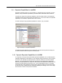
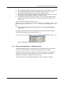
Figure 4: Configuring "Set Frequency Start" example.
1. Select the proper attribute. To find the designated attribute easily the
rsspecan.chm help file can be used to look for it. Be aware of the fact that the tree
structures in the help file and the Express VI are the same.
2. Fill the Repeated Capabilities box accordingly.
3. Type the desired frequency value in the Value text box.
4. After clicking the OK button, a new instance of an attributed-based VI is generated.
The name of the VI and its predefined values and also the help file will be adapted.
The result of the procedure is shown in Fig. unterhalb:
Figure 5: Instanced attribute-based VI "Set Frequency Start".
1MA170_3e
Rohde & Schwarz Introduction to Attribute Based Instrument Drivers 12
Use of Rohde & Schwarz Attribute Instrument Drivers
3.1.1 Repeated Capabilities in LabVIEW
Repeated capability instances are specified by a predefined string parameter for each
property. They can also be specified by a function which selects the active instance.
To define the usage of a particular capability, enter the proper value in the Repeated
Capability text box in the front panel of the Express VI. To use more than one repeated
capability in one attribute, separate them with a comma.
A marker example using repeated capabilities is shown in Fig. unterhalb:
Figure 6: Example of "Repeated Capabilities".
The attribute and its features can be changed at any time later by double-clicking the
VI, which recalls the shown Express VIs front panel.
3.1.2 Dynamic Repeated Capabilities in LabVIEW
In comparison to the previously described repeated capabilities, the so called dynamic
repeated capabilities are specified by a user defined string parameter for each property
in run time. For example, a property can be a channel or a trace of a vector network
analyzer. The instrument driver stores and tracks this user defined string parameter
each time a new parameter is created. For this reason it is important to create new one
using the provided high level functions (e.g. “Trace Add Diagram Area.vi”). Creating
new parameters using attribute access functions would not allow the instrument driver
to trace this newly created dynamic repeated capability accordingly. How to use a high
level function is shown in the picture unterhalb.
1MA170_3e
Rohde & Schwarz Introduction to Attribute Based Instrument Drivers 13
Use of Rohde & Schwarz Attribute Instrument Drivers
Figure 7: Example how to create a dynamic repeated capability using a high level function
This example outlines how to use dynamic repeated capabilities, here MyTrace2, in
combination with high level function as well as using it with Express VI. Furthermore
the default channel setup of the Rohde & Schwarz ZNB network analyzer is required.
For the following example the dynamic repeated capability is fed into the Express VI
via parameter. The internal default value Channel1 will be used as channel
configuration. Here the parameter MyTrace2 serves as input value for the pictured
Express VI. The picture unterhalb also shows the attribute access Express VI’s user
interface:
Figure 8: Example how to use a dynamic repeated capability using the attribute-access
ExpressVI
1MA170_3e
Rohde & Schwarz Introduction to Attribute Based Instrument Drivers 14
Use of Rohde & Schwarz Attribute Instrument Drivers
After running this sequence a new channel and trace has been added on the
instrument and is stored in the instrument driver for future use. To access this new
trace the dynamic repeated capability “MyTrace2” has to be used. In this case the new
trace can be addressed by other high level functions, as well as using the attributeaccess functions directly. The showed sequence is deleting the repeated capability
“MyTrace2” again.
3.2 How to Use Attributes in LabWindows/CVI
This section explains how to use attributes in the rsspecan instrument driver. This is
necessary, for instance, if the driver does not support the functionality via high level
functions (API).
Please use the Driver Attribute Help chm file. This help file is accessible via the
Instrument Driver Help file (e.g. rsspecan_vxi.chm).
The rsspecan.sub file has to be added to the project. This file is mandatory for
browsing attributes.
Example: How to set the Frequency Start value by attributes
To select an attribute, use the provided function panels, which are included in the
instrument driver package. These instrument driver function panels can be found in:
Instruments=>ROHDE & SCHWARZ SpecAn=>Configuration=>Set/Get/Check
Attribute/Repeated Capabilities
Figure 9: Function panel for rsspecan driver attributes.
1MA170_3e
Rohde & Schwarz Introduction to Attribute Based Instrument Drivers 15
Use of Rohde & Schwarz Attribute Instrument Drivers
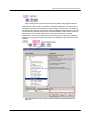
To open the function panel, double-click on the desired function. Fig. 9 shows the
function panel of "rsspecan_SetAttributeViReal64". Clicking on the "Attribute ID" text
box opens the "Select Attribute Constant" window.
Now you can select the desired attribute from the tree structured list. Each attribute
can have a different access type (read only, write only or read/write). Proper read/write
operation can be selected by the proper function panel, either Set Attribute, Get
Attribute or Check Attribute.
Repeated capabilities are set by using identifier or identifier names within the function
panel called rsspecan_GetAttributeRepeatedCapabilityId[s|Names].
For example, in Basic Operation use the Set Frequency Start value:
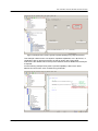
Figure 10: Selecting an attribute in the "SetAttributeViReal64" function panel.
1. Please select the desired attribute. To find the designated attribute easily the
rsspecan.chm help file can be used to look for it. Be aware of the fact that the tree
structures in the help file and the Express VI are the same.
1MA170_3e
Rohde & Schwarz Introduction to Attribute Based Instrument Drivers 16
Use of Rohde & Schwarz Attribute Instrument Drivers
Fill the Repeated Capabilities text box according to the documentation, e.g. “Win0”.
Type the desired frequency value in the Attribute Value text box, e.g. "1e+9".
Enter a valid instrument handle in the Instrument Handle text box.
It is strongly recommended to evaluate the return value of your function, if you type
the name of a declared integer variable in the Status text box.
6. To include the function into your source code, you can copy the created function
string out of the window on the button of the function panel and insert it into the
source code.
2.
3.
4.
5.
The result of this procedure is shown in Fig. 10.
Figure 11: Building a function string on the button of the "rsspecan_SetAttributeViReal64"
function panel.
The attribute and its features can be changed at any time later by right-clicking the
function and recalling the function panel. See Fig. 11:
Figure 12: Recalling the function panel to modify the attributes.
3.2.1 Repeated Capabilities in LabWindows/CVI
Repeated capability instances are specified by a string parameter for each property.
They can also be specified by a function which selects the active instance.
To define the usage of particular capability, enter the proper value in the Repeated
Capability text box in the function panel. If more than one repeated capability is
required for one attribute, separate them with a comma.
A marker example using repeated capabilities is shown in the figure unterhalb:
1MA170_3e
Rohde & Schwarz Introduction to Attribute Based Instrument Drivers 17
Use of Rohde & Schwarz Attribute Instrument Drivers
Figure 13: Example of "Repeated Capabilities" in LabWindows/CV.
The attribute and its features can be changed at any time later by recalling the function
panel, which recalls the shown panel.
3.2.2 Dynamic Repeated Capabilities in LabWindows/CVI
In comparison to the previously described repeated capabilities, the so called dynamic
repeated capabilities are specified by a user defined string parameter for each property
in run time. For example, a property can be a channel or a trace of vector network
analyzer. The instrument driver stores and tracks this user defined string parameter
each time a new parameter is created. For this reason it is important to create new
using the provided high level functions (e.g. “rsvna_TraceAddDiagramArea(…)”).
Creating new parameters using attribute access functions would not allow the
instrument driver to trace this newly created dynamic repeated capability accordingly.
How to use a high level function is shown in the picture below.
1MA170_3e
Rohde & Schwarz Introduction to Attribute Based Instrument Drivers 18
Use of Rohde & Schwarz Attribute Instrument Drivers
Figure 14: Example how to create a dynamic repeated capability using a high level function
This example outlines how to use dynamic repeated capabilities, here “MyTrace2”, in
combination with an high level function as well as using it with a front panel.
Furthermore the default channel setup of the Rohde & Schwarz ZNB network analyzer
is required.
For the following example the dynamic repeated capability is fed into the driver
attribute access function via a constant string parameter.
1MA170_3e
Rohde & Schwarz Introduction to Attribute Based Instrument Drivers 19
Use of Rohde & Schwarz Attribute Instrument Drivers
Figure 15: Example how to use a dynamic repeated capability using the attribute-access
functions
After running this sequence a new channel and trace has been added on the
instrument and is stored in the instrument driver for future use. To access this new
trace the dynamic repeated capability “MyTrace2” has to be used. In this case the new
trace can be addressed by other high level functions, as well as using the attributeaccess functions directly. This attribute-access function is deleting the trace. The
showed sequence is deleting the repeated capability “MyTrace2” again.
3.3 How to Use Attributes in Microsoft Visual Studio
Using C#
This section explains how to use attributes in the rsspecan instrument driver in
Microsoft Visual Studio 2008. This is necessary, for instance, if the driver does not
support the functionality via high level functions (API).
In the following examples the programming language C# is used.
9
The rsspecan.cs (or the rsspecan64.cs ) file has to be added to the project. This file
comes together with the VXIplug&play driver and is a prerequisite for using the driver
in C#.
To control an instrument via an attribute, use one of the provided get and set functions
of the C# wrapper. The available functions can be found in the following list:
●
●
●
●
●
●
●
●
●
●
SetInt32
GetInt32
SetDouble
GetDouble
SetBoolean
GetBoolean
SetString
GetString
SetSession
GetSession
(rsspecan_SetAttributeViInt32)
(rsspecan_GetAttributeViInt32)
(rsspecan_SetAttributeViReal64)
(rsspecan_GetAttributeViReal64)
(rsspecan_SetAttributeViBoolean)
(rsspecan_GetAttributeViBoolean)
(rsspecan_SetAttributeViString)
(rsspecan_SetAttributeViString)
(rsspecan_SetAttributeViSession)
(rsspecan_GetAttributeViSession)
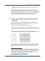
The respective functions and their documentation can be found in the Instrument
Driver Help file in Instrument Driver Tree Structure=>Configuration=>Set/Get/Check
Attribute/Repeated Capabilities referring to listed function names in the brackets
above.
9
It is important to distinguish between 32-bit and 64-bit remote control software
applications. These files are wrapper files for bitness dependent dynamically loaded
libraries. Please always configure your Microsoft Visual Studio project to be 32-bit or
64-bit as target. The default setup “Any CPU” must not be enabled. For further
information please refer to Application Note 1MA153, available on
http://www.rohde-schwarz.com/appnote/1MA153.
1MA170_3e
Rohde & Schwarz Introduction to Attribute Based Instrument Drivers 20
Use of Rohde & Schwarz Attribute Instrument Drivers
Example: How to set the Center Frequency value by attributes
This example shows how to use attributes without repeated capabilities. The use of
repeated capabilities is described in section 3.3.1.
To find the proper attributes for specific configurations, the rsspecan_vxi.chm help file
can be used. All available attributes are listed in the Instrument Driver Help chapter
under Driver Attribute Help; see figure unterhalb.
Figure 16: Documentation of available attributes in the rsspecan instrument driver.
C# attributes are accessible through the enum rsspecanProperties which is
defined in the namespace InstrumentDrivers of the wrapper file rsspecan.cs.
For example, in Basic Operation use the Center Frequency attribute
rsspecanProperties.FrequencyCenter (called
RSSPECAN_ATTR_FREQUENCY_CENTER in the VXIplug&play chm help file) for
configuring the center frequency as shown in the listing below:
using InstrumentDrivers;
namespace rsspecan_Application_Example
{
class Program
{
static void Main(string[] args)
{
string resourceName = "TCPIP::FSP7-100894::INSTR";
bool idQuery = true;
bool resetDevice = true;
//Open driver session
rsspecan m_specAn = new rsspecan(resourceName, idQuery,
resetDevice);
1MA170_3e
Rohde & Schwarz Introduction to Attribute Based Instrument Drivers 21
Use of Rohde & Schwarz Attribute Instrument Drivers
//center frequency 1GHz
double centerFrequency = 1e9;
m_specAn.SetDouble(rsspecanProperties.FrequencyCenter,
centerFrequency);
//...insert more configuration and measurements here
//Close driver session
m_specAn.Dispose();
m_specAn = null;
}
}
}
3.3.1 Repeated Capabilities in C#
Repeated capability instances are specified by a string parameter for each property.
They can also be specified by a function which selects the active instance.
To define the usage of particular capability, the following overloaded functions are
provided by the C# wrapper file, for example the rsspecan.cs:
●
●
●
●
●
●
●
●
SetInt32
GetInt32
SetDouble
GetDouble
SetBoolean
GetBoolean
SetString
GetString
(rsspecan_SetAttributeViInt32)
(rsspecan_GetAttributeViInt32)
(rsspecan_SetAttributeViReal64)
(rsspecan_GetAttributeViReal64)
(rsspecan_SetAttributeViBoolean)
(rsspecan_GetAttributeViBoolean)
(rsspecan_SetAttributeViString)
(rsspecan_SetAttributeViString)
A marker example using repeated capabilities is shown in the following example:
//repeated capabilty example
//set a marker to a specfic frequency
double freqPosition = 1.5e9;
m_specAn.SetDouble(rsspecanProperties.MarkerPosition, "Win0,M1", freqPosition);
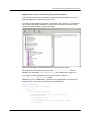
The following figure outlines the “Supported Repeated Capabilities” of the attribute
rsspecanProperties.MarkerPosition (called RSSPECAN_ATTR_MARKER_POSITION
in the rsspecan.chm help file).
1MA170_3e
Rohde & Schwarz Introduction to Attribute Based Instrument Drivers 22
Use of Rohde & Schwarz Attribute Instrument Drivers
Figure 17: Marker example to explain repeated capabilities.
3.3.2 Dynamic Repeated Capabilities in C#
In comparison to previously described repeated capabilities, the so called dynamic
repeated capabilities are specified by a user defined string parameter for each property
in run time. For example, a property can be a channel, a trace or a window of vector
network analyzer. The instrument driver stores and tracks this user defined string
parameter each time a new parameter is created. For this reason it is important to
create new using the provided high level functions (e.g.
“m_specAn.TraceAddDiagramArea(…)“). Creating new parameters using attribute access
functions would not allow the instrument driver to trace this newly created dynamic
repeated capability accordingly. How to use a high level function is shown below.
/* add a new trace “MyTrace2” into a new diagramm area */
m_VNA.TraceAddDiagramArea(winNumber, chanNumber, "MyTrace2");
This example outlines how to use dynamic repeated capabilities, here “MyTrace2”, in
combination with high level function. To get this line of code executed, the default
channel setup of the Rohde & Schwarz ZNB network analyzer is required.
For the following example the dynamic repeated capability is fed into the driver
attribute access function via a string parameter.
/* delete the trace named "MyTrace2" */
m_VNA.SetString(rsvnaProperties.TraceDelete, "Channel1" /*default*/, "MyTrace2");
1MA170_3e
Rohde & Schwarz Introduction to Attribute Based Instrument Drivers 23
Use of Rohde & Schwarz Attribute Instrument Drivers
After running this code a new channel and trace has been added on the instrument
and is stored in the instrument driver for future use. To access this new trace the
dynamic repeated capability “MyTrace2” has to be used. In this case the new trace can
be addressed by other high level functions, as well as using the attribute-access
functions directly. This attribute-access function is deleting the trace. The showed
sequence is deleting the repeated capability “MyTrace2” again.
3.4 Tips and Tricks
3.4.1 Execution Speed: Disable Instrument Status Checking
If instrument status checking is enabled, the driver automatically checks the status of
the instrument after most operations. If the instrument indicates an error condition, the
driver returns a special error code. The user then calls the error query function to
retrieve the instrument specific error code from the instrument.
Instrument status checking is most useful during debugging. Once application
development is complete, this feature can be disabled to maximize performance.
3.4.2 How to Build Executables or Libraries in LabVIEW
The driver core of the attribute-based instrument drivers is dynamically linked to any
executed VI during runtime. This cannot be recognized by the LabVIEW application
builder. The LabVIEW application builder follows all static dependencies and includes
them in the distributed package when building an executable.
To create an executable in LabVIEW, please manually add all VIs in the
<instr.lib>\PREFIX \_utility\callbacks folder to the LabVIEW project. In case of project
based driver please add the Private folder to your project. With this manual reference,
the driver core is included in the build and the driver core is accessible during runtime.
3.4.3 Error Handling: “Instrument version not valid”
If option checking is enabled, the driver checks first, if the following command is
supported by the connected instrument. While the initialization of the driver the “ID
Query” has to be enabled to correctly identify the connected instrument. Based on the
installed instrument options, the driver is generating the error “Instrument version not
valid” if the command is not supported by the instrument.
For extended debugging the option checking functionality can be disabled using the
function/VI “Option Checking” and set the input variable to “False”. This can be found
in the “Utility Functions” folder of the driver documentation
1MA170_3e
Rohde & Schwarz Introduction to Attribute Based Instrument Drivers 24
Use of Rohde & Schwarz Attribute Instrument Drivers
3.4.4 Error Handling: Range Checking
If range checking is enabled, the driver checks if the input parameters are within the
valid range for the connected instrument. Range checking is most useful during
debugging. After users have validated their programs, they can disable range checking
to maximize performance.
Using the function/VI “Option Checking” and set the input variable to “False”. This can
be found in the “Utility Functions” folder of the driver documentation.
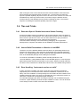
3.4.5 How to Minimize the Size of an Attribute-Based Instrument Driver
The Rohde & Schwarz attribute-based instrument drivers are by definition divided into
different independent modules. These modules are based on the instrument’s
hardware and software options. Consequently, it is possible to include only the
instrument driver core modules and the other driver modules corresponding to the
instrument options used. This allows you to avoid unused driver modules within your
development project.
LabVIEW driver
To avoid unused VIs in a LabVIEW project, you can simply delete unused folders
inside the instr.lib folder. The folders minimally needed for a correctly operating
instrument driver are shown in the following, using the rsspecan LabVIEW instrument
driver as an example.
1MA170_3e
Rohde & Schwarz Introduction to Attribute Based Instrument Drivers 25
Use of Rohde & Schwarz Attribute Instrument Drivers
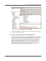
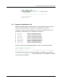
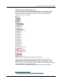
Figure 18: Possible configuration of the rsspecan instrument driver.
In the figure above, the minimal recommended configuration of the rsspecan LabVIEW
instrument driver is highlighted in gray. For example, to have a proper setup for
10
performing measurements on an LTE downlink signal, only the K100- EUTRA LTE
Downlink folder needs to be preserved besides the folders highlighted in gray. The
remaining folders can be easily deleted. The content of the LabVIEW
user.lib\_express\rsspecan folder is mandatory.
This is procedure is also applicable to other attribute-based instrument drivers.
10
1MA170_3e
UMTS Long Term Evolution (LTE) Technology Introduction
Rohde & Schwarz Introduction to Attribute Based Instrument Drivers 26
Use of Rohde & Schwarz Attribute Instrument Drivers
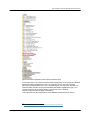
LabWindows/CVI and VXIplug&play driver
For C/C++-based projects, there is also the possibility to easily eliminate unused
source code. The source code files minimally needed for a correctly operating
instrument driver are shown unterhalb, using the rsspecan LabWindows/CVI
instrument driver as an example.
Figure 19: Possible configuration of the rsspecan instrument driver.
In the figure above, the minimal recommended configuration of the rsspecan
LabWindows/CVI instrument driver is highlighted in gray. For example, to have a
11
proper setup for performing measurements on an LTE downlink signal, only the
rsspecan_k100_k102.c file needs to be preserved besides the files highlighted in gray.
The remaining folders can be easily deleted.
This is procedure is also applicable to other attribute-based instrument drivers.
11
1MA170_3e
UMTS Long Term Evolution (LTE) Technology Introduction
Rohde & Schwarz Introduction to Attribute Based Instrument Drivers 27
Related Documents
4 Related Documents
1MA170_3e
Application Note 1MA153: Development Hints and Best Practices for Using
Instrument Drivers http://www.rohde-schwarz.com/appnote/1MA153.html
Automatic Measurement Control, A tutorial on SCPI and IEEE 488.2; John M.
Pieper; Rohde & Schwarz GmbH & Co. KG
IEEE Std 488.2-1992 IEEE Standard Codes, Formats, Protocols, and Common
Commands for Use With IEEE Std 488.1-1987, IEEE Standard Digital Interface for
Programmable Instrumentation
http://standards.ieee.org/reading/ieee/std_public/description/im/488.21992_desc.html
Rohde & Schwarz Introduction to Attribute Based Instrument Drivers 28
References
5 References
[1] ANSI/IEEE Std 488.1-1987 IEEE Standard Digital Interface for Programmable
Instrumentation
http://standards.ieee.org/reading/ieee/std_public/description/im/488.11987_desc.html
[2] The SCPI Consortium
http://www.ivifoundation.org/scpi/default.aspx
Note: Became part of the IVI Foundation in 2002
[3] The SCPI Standard
http://www.ivifoundation.org/docs/SCPI-99.pdf
[4] VXIplug&play Systems Alliance
http://www.ivifoundation.org/VXIPlug_Play/default.aspx
Note: Became part of the IVI Foundation in 2002
[5] Interchangeable Virtual Instrument Foundation (IVI Foundation)
http://www.ivifoundation.org/
[6] Virtual Instrument Software Architecture (VISA)
http://www.ivifoundation.org/specifications/default.aspx
[7] IVI Driver Architecture Specification
http://www.ivifoundation.org/specifications/default.aspx
1MA170_3e
Rohde & Schwarz Introduction to Attribute Based Instrument Drivers 29
About Rohde & Schwarz
Rohde & Schwarz is an independent group
of companies specializing in electronics. It is
a leading supplier of solutions in the fields of
test and measurement, broadcasting,
radiomonitoring and radiolocation, as well as
secure communications. Established more
than 75 years ago, Rohde & Schwarz has a
global presence and a dedicated service
network in over 70 countries. Company
headquarters are in Munich, Germany.
Environmental commitment
● Energy-efficient products
● Continuous improvement in
environmental sustainability
● ISO 14001-certified environmental
management system
Regional contact
Europe, Africa, Middle East
+49 89 4129 12345
[email protected]
North America
1-888-TEST-RSA (1-888-837-8772)
[email protected]
Latin America
+1-410-910-7988
[email protected]
Asia/Pacific
+65 65 13 04 88
[email protected]
China
+86-800-810-8228 /+86-400-650-5896
[email protected]
This application note and the supplied
programs may only be used subject to the
conditions of use set forth in the download
area of the Rohde & Schwarz website.
R&S® is a registered trademark of Rohde & Schwarz
GmbH & Co. KG; Trade names are trademarks of the
owners.
Rohde & Schwarz GmbH & Co. KG
Mühldorfstraße 15 | D - 81671 München
Phone + 49 89 4129 - 0 | Fax + 49 89 4129 – 13777
www.rohde-schwarz.com