1
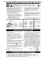
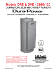
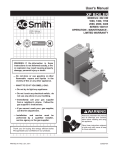
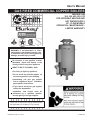
User's Manual GAS FIRED COMMERCIAL COPPER BOILERS MODELS: HW 300, 399, 420, 520, 670 FOR HYDRONIC HEATING AND HOT WATER SUPPLY UP - FLOW MODELS OPERATION - MAINTENANCE LIMITED WARRANTY 25589, Highway 1 McBee, SC 29101 H WARNING: If the information in these instructions is not followed exactly, a fire or explosion may result causing property damage, personal injury or death. Do not store or use gasoline or other flammable vapors and liquids in the vicinity of this or any other appliance. WHAT TO DO IF YOU SMELL GAS: • Do not try to light any appliance. • Do not touch any electrical switch; do not use any phone in your building. • Immediately call your gas supplier from a neighbor’s phone. Follow the gas supplier’s instructions. • If you cannot reach your gas supplier, call the fire department. Installation and service must be performed by a qualified installer, service agency or the gas supplier. Thank you for buying this energy efficient boiler. We appreciate your confidence in our products. PRINTED IN THE U.S.A. 0212 321082-000 TABLE OF CONTENTS TABLE OF CONTENTS�������������������������������������������������������������������������� 2 SAFE INSTALLATION, USE AND SERVICE����������������������������������������� 3 GENERAL SAFETY������������������������������������������������������������������������������� 4 INTRODUCTION������������������������������������������������������������������������������������ 5 Abbreviations used���������������������������������������������������������������������������� 5 Qualifications������������������������������������������������������������������������������������� 5 CONTROL COMPONENTS������������������������������������������������������������������� 6 BOILER START UP AND OPERATIONS��������������������������������������������� 10 Filling the system����������������������������������������������������������������������������� 10 Precautions�������������������������������������������������������������������������������������� 10 Pilot and main burner���������������������������������������������������������������������� 10 Checking and adjusting input���������������������������������������������������������� 12 TROUBLESHOOTING������������������������������������������������������������������������� 16 MAINTENANCE PROCEDURES��������������������������������������������������������� 24 Manual reset high limit switch continuity test����������������������������������� 24 Pressure relief valve test����������������������������������������������������������������� 24 Cleaning and flushing instructions��������������������������������������������������� 24 Venting maintenance����������������������������������������������������������������������� 25 NOTES������������������������������������������������������������������������������������������������� 26 LIMITED WARRANTY�������������������������������������������������������������������������� 27 2 SAFE INSTALLATION, USE AND SERVICE The proper installation, use and servicing of this boiler is extremely important to your safety and the safety of others. Many safety-related messages and instructions have been provided in this manual and on your boiler to warn you and others of a potential injury hazard. Read and obey all safety messages and instructions throughout this manual. It is very important that the meaning of each safety message is understood by you and others who install, use, or service this boiler. This is the safety alert symbol. It is used to alert you to potential personal injury hazards. Obey all safety messages that follow this symbol to avoid possible injury or death. DANGER DANGER indicates an imminently hazardous situation which, if not avoided, will result in injury or death. WARNING WARNING indicates a potentially hazardous situation which, if not avoided, could result in injury or death. CAUTION CAUTION indicates a potentially hazardous situation which, if not avoided, could result in minor or moderate injury. CAUTION CAUTION used without the safety alert symbol indicates a potentially hazardous situation which, if not avoided, could result in property damage. All safety messages will generally tell you about the type of hazard, what can happen if you do not follow the safety message, and how to avoid the risk of injury. The California Safe Drinking Water and Toxic Enforcement Act requires the Governor of California to publish a list of substances known to the State of California to cause cancer, birth defects, or other reproductive harm, and requires businesses to warn of potential exposure to such substances. This product contains a chemical known to the State of California to cause cancer, birth defects, or other reproductive harm. This boiler can cause low level exposure to some of the substances listed in the Act. IMPORTANT DEFINITIONS Gas Supplier: The Natural Gas or Propane Utility or service who supplies gas for utilization by the gas burning appliances within this application. The gas supplier typically has responsibility for the inspection and code approval of gas piping up to and including the Natural Gas meter or Propane storage tank of a building. Many gas suppliers also offer service and inspection of appliances within the building. APPROVALS H 3 GENERAL SAFETY 4 INTRODUCTION QUALIFICATIONS This design complies with the current edition of the ANSI Z21.13 low-pressure boiler standard. QUALIFIED INSTALLER OR SERVICE AGENCY Compliance under this standard implies that when the boiler underwent test, the gas manifold and control assembly provided on the boiler met safe lighting and other performance criteria. Installation and service of this boiler requires ability equivalent to that of a Qualified Agency, as defined by ANSI below. In the field involved. Installation skills such as plumbing, air supply, venting, gas supply and electrical supply are required in addition to electrical testing skills when performing service. Detailed installation diagrams are found in this manual. These diagrams will serve to provide the installer a reference for the materials and methods of piping necessary. It is essential that all water, gas piping and wiring be installed as shown on the diagrams. You should thoroughly read and understand this manual before installation and/or operation of this boiler. ANSI Z21.13 - CSA 4.9: “Qualified Agency” - “Any individual, firm, corporation or company that either in person or through a representative is engaged in and is responsible for (a) the installation, testing or replacement of gas piping or (b) the connection, installation, testing, repair or servicing of appliances and equipment; that is experienced in such work; that is familiar with all precautions required; and that has complied with all the requirements of the authority having jurisdiction.” The factory warranty will be void if the boiler(s) have been improperly installed or operated. In addition to these instructions, the boiler(s) shall be installed in accordance with those installation regulations in force in the local area where the installation is to be made. These shall be carefully followed in all cases. Authorities having jurisdiction should be consulted before installations are made. If you are not qualified (as defined by ANSI above) and licensed or certified as required by the authority having jurisdiction to perform a given task do not attempt to perform any of the procedures described in this manual. If you do not understand the instructions given in this manual do not attempt to perform any procedures outlined in this manual. In the absence of local codes, the installation must comply with the current editions, as follows: In the United States: The National Fuel Gas Code, ANSI Z223.1/NFPA 54 and the National Electric Code, NFPA 70. In Canada: Installation Code CAN/CSA B149.1 and Canadian Electrical Code, CSA C22.1. ABBREVIATIONS USED Abbreviations found in this Instruction Manual include : • ANSI - American National Standards Institute • ASME - American Society of Mechanical Engineers • NEC - National Electrical Code • NFPA - National Fire Protection Association • UL - Underwriters Laboratory • CSA - Canadian Standards Association 5 CONTROL COMPONENTS Figure 1. COMPONENT LOCATIONS 6 AUTO RESET HIGH LIMIT THERMAL BALANCER The high limit is a safety device wired in series with the ignition system. Set the high limit control to approximately 100°F above the maximum designed system temperature. If the boiler outlet water temperature should exceed the high limit setting, the main gas control valve will close but the circulating pump will continue to operate. Maximum adjustable setting is 115°C (239°F) cut-out with a 30°C (86°F) to 250°C (482°F) adjustable differential, see Figure 2. Figure 4 shows the internal wiring of the thermal balancer. The device may be tested after disconnecting the four leads from their respective terminals on the unit. 1. Apply a test light to the yellow and red leads. • The lamp should light as the contact in this circuit is normally closed when the resistor is cool. 2. Apply a light to the black and yellow leads. • The lamp should not light as the contact in this circuit is normally open when the resistor is cool. 3. Remove the test light. 4. Apply 120 volts to the white and red leads which power the 1900 ohm resistor. After a warming period the contacts of the thermal balancer should operate. 5. Remove the test light. 6. Apply the test light as described in steps 1 and 2. While the resistor is still warm the lamp indications should be the opposite as described previously. Figure 2. AUTO RESET HIGH LIMIT INTERMITTENT IGNITION CONTROL MODULE The Honeywell S-8600 control module contains the electronic components of the system and also serves as a control wiring system for the controls mounted on the boiler. The control module performs the following functions: 1. Checks for safe-start by sensing for a false flame condition on start-up. 2. Generates a potential of 15,000 volts for spark ignition of the pilot burner. Figure 4. THERMAL BALANCER 3. Opens the pilot valve. MANUAL RESET HIGH LIMIT 4. Discontinues ignition spark when the pilot flame is established. The S-8600 control used on propane gas models provides safety lockout if the pilot fails to ignite within the pilot flame establishing period. The S-8600 control used on natural gas models continues trial for ignition until pilot flame is established. This boiler is equipped with a manual reset high limit switch, located under the small cover on the side of the jacket, see Figure 5. This device provides positive shutdown of the boiler in the event of boiler or system malfunction. Should the surface temperature of the copper tubing heat exchanger reach 250°F (120°C), the high limit switch will activate, the gas control valve will close, the pilot and main burners will be extinguished. If the high limit switch should shut off unit, check the following conditions: 5. After proof of pilot flame, opens then main valve. 6. On a power loss, shuts the boiler down. When power is restored it will begin a new ignition cycle. • No water in boiler. • Restricted water flow through the boiler. • Improper wiring (boiler firing without circulating pump operating). • Pump failure. 7. On a loss of flame, shuts off main gas and starts trial for pilot ignition. Please refer to Troubleshooting section for more information. After correcting failure condition remove the protector switch cover and push the reset button. The high limit switch may be reset after the coil surface cools to 6°F (3.3°C) below the trip setting. Figure 3. S-8600 INTERMITTENT IGNITION CONTROL MODULE (IID) Figure 5. HIGH LIMIT SWITCH 7 PRESSURE RELIEF VALVE If any pressure relief valve is replaced, the replacement valve must comply with the current editions of the ASME Boiler and Pressure Vessel Code, Section IV or CSA B51, as applicable. Select a pressure relief valve with a discharge NOT less than the boiler input, and a pressure rating NOT exceeding the working pressure of any component in the system. An ASME rated pressure relief valve is furnished with the boiler. A fitting for the pressure relief valve is provided in the top of the boiler. Never operate the heating elements without being certain the boiler is filled with water and a properly sized pressure relief valve is installed in the pressure relief valve opening provided. A. O. Smith supplies a 125 psi pressure relief valve for hot water supply systems and 50 psi pressure relief valve for space heating application. An ASME rated temperature and pressure relief valve must be installed on each and every water storage tank in a hot water supply system. The pressure rating of the pressure relief valve should be equal to or less than the rated pressure capacity of any component in the system including the boiler. Should the valve need to be replaced, call the toll free phone number listed on the back of this manual for further technical assistance. The storage tank temperature and pressure (T & P) relief valve must comply with the applicable construction provisions of the Standard for Relief valves and Automatic Gas Shutoff Devices for Hot Water Supply Systems, Z21.22 - CSA 4.4. The T & P valve must be of the automatic reset type and not embody a single-use type of fusible plug, cartridge or linkage. Explosion Hazard Pressure Relief Valve must comply with ASME code. The T & P relief valve should have a maximum temperature rating of 100°C (210°F), a pressure rating NOT exceeding the lowest rated working pressure of any system component, and a discharge capacity exceeding the total input of the water boilers supplying water to the storage tank. Properly sized Pressure Relief Valve must be installed in opening provided. Can result in overheating and excessive tank pressure. Locate the T & P relief valve (a) in the top of the storage tank or (b) in the side of the tank on centerline within upper 6 inches from the top of the tank. Refer to the Piping Diagrams section in Instruction Manual. Tapping shall be threaded in accordance with the latest version of the Standard for Pipe Threads, General Purpose (inch), ANSI/ASME B.120.1. Can cause serious injury or death. A discharge pipe from the pressure relief valve should terminate at an adequate floor drain. Do not thread, plug, or cap the end of the drain line. CAUTION Water Damage Hazard • Pressure Relief Valve discharge pipe must terminate at adequate drain. The Discharge Pipe: • Shall not be smaller in size than the outlet pipe size of the valve, or have any reducing couplings or other restrictions. • Shall not be plugged or blocked. • Shall not be exposed to freezing temperatures. • Shall be of material listed for hot water distribution. • Shall be installed so as to allow complete drainage of both the pressure relief valve and the discharge pipe. • Must terminate a maximum of six inches above a floor drain or external to the building. In cold climates, it is recommended that the discharge pipe be terminated at an adequate drain inside the building. • Shall not have any valve or other obstruction between the pressure relief valve and the drain. Once the boiler is installed and filled with water and the system is pressurized, manually test the operation of the pressure relief valve. 8 Use anti-scald valve(s) in the hot water system to reduce the risks of scalds at points of use such as lavatories, sinks and bathing facilities. TANK TEMPERATURE CONTROL The water temperature in the storage tank is controlled by the Tank Temperature Control. The sensing element is mounted inside the hot water storage tank. A change in water temperature in the storage tank lower than the Tank Temperature Control setting will cause the sensor to close its contacts and consequently energize the boiler. Water temperature over 125°F (52°C) can cause severe burns instantly resulting in severe injury or death. If the Tank Temperature Control is out of calibration, replace it with a new one; do not attempt to fix this control. THERMOMETERS Children, the elderly and the physically or mentally disabled are at highest risk for scald injury. Thermometers should be obtained and field installed as shown in the installation diagrams. Feel water before bathing or showering. Thermometers are installed in the system as a means of detecting a possible liming condition in the boiler. An increase of 5°F (3°C) over the normal temperature rise through the boiler is an indication that lime is present. The term "temperature" designates the difference between the boiler inlet and outlet water temperature. Temperature limiting devices such as mixing valves must be installed when required by codes and to ensure safe temperatures at fixtures. An increase of 5°F (3°C) above the recorded temperature rise may signify a liming condition in the coils or heat exchanger. Refer to Cleaning and Flushing Instructions on Page 24 for deliming instructions. The tank temperature control is adjustable from 100°F (37.7°C) to 220°F (104.4°C). It is recommended that lower water temperatures be used to avoid the risk of scalding. It is further recommended, in all cases, that the water temperature be set for the lowest temperature which satisfies the user’s hot water needs. This will also provide the most energy efficient operation of the boiler and minimize scale formation. Record temperature rise at initial start-up for future reference. DRAIN VALVE (NOT SUPPLIED) The boiler should be located in an area where the general public does not have access to set temperatures. Setting the water temperature at 120°F (49°C) will reduce the risk of scalds. A drain valve must be obtained and installed on each boiler and tank for draining purposes. Some people are more likely to be permanently injured by hot water than others. These include the elderly, children, the infirm and the physically/mentally disabled. Table 1 shows the approximate time-to-burn relationship for normal adult skin. If anyone using hot water provided by the boiler being installed fits into one of these groups or if there is a local code or state law requiring a certain water temperature at the point of use, then special precautions must be taken. Contact a qualified service technician or qualified agency. Table 1. TEMPERATURE AND TIME TO PRODUCE BURNS Water Temperature Time to Produce 2nd & 3rd Degree Burns on Adult Skin 180°F (82°C) Nearly instantaneous 170°F (77°C) Nearly instantaneous 160°F (71°C) About 1/2 second 150°F (66°C) About 1-1/2 seconds 140°F (60°C) Less than 5 seconds 130°F (54°C) About 30 seconds 120°F (49°C) More than 5 minutes 9 BOILER START UP AND OPERATIONS PILOT AND MAIN BURNER After placing the boiler into operation, the ignition system safety shutoff device must be tested by the following test method. To maintain safe operation of the boiler, check the pilot and the main burner once every six months for proper flame characteristics. 1. Reset High Limit Temperature Control to lowest setting. (See Figure 2 on Page 7). 2. Reset System Controller to maximum setting, causing a call for heat and allowing unit to run until High Limit Temperature Control trips. 1. MAIN BURNER The main burner, Figure 6, should display the following characteristics: 3. Resetting the High Limit Temperature Control to a higher setting, unit should run. • Provide complete combustion of gas. • Cause rapid ignition and carryover of flame across entire burner. • Give reasonably quiet operation during ignition, burning and extinction. • Cause no excessive lifting of flame from burner ports. 4. Reset System Controller and High Limit Temperature Control to desired temperature. If unit fails to run, refer to Troubleshooting section in this manual on Page 16. Before operating the boiler, the entire system must be filled with water, purged of air and checked for leaks. Do not use Stop Leak or other boiler compounds. The gas piping should also be leak tested. If the proceeding burner characteristics are not evident, check for accumulation of lint or other foreign material that restricts or blocks the air openings to the burner or boiler. Any safety devices including low water cutoffs used in conjunction with this boiler should receive periodic (every six months) inspection to assure proper operation. A low water cutoff device of the float type should be flushed every six months. All pressure relief valves should be inspected and manually operated at least twice a year. IMPORTANT It is recommended that a qualified service technician perform the initial firing of the boiler. At this time the user should not hesitate to ask the individual any questions which he may have in regard to the operation and maintenance of the unit. Also check for good flow of combustion and ventilating air to the unit. Maintain a clear area around the boiler at all times. Figure 6. MAIN BURNER FILLING THE SYSTEM The boiler should be periodically inspected by a qualified servicer for continuous safe operation. 1. Fast fill system through bypass until pressure approaches desired system pressure. Close bypass valve and permit pressure to be established by the pressure reducing valve. Qualified servicers should follow this procedure when the boiler’s burners need cleaning. 2. Vent all high points in system to purge system of air. a. Turn off the electrical power and close the main manual gas shutoff valve. Refer to Lighting & Operating Instructions on Pages 14 and 15. If pressure bleeding of system is desired, install valves as shown in the Piping Diagrams of the Instruction Manual. • Allow boiler parts to cool before disassembly. b. Remove main burner manifold assembly from boiler. Where cast iron radiation and motorized valves are used, conventional system pressure and installation practices should be followed. Provisions should be made to permit manual venting of radiators or convectors. • Refer to parts list supplied with this manual for disassembly aid. c. Remove any loose foreign material such as dust or lint with a vacuum. Check all ports, orifices, and air openings for blockage. Dislodge any foreign material causing blockage. Remove any soot or carbon deposits with a rag making sure to remove any lint left on burner by vacuuming again. PRECAUTIONS If the unit is exposed to the following, do not operate boiler until all corrective steps have been made by a qualified service technician: • • • • • d. Reinstall the burner manifold assembly on boiler. Flooding to level of burner or controls or higher. Exposure to fire. If damaged. Firing without water. Sooting. e. Restore electrical power and gas supply to boiler. • Put the boiler back in operation by following the lighting instructions in this manual or on the lighting and operating label on the boiler. Refer to Pages 14 and 15. • Check for gas leaks and proper boiler and vent operation. 10 2. PILOT BURNER - ELECTRONIC IGNITION Check for electrical power to the valve. If electrical power and gas are present at the valve and the pilot does not operate when system calls for heat, replace valve. To establish pilot flame without main burner operation, it will be necessary to perform the following steps: e. Low gas pressure Servicing of the pilot burner (every six months) includes keeping pilot shield (not shown) free of lint, cleaning the burner head, the primary air opening and the orifice of the pilot burner, Figure 7. a. Open fused disconnect switch or shut off electrical power to the boiler. b. Disconnect wire from MV wire on valve. c. Close fused disconnect switch to restore electrical power to the boiler. f. The pilot will now ignite provided the system is calling for heat. d. Adjust pilot flame. • Adjust pilot flame by means of the pilot gas adjustment located in the gas control valve. • The pilot flame should envelop 3/8 to 1/2 inch (10-12 mm) of the tip of the thermocouple. Remove pilot adjustment cover screw, Figure 8. Turn inner adjustment screw or pilot adjusting valve clockwise to decrease, or counterclockwise to increase pilot flame. Be sure to replace cover screw on combination gas control valve after adjustment to prevent possible gas leakage. Clogged pilot burner orifice. • Clean or replace orifice. A clogged orifice will restrict gas flow and result in low thermocouple output. g. Incorrect orifice. To adjust the pilot flame, remove the cap screw from the pilot adjusting screw (Figure 8) and turn to deliver a sufficient flame at the pilot burner to cover 3/8" to 1/2" (10-12 mm) of the sensing probe tip. See Figure 7. • Replace. The Orifice size is stamped on the wrench flats. h. Clogged primary air opening. Check for good terminal connection at the sensing probe at the pilot burner assembly if pilot does not light. • Restricted air passages will soften the pilot flame and result in poor thermocouple flame impingement. Figure 7. SPARK IGNITION PILOT BURNER AND BURNER FLAME Figure 8. ADJUSTING PILOT FLAME 11 CHECKING AND ADJUSTING INPUT 5. Repeat steps 1 thru 6 of the OPERATING INSTRUCTIONS. 6. Remove the pressure gauge or manometer from the manifold pressure tapping. Replace the screw-in plug in the manifold pressure tap. Fire and Explosion Hazard 7. Repeat steps 7 thru 11 of the OPERATING INSTRUCTIONS on Page 15. The boiler will resume normal operation. Under no circumstances should the input exceed the rate shown on the boiler’s rating label. Overfiring could result in fire or explosion. Gas and carbon monoxide detectors are available. When the boiler is operating at full capacity, or full gas input, it should consume 1 cu.ft. of gas in approximately the time indicated in Table 2. Table 2. CONSUMPTION RATE (REFER TO OPERATING AT FULL INPUT OR FULL CAPACITY) TYPE GAS Breathing Hazard - Carbon Monoxide Gas Under no circumstances should the input exceed the rate shown on the boiler’s rating label. TIME TO CONSUME 1 CU. FT. OF GAS (SECONDS) HEATING VALUE BTU/FT. HW-300 HW-399 HW-420 HW-520 HW-670 Natural 1050 12.6 9.5 9.0 7.3 5.7 Propane 2500 30.0 22.6 21.4 17.3 13.4 Overfiring could result in damage to the boiler’s and sooting. Minor variances from input on rating plate can be corrected by adjustment of gas pressure regulators. Gas and carbon monoxide detectors are available. The inlet gas pressure must not exceed or be less than the values shown on rating plate. Breathing carbon monoxide can cause brain damage or death. Always read and understand instruction manual. 1. Follow steps 1 thru 6 of the OPERATING INSTRUCTIONS on Page 15. 2. Attach a pressure gauge or a manometer to the manifold pressure tapping and refer to Table 2 for correct manifold pressure. 3. Follow steps 7 thru 11 of the OPERATING INSTRUCTIONS. 4. Use this formula to “clock” the meter. Be sure that other gas consuming appliances are not ON during this interval. 3600 x H = Btuh T Btuh = The approximate actual input rate. T = Time in seconds to burn one cubic foot of gas. H = Heating value of the fuel gas in Btu per cubic foot of gas. EXAMPLE: T = 9.0 seconds/ft3 H = 1050 Btu/ft3(natural gas) Btuh = ? Gas flow through meter: 3600 9.0 x 1050 = 420,000 Btuh Small changes in the input rate may be made by adjusting the manifold pressure, refer to Gas Manifold Pressure Regulators in the Instruction Manual. Under no circumstances should you exceed the maximum input rate for the boiler. Refer to Recovery Capacities Table in the Instruction Manual. 12 START STAGE 1 TRIAL FOR IGNITION THERMOSTAT (CONTROLLER) CALLS FOR HEAT SPARK GENERATOR POWERED First valve (pilot) operator opens PILOT BURNER OPERATION Pilot burner lights. Pilot burner does not light Module senses Module Response flame current. S-8600M After 15 sec. ignition shut-down. 5 minute time delay before re-try. S-8600H STAGE 2 MAIN BURNER OPERATION After 15 sec. ignition system locks out must be manually reset. FLAME CURRENT SENSED • Spark generator off. • Second valve operator (main) opens. MAIN BURNER OPERATION Module monitors pilot flame current. END POWER INTERRUPTION System shuts off, restarts when power is restored. PILOT FLAME FAILURE Main valve closes. Module starts trial for ignition. THERMOSTAT (CONTROLLER) SATISFIED Valves close, pilot and main burners are off. 13 LIGHTING AND OPERATING INSTRUCTIONS (NATURAL AND PROPANE FOR HW300 - HW399 14 LIGHTING AND OPERATING INSTRUCTIONS (NATURAL AND PROPANE WITH I.I.D. FOR HW420 & UP) 15 TROUBLESHOOTING Before any extensive troubleshooting, perform the following: • Voltage (24 vac) is supplied by transformer. • Boiler is wired according to wiring diagram. Note: Cross wiring the 24 volt circuit of the relay will short the transformer. • All wire terminals/connectors are firmly attached to valves, modules, switches, limit controls, etc. • For Propane (LP) models only check for possible lockout condition of the ignition module. Ensure that: • Voltage (120 vac) is supplied to the boiler. • System control (tank temperature control, thermostat, etc.) is calling for boiler operation (call for heat). • Other contacts (switches) are closed (relay, low water cutoff, flow switch, coil protector, pressure switch, etc.). • Gas supply pressure is within the maximum and minimum operating ranges listed on the boiler rating plate/label. Table 3. CER-TEMP 80 RECOVERY SYSTEM CHECKOUT PROCEDURE Use this checkout for Cer-Temp 80 Recovery Systems. (For hot water supply application only) CHECKOUT SEQUENCE Set tank temperature control (thermostat) 20°F (10°C) below tank water temperature. SYSTEM OPERATION CORRECT Circulating pump and burner shut off. With thermal balancer, pump off delay of approximately 2 minutes. INCORRECT CAUSE Tank temperature control Replace. Pump and burner remain (thermostat) defective. on. System wiring is Correct wiring. incorrect. Circulating pump on. Burner on. Pump wired for continuous operation. Correct wiring. Gas control valve stuck or defective. Correct or replace valve. System wiring is incorrect. Correct wiring. High limit control set too low. High limit control differential too wide. Circulating pump on. Set tank temperature control (thermostat) 20°F (10°C) above tank water temperature. Circulating pump and burner on. Circulating pump and burner off. Boiler outlet temperature exceeds 210°F (100°C). Circulating pump on. Set tank temperature control (thermostat) for desired water temperature. System maintains desired water temperature. REMEDY Replace. (If problem proven to be at this control by applying jumper to terminals.) System wiring is incorrect. Correct wiring. Coil protector switch has activated. Remove control cover, depress reset button. Gas control valve or wiring defective. Check wiring. Repair or replace valve. Power off or system wiring is incorrect. Check power supply and wiring. Tank temperature control Replace. (thermostat) defective. Burner on. System wiring is incorrect. Correct wiring. Circulating pump and burner on. High limit control defective, or set too high (max. should be set at 200°F). Replace. 16 CHECKING HONEYWELL S-8600H OR S-8600M INTERMITTENT IGNITION CONTROLS NO SPARK AT PILOT BURNER Turn off gas supply. Replace ignition module. NO Is voltage (24 Vac) across the 24 V terminals on module during “Call for heat”? YES Is voltage (24 Vac) across the PV & MV/PV terminals on “call for heat”? YES NO NOTE: S-8600M will automatically reset every 5 minutes. S8600H pilot valve will be de-energized if module goes into lockout condition. Reset system by turning electrical power off or by turning system controller to off or down below "call for heat". Wait one minute, then turn system on. YES Turn on gas supply. Turn on power supply. Securely connect cable and/or ground wire. Turn off power supply. NO Is ignition cable firmly plugged into pilot assembly and module? Is ground wire firmly attached to pilot assembly and GND terminal on module? YES Replace pilot burner and/or ground wire. NO Are ignition cable and ground wire in good condition (not brittle, burnt or cracked)? YES Carefully bend downward top of ground strap to achieve 1/8” spark gap. NO Ensure ground strap is the closest metal to the igniter/sensor rod (electrode) to prevent the spark from shorting out to other metal parts (pilot screen, pilot shield, etc.). Ignition cable must not touch metal surfaces or current carrying wires. Is there a 1/8” gap between ground strap and electrode? YES Replace Ignition Module. NO Is the ceramic insulator surrounding the electrode cracked or broken? YES Replace pilot burner assembly. 17 CHECKING HONEYWELL S-8600H OR S-8600M INTERMITTENT IGNITION CONTROLS SPARK AT PILOT BURNER BUT PILOT WILL NOT LIGHT Ensure all manual shutoff valves are fully open; all filters are clean; all gas connections are gas tight; pilot tubing is not damaged, obstructed or kinked; and pilot orifice is unclogged. Check for air in gas line, purge (bleed) line if necessary. YES NO Attach wires firmly. Are the wires securely attached to the pilot operator on the gas control and to the PV & MV/PV terminals on the ignition module? YES NO Replace gas control valve. Install a pressure gauge in the pilot tubing line between the gas control and the pilot burner assembly. Ensure that the pilot adjustment screw (under cap) is adjusted to a position that will permit gas to flow. Is pilot gas flowing during ignition attempt? YES Turn on power supply. Turn off power supply. YES NO Securely connect cable and/or ground wire. Is ignition cable firmly plugged into pilot assembly and module? Is ground wire firmly attached to pilot assembly and GND terminal on module? YES Replace pilot burner and/or ground wire. NO Are ignition cable and ground wire in good condition (not brittle, burnt, or cracked)? YES Carefully bend downwards top of ground strap to achieve 1/8” spark gap. Ensure ground strap is the closest metal to the igniter/sensor rod (electrode) to prevent the spark from shorting out to other metal parts (pilot screen, pilot shield, etc.). NO Ignition cable must not touch metal surfaces or current carrying wires. Is there a 1/8” gap between ground strap and electrode? YES Replace pilot burner. NO Is ceramic insulator surrounding the electrode in good condition (not cracked or broken)? YES Replace ignition module. NO Is there excessive draft conditions that may cause pilot burner ignition problems? YES Correct draft problems in a manner that would ensure adequate combustion and ventilation air and proper pilot burner performance. 18 CHECKING HONEYWELL S-8600H OR S-8600M INTERMITTENT IGNITION CONTROLS PILOT BURNER LIGHTS BUT MAIN BURNER DOES NOT LIGHT Correct the situation by consulting the installation or user’s manual on how to adjust pilot flame. NO Does the pilot flame cover 3/8” to 1/2” of igniter/sensor rod? YES Replace ignition module. NO NO Is voltage (24 Vac) across terminals MV & MV/PV? Does spark stay on for more than 15 seconds after the pilot is “proven” (lit)? YES Attach wires firmly. NO Are the wires securely attached to the main valve operator on the gas control and to terminals MV & MV/PV on ignition module? YES YES Replace main gas control valve. NO Replace pilot burner and/or ground wire. Ensure the ground wire and ignition cable are separate from each other (prevents shorting out). Are they in good condition (not brittle, burnt or cracked)? YES NO Replace pilot burner. Is the ceramic insulator surrounding the igniter/sensor rod in good condition (not broken or cracked)? YES NO Clean rod or replace pilot burner if necessary. Is the igniter/sensor rod in good condition (not worn, corroded, sooted or damaged)? YES Replace ignition module. 19 CHECKING HONEYWELL S8600H OR S-8600M INTERMITTENT IGNITION CONTROLS NO SPARK AT PILOT BURNER BUT PILOT WILL NOT LIGHT Turn off gas supply. Fix connection and/or tighten module to the boiler. NO Is there a good connection between terminals? Is module securely attached to boiler for good ground connection? YES Check the circuit providing 24 VAC. NO Is voltage (24VAC) across transformer positive terminal and GND with "call for heat"? YES Replace ignition module. NO Is voltage (24VAC) across ignition module terminals 24 Volt and GND on "call for heater"? NOTE: (For Propane (LP) models only) Pilot Valve will be de-energized if module goes into lockout condition. Reset system by turning electrical power off or by turning system controller down below "call for heat". Wait one minute then turn system on. Turn on gas supply and/or power supply. YES Securely connect cable and/or ground wire. NO Turn off power supply. Is high voltage cable assembly firmly plugged into module? Is pilot ground wire firmly attached to the pilot assembly and GND terminal on module? YES Replace pilot burner and/ or ground wire. NO Are high voltage cable and ground wire in good condition (not brittle, burnt or cracked)? YES Carefully bend downwards top of ground strap to achieve 1/8” spark gap. Make sure pilot flame spreader (hood) is the closest metal to the electrode to prevent the spark from shorting out to other metal parts (pilot screen, pilot shield, etc). NO High voltage cable must not touch metal surfaces or current carrying wires. Is there a 7/64" spark gap between the tip (edge) of the hood and electrode, and is the gap located in the pilot gas stream? YES Replace ignition module. NO Is the ceramic insulator surrounding the electrode in good condition (not cracked or broken)? YES Replace pilot burner assembly. 20 Table 4. YELLOW LED FLAME CODES The following procedures are provided as a general guide. Any module should be replaced if it does not perform properly on checkout or troubleshooting. YELLOW LED FLASH CODEA INDICATES RECOMMENDED SERVICE ACTION In addition, replace any module if it is wet or looks like it has ever been wet. Heartbeat Normal Flame Signal not applicable LED STATUS AND TROUBLESHOOTING The control has two LEDs; one for flame sensing and one for system status: 2 Weak Flame SignalSystem will operate reliably but flame signal is less than desired. NOTE: This indication may flash temporarily during or shortly after lightoff on some applications. Perform routine maintenance to assure optimum flame signal. Marginal Flame Signal (less than 1.1µA)System may not operate reliably over time. 1 Figure 9. LOCATION OF LED'S • Flame LED (Yellow) Indicates flame presence and strength. Refer to Table 4. • Status LED (Green) Indicates system operation status and error conditions. Refer to Table 5 and Table 6 on Pages 22 and 23 for status specific to each model. OFF Check gas supply, pilot burner, flame sense wiring, Service call contamination recommended. of flame sensor, burner ground NOTE: This indication connection. may flash temporarily during or shortly after lightoff on some applications. No Flame or Flame Signal below minimum not applicable threshold for system operation. Flash Code Descriptions: A • Heartbeat: Constant 1/2 second bright 1/2 second dim cycles. • The flash code number signifies that the LED flashes X times at 2Hz, remains off for two seconds, and then repeats the sequence. 21 Table 5. CONTINUOUS RETRY MODELS C, M, E AND K ONLY - GREEN LED STATUS CODES GREEN LED FLASH CODE (X+Y)A OFF INDICATES No "Call for Heat" NEXT SYSTEM ACTION not applicable RECOMMENDED SERVICE ACTION none Flash Fast Startup - Flame sense calibration not applicable none Heartbeat Normal operation not applicable none 5 minute Retry Delay • Pilot flame not detected during trial for ignition Initiate new trial for ignition after retry delay completed. If system fails to light on next trial for ignition check gas supply, pilot burner, spark and flame sense wiring, flame sensor contaminated or out of position, burner ground connection. Recycle • Flame failed during run Initiate new trial for ignition. Flash code will remain through the ignition trial until flame is proved. If system fails to light on next trial for ignition, check gas supply, pilot burner, flame sense wiring, contamination of flame sensor, burner ground connection. Flame sensed out of sequence If situation self corrects within 10 seconds, control returns to normal sequence. If flame out of sequence remains longer than 10 seconds, control goes to Flash code 6+4 (see below). Check for pilot flame. Replace gas control valve if pilot flame is present. If no pilot flame, cycle "Call for Heat." If error repeats, replace control. 7 Flame sense leakage to ground Check flame sense lead wire for Control remains in wait mode. When damage or shorting. Check that the fault corrects, control resumes flame sensor is in proper position. normal operation after a one minute delay. Check flame sensor ceramic for cracks, damage or tracking. 8 Low secondary voltage supply(below 15.5 Vac) Control remains in wait mode. When the fault corrects, control resumes normal operation after a one minute delay. Check transformer and AC line for proper input voltage to the control. Check with full system load on the transformer. 6+2 5 minute Retry Delay • On every third retry on the same "Call for Heat" Initiate new trial for ignition after retry delay completed. Check gas supply line, pilot burner, spark and flame sense wiring, flame sensor contaminated or out of position, burner ground connection. 6+3 On every 6th flame failure during run on the same "Call for Heat" 5 minute retry delay, then initiate new trial for ignition. Check gas supply, pilot burner, flame sense wiring, contamination of flame sensor, burner ground connection. 6+4 Flame sensed out of sequencelonger than 10 seconds Control waits until flame is no longer sensed and then goes to soft lockout. Flash code continues. Control auto resets from soft lockout after one hour. Check for pilot flame. Replace gas control valve if pilot flame present. If no pilot flame, cycle "Call for Heat." If error repeats, replace control. ON Soft lockout due to error detected during self check sequences Control auto resets from soft lockout Reset by cycling "Call for Heat." If after one hour. error repeats, replace the control. 2 3 4 Flash Code Descriptions: • Flash Fast: rapid blinking. • Heartbeat: Constant 1/2 second bright 1/2 second dim cycles. • A single flash code number signifies that the LED flashes X times at 2Hz, remains off for two seconds, and then repeats the sequence. • X+Y flash codes signify that the LED flashes X times at 2Hz, remains off for two seconds, flashes Y times at 2Hz, remains off for three seconds, and then repeats the sequence. A 22 Table 6. LOCKOUT MODELS B, H, D AND J ONLY - GREEN LED STATUS CODES GREEN LED FLASH CODE (X+Y)A OFF INDICATES No "Call for Heat" NEXT SYSTEM ACTION not applicable RECOMMENDED SERVICE ACTION none Flash Fast Startup - Flame sense calibration not applicable none Heartbeat Normal operation not applicable none Recycle • Flame failed during run Initiate new trial for ignition. Flash code will remain through the ignition trial until flame is proved. If system fails to light on next trial for ignition, check gas supply, pilot burner, flame sense wiring, contamination of flame sensor, burner ground connection. Flame sensed out of sequence If situation self corrects within 10 seconds, control returns to normal sequence. If flame out of sequence remains longer than 10 seconds, control goes to Flash code 6+4 (see below). Check for pilot flame. Replace gas control valve if pilot flame is present. If no pilot flame, cycle "Call for Heat." If error repeats, replace control. 3 4 7 8 Flame sense leakage to ground Low secondary voltage supply(below 15.5 Vac) Control remains in wait mode. When the fault corrects, control resumes normal operation after a one minute delay. Check flame sense lead wire for damage or shorting. Check that flame sensor is in proper position. Check flame sensor ceramic for cracks, damage or tracking. Control remains in wait mode. When the fault corrects, control resumes normal operation after a one minute delay. Check transformer and AC line for proper input voltage to the control. Check with full system load on the transformer. Remain in lockout until "Call for Heat" is cycled. Check gas supply line, pilot burner, spark and flame sense wiring, flame sensor contaminated or out of position, burner ground connection. 6+2 Failed trial for ignition resulting in lockout 6+3 More than 5 flame failures during run Remain in lockout until "Call for on the same "Call for Heat" resulting Heat" is cycled. in lockout 6+4 Flame sensed out of sequencelonger than 10 seconds Control waits until flame is no longer sensed and then goes to soft lockout. Flash code continues. Control auto resets from soft lockout after one hour. ON Soft lockout due to error detected during self check sequences Control auto resets from soft lockout after one hour. Check gas supply, pilot burner, flame sense wiring, contamination of flame sensor, burner ground connection. Check for pilot flame. Replace gas control valve if pilot flame present. If no pilot flame, cycle "Call for Heat." If error repeats, replace control. Reset by cycling "Call for Heat." If error repeats, replace the control. Flash Code Descriptions: • Flash Fast: rapid blinking. • Heartbeat: Constant 1/2 second bright 1/2 second dim cycles. • A single flash code number signifies that the LED flashes X times at 2Hz, remains off for two seconds, and then repeats the sequence. • X+Y flash codes signify that the LED flashes X times at 2Hz, remains off for two seconds, flashes Y times at 2Hz, remains off for three seconds, and then repeats the sequence. A 23 MAINTENANCE PROCEDURES These boilers are designed to give many years of efficient and satisfactory service when properly operated and maintained. To assure continued good performance, the following recommendations are made. The area around the boiler should be kept clean and free from lint and debris. Sweeping the floor around the boiler should be done carefully. This will reduce the dust and dirt which may enter the burner and pilot air passages, causing improper combustion and sooting. The flow of combustion and ventilation air to the boiler must not be obstructed. The boiler area must be kept clear and free from combustible materials, gasoline, and other flammable vapors and liquids. Any safety devices including low water cutoffs used in conjunction with this boiler should receive periodic (every six months) inspection to assure proper operation. A low water cutoff device of the float type should be flushed every six months. All pressure relief valves should be inspected and manually operated at least twice a year. More frequent inspections may be necessary depending on water conditions. Figure 10. PRESSURE RELIEF VALVE TEST If after manually operating the valve, it fails to completely reset and continues to release water, turn off power to the boiler at the main disconnect switch or breaker. Close the cold water inlet to the boiler and follow the draining instructions in this manual to drain the boiler. Should the pressure relief valve need to be replaced, call the toll free phone number listed on the back of this manual for further technical assistance. Periodic checks, at least twice a year, should be made for water and/or gas leaks. The boiler mounted gas and electrical controls have been designed to give both dependable service and long life. However, malfunction can occur, as with any piece of equipment. It is therefore recommended that all components be checked periodically by a qualified service technician for proper operation. CLEANING AND FLUSHING INSTRUCTIONS INTERNAL CONTAMINANTS The hydronic system must be internally cleaned and flushed after a new or replacement boiler has been installed to remove contaminants that may have accumulated during installation. This is doubly important when a replacement boiler is installed into an existing system where stop leak or other boiler additives have been used. MANUAL RESET HIGH LIMIT SWITCH CONTINUITY TEST Do not depress the switch reset button prior to testing. With the boiler being cold, disconnect the leads from the switch. With a multimeter place a probe on each side of the switch. If the meter reads zero the switch is good. If you receive an infinite or OL signal, the reason could be: Failure to clean and flush the system can produce acid concentrations that become corrosive, cause gases to form that block water circulation or lead to formation of deposits on the boiler surfaces, any of which could result in damage to the system and circulating pump. 1. Switch contacts open. • Depress reset button on switch (switch cannot be reset until water temperature in the boiler coils drop below 200°F). Meter should read zero. 2. Defective switch or bad leads. All hot water heating systems should be completely flushed with a grease removing solution to assure trouble-tree operation. Pipe joint compounds, soldering paste, grease on tubing and pipe all tend to contaminate a system. • With leads attached, depress the switch button. If the meter does not read zero, the switch is defective and must be replaced. Failure to flush contaminates from a system can cause solids to form on the inside of boiler heat exchangers, create excessive amounts of air and other gases to block circulation, foul various system accessories and even deteriorate circulation seals and impellers. PRESSURE RELIEF VALVE TEST It is recommended that after installation, the boiler and system when filled should include the proper percentage of cleaning solution related to approximate water volume of the system. Fire and circulate for about one hour and then flush clean with fresh water. Commercial grease removing solutions are available from your distributor. Burn hazard. Hot water discharge. Keep clear of Pressure Relief Valve discharge outlet. 24 VENTING MAINTENANCE It is recommended that the heating surfaces and vent piping of the boiler be checked every six months for dust, deterioration and carbon deposits. Remove all soot or other obstructions from chimney and flue which will retard free draft. Replace any damaged or deteriorated parts of the venting system. Qualified servicers should follow this procedure when the boiler’s external heating surfaces and vent pipe need cleaning. 1. Turn off the electrical power (main manual gas shutoff and pilot valves, if applicable). • Allow boiler parts and vent to cool before disassembly. 2. Remove the boiler draft diverter and vent pipe running to the chimney. • Check parts and chimney for obstructions and clean as necessary. 3. Remove burner from boiler and other metal parts as required to clean and vacuum the heat exchanger and combustion coils. • Refer to parts list supplied with this manual for disassembly aid. 4. Reinstall the parts removed in steps 2 and 3. • Be sure the vent pipe has a minimum upward pitch of one quarter inch per foot of length (21 mm/m) and is sealed as necessary. 5. Restore electrical power and gas supply to boiler. • Place boiler in operation by following the lighting instructions in this manual. • Check for gas leaks and proper boiler and vent operation. 25 NOTES 26 LIMITED WARRANTY A. O. Smith Corporation, the warrantor, extends the following LIMITED WARRANTY to the owner of this boiler: 1. If within TEN years after initial installation of the boiler, a heat exchanger or gas burner should prove upon examination by the warrantor to be defective in material or workmanship, the warrantor, at his option will exchange or repair such part or portion. This term is reduced to FIVE years if this boiler is used for water heating purposes other than hydronic space heating. a. This warranty is extended to the owner for all other parts or portion during the FIRST year following initial installation of this boiler. b. The warranty on the repair or replacement of the part or portion will be limited to the unexpired term of the original warranty. 2. CONDITIONS AND EXCEPTIONS This warranty should apply only when the boiler is installed in accordance with local plumbing and building codes, ordinances and regulations, the printed instructions provided with it and good industry practices. In addition, a pressure relief valve, certified by C.S.A. and approved by the American Society of Mechanical Engineers, must have been installed and fresh water used for filling and make-up purposes. a. This warranty should apply only when the boiler is used: (1) with outlet water temperatures not exceeding the maximum setting of its operative and/or high limit control; (2) at water pressure not exceeding the working pressure shown on the boiler; (3) when filled with boiler water, free to circulate at all times and with the heat exchanger free of damaging scale deposits; (4) in a non-corrosive and non-contaminated atmosphere; (5) in the United States, its territories or possessions, and Canada; (6) at a water velocity flow rate not exceeding or below the boiler’s designed rates; (7) indoor installation only. b. Any accident to the boiler, any misuse, abuse (including freezing) or alteration of it, any operation of it in a modified form, or any attempt to repair leaks in the heat exchanger will void this warranty. 3. SERVICE AND REPAIR EXPENSE Under this limited warranty the warrantor will provide only a replacement part. The owner is responsible for all other costs. Such costs may include but are not limited to: a. Labor charges for service, removal, repair, or reinstallation of the component part; b. Shipping, delivery, handling, and administrative charges for forwarding the replacement part from the nearest distributor and returning the claimed defective part to such distributor. c. All cost necessary or incidental for any material and/or permits required for installation of the replacement. 4. LIMITATIONS ON IMPLIED WARRANTIES Implied warranties, including any warranty of merchantability imposed on the sale of this boiler under state or provincial law are limited to one (1) year duration for the boiler or any of its parts. Some states and provinces do not allow limitations on how long an implied warranty lasts, so the above limitation may not apply to you. 5. CLAIM PROCEDURE Any claim under this warranty should be initiated with the dealer who sold the boiler, or with any other dealer handling the warrantor’s products. If this is not practicable, the owner should contact: U.S. Customers Canadian Customers A. O. Smith Corporation A. O. Smith Enterprises Ltd. 500 Tennessee Waltz Parkway 599 Hill Street West Ashland City, TN 37015 Fergus, ON N1M 2X1 Telephone: 800-527-1953 Telephone: 1-888-479-2837 a. The warrantor will only honor replacement with identical or similar parts thereof which are manufactured or distributed by the warrantor. b. Dealer replacements are made subject to in-warranty validation by warrantor. 6.DISCLAIMERS NO OTHER EXPRESS WARRANTY HAS BEEN OR WILL BE MADE ON BEHALF OF THE WARRANTOR WITH RESPECT TO THE MERCHANTABILITY OF THE BOILER OR THE INSTALLATION, OPERATION, REPAIR OR REPLACEMENT OF THE BOILER. THE WARRANTOR Should NOT BE RESPONSIBLE FOR WATER DAMAGE, LOSS OF USE OF THE UNIT, INCONVENIENCE, LOSS OR DAMAGE TO PERSONAL PROPERTY, OR OTHER CONSEQUENTIAL DAMAGE. THE WARRANTOR SHOULD NOT BE LIABLE BY VIRTUE OF THIS WARRANTY OR OTHERWISE FOR DAMAGE TO ANY PERSONS OR PROPERTY, WHETHER DIRECT OR INDIRECT, AND WHETHER ARISING IN CONTRACT OR TORT. a. Some states and provinces do not allow the exclusion or limitation of the incidental or consequential damage, so the above limitations or exclusions may not apply to you. b. This warranty gives you specific legal rights, and you may also have other rights which vary from state to state or province to province. Fill in the following for your own reference. Keep it. Registration is not a condition of warranty. The model and serial number are found on the boiler’s rating plate. Owner______________________________________________________________________________________________________________________________________ Installation Address_________________________________________________________________________________________________________________________ City and State__________________________________________________________________________________ Zip Code __________________________________ Date Installed____________________ Model No. __________________________________________Serial No. ___________________________________________ Dealer’s Name___________________________________________________________________________ Phone No._______________________________________ Dealer’s Address ________________________________________________________________________________________________________________________ ______________________________________________________________________________________________________________________________________ FILL IN WARRANTY AND KEEP FOR FUTURE REFERENCE 27 25589 Highway 1, McBee, SC 29101 Technical Support: 800-527-1953 • Parts: 800-433-2545 • Fax: 800-644-9306 www.hotwater.com 28