1
0
COPYRIGHT
Copyright ©2005/2006 by this company. All rights reserved. No part of this
publication may be reproduced, transmitted, transcribed, stored in a retrieval
system, or translated into any language or computer language, in any form or
by any means, electronic, mechanical, magnetic, optical, chemical, manual or
otherwise, without the prior written permission of this company
This company makes no representations or warranties, either expressed or
implied, with respect to the contents hereof and specifically disclaims any
warranties, merchantability or fitness for any particular purpose. Any software
described in this manual is sold or licensed "as is". Should the programs prove
defective following their purchase, the buyer (and not this company, its
distributor, or its dealer) assumes the entire cost of all necessary servicing,
repair, and any incidental or consequential damages resulting from any defect
in the software. Further, this company reserves the right to revise this
publication and to make changes from time to time in the contents thereof
without obligation to notify any person of such revision or changes.
1
English
Copyright© by Edimax Technology Co, LTD. all rights reserved. No part of
this publication may be reproduced, transmitted, transcribed, stored in a
retrieval system, or translated into any language or computer language, in any
form or by any means, electronic, mechanical, magnetic, optical, chemical,
manual or otherwise, without the prior written permission of this Company .
This company makes no representations or warranties, either expressed or
implied, with respect to the contents hereof and specifically disclaims any
warranties, merchantability or fitness for any particular purpose. Any
software described in this manual is sold or licensed "as is". Should the
programs prove defective following their purchase, the buyer (and not this
company, its distributor, or its dealer) assumes the entire cost of all necessary
servicing, repair, and any incidental or consequential damages resulting from
any defect in the software. Further, this company reserves the right to revise
this publication and to make changes from time to time in the contents hereof
without obligation to notify any person of such revision or changes.
The product you have purchased and the setup screen may appear slightly
different from those shown in this QIG. For more detailed information about this
product, please refer to the User Manual on the CD-ROM. The software and
specifications are subject to change without notice. Please visit our web site
www.edimax.com for the update. All rights reserved including all brand and
product names mentioned in this manual are trademarks and/or registered
trademarks of their respective holders .
Linux Open Source Code
Certain Edimax products include software code developed by third
parties, software code is subject to the GNU General Public License
("GPL") or GNU Lesser General Public License ("LGPL"). Please see
the GNU (www.gnu.org) and LPGL(www.gnu.org) Websites to view the
terms of each license.
The GPL Code and LGPL Code used in Edimax products are distributed
without any warranty and are subject to the copyrights of their authors.
For details, see the GPL Code and LGPL Code licenses. You can
download the firmware-files at http://www.edimax.com under
"Download" page.
2
Table of Contents
Chapter I: Product Information.....................................................................................5
1-1 Introduction and safety information ...........................................................5
1-2 Safety Information ........................................................................................7
1-3 System Requirements .................................................................................8
1-4 Package Contents ........................................................................................9
1-5 Familiar with your new wireless broadband router ...............................10
Chapter II: System and Network Setup........................................................................12
2-1 Establish network connection...................................................................12
2-2 Setup client computers to obtain IP address automatically.................14
2-2-1 Windows 95/98/Me IP address setup: .........................................15
2-2-2 Windows 2000 IP address setup:.................................................17
2-2-3 Windows XP IP address setup: ....................................................19
2-2-4 Windows Vista IP address setup:.................................................21
2-3 Connect to broadband router by web browser ......................................23
2-4 Using ‘Quick Setup’....................................................................................27
2-5 Using ‘General Setup’................................................................................39
2-5-1 System..............................................................................................40
2-5-1-1 Time Zone.............................................................................40
2-5-1-2 Password Settings ..............................................................42
2-5-2 WAN..................................................................................................44
2-5-2-1 WAN Access Type: Static IP ..............................................44
2-5-2-2 WAN Access Type: DHCP Client ......................................46
2-5-2-3 WAN Access Type: PPPoE................................................47
2-5-2-4 WAN Access Type: PPTP ..................................................49
2-5-2-5 WAN Access Type: L2TP ...................................................51
2-6 LAN...............................................................................................................53
2-7 Wireless .......................................................................................................55
2-7-1 ‘Basic’ Settings ................................................................................56
2-7-2 ‘Advanced’ Setting ..........................................................................58
2-7-3 ‘Security’ Setting .............................................................................63
2-7-4 ‘Access Control’ Setting .................................................................65
2-7-5 Site Survey.......................................................................................66
2-7-6 WDS Setting ....................................................................................67
2-8 Advanced Settings .....................................................................................69
2-8-1 Port Filtering ....................................................................................70
2-8-2 IP Filtering ........................................................................................71
2-8-3 MAC Filtering...................................................................................72
2-8-4 Port Forwarding...............................................................................73
3
Chapter III Advanced Operation Techniques ...........................................................78
3-1 Status............................................................................................................78
3-1-1 Status Information...........................................................................79
3-1-2 System Log ......................................................................................80
3-1-3 Statistics ...........................................................................................81
3-2 Tools .............................................................................................................82
3-2-1 Save/Reload Settings.....................................................................83
3-2-2 Firmware Upgrade ..........................................................................85
Chapter IV Appendix....................................................................................................87
4-1 Specifications ..............................................................................................87
4-2 Troubleshooting ..........................................................................................88
4-3 Well-Known Services .................................................................................90
4
Chapter I: Product Information
1-1 Introduction and safety information
Thank you for purchasing this wireless broadband router! This high
cost-efficiency router is the best choice for Small office / Home office users,
all computers and network devices can share a single xDSL / cable modem
internet connection at high speed. Easy install procedures allows any
computer users to setup a network environment in very short time - within
minutes, even inexperienced. When the number of your computers and
network-enabled devices grow, you can also expand the number of network
slot by simple attach a hub or switch, to extend the scope of your network!
With built-in IEEE 802.11b/g wireless network capability, all computers and
wireless-enabled network devices (including PDA, cellular phone, game
console, and more!) can connect to this broadband router without additional
cabling. The wireless interface can work in both AP (access point) and client
mode. In AP mode, this router serves other wireless client’s connection needs;
in client mode, this router can connect to other wireless access point which
provides Internet connection, and share the connection with LAN clients.
Other features of this router including:
•
•
•
High Internet Access throughput
Allow multiple users to share a single Internet connection
Supports up to 253 LAN users sharing a single Cable or xDSL internet
connection
•
•
•
Four wired LAN ports (10/100M) and one WAN port (10/100M)
Provides IEEE 802.11b/g wireless LAN capability.
Wireless interface work in both AP (Access Point) and wireless client
mode.
•
Hardware wireless switch. You don’t need a computer to switch wireless
function on / off!
•
•
Support DHCP (Server/Client) for easy client IP-address setup
Advanced network and security features like: Special Applications, DMZ,
Virtual Servers, Access Control, Firewall.
•
Allow you to monitor the router’s status like: DHCP Client Log, System
Log, Security Log and Device/Connection Status
5
•
Easy to use Web-based GUI for network configuration and
management purposes
• Remote management function allows configuration and upgrades from
a remote computer (over the Internet)
• Auto MDI / MDI-X function for all wired Ethernet ports.
6
1-2 Safety Information
In order to keep the safety of users and your properties, please follow the
following safety instructions:
1. This router is designed for indoor use only; DO NOT place this router
outdoor.
2. DO NOT put this router at or near hot or humid places, like kitchen or
bathroom. Also, do not left this router in the car in summer.
3. DO NOT pull any connected cable with force; disconnect it from the
router first.
4. If you want to place this router at high places or hang on the wall,
please make sure the router is firmly secured. Falling from high places
would damage the router and its accessories, and warranty will be void.
5. Accessories of this router, like antenna and power supply, are danger to
small children under 3 years old. They may put the small parts in their
nose or month and it could cause serious damage to them. KEEP THIS
ROUTER OUT THE REACH OF CHILDREN!
6. The router will become hot when being used for long time (This is
normal and is not a malfunction), DO NOT put this router on paper,
cloth, or other flammable materials.
7. There’s no user-serviceable part inside the router. If you found that the
router is not working properly, please contact your dealer of purchase and
ask for help. DO NOT disassemble the router, warranty will be void.
8. If the router falls into water when it’s powered, DO NOT use your
hand to pick it up. Switch the electrical power off before you do anything,
or contact an experienced technician for help.
9. If you smell something strange, or even see some smoke coming out
from the router or power supply, remove the power supply or switch the
electrical power off immediately, and call dealer of purchase for help.
7
1-3 System Requirements
z
z
Internet connection, provided by xDSL or cable modem with a RJ-45
Ethernet port.
Computer or network devices with wired or wireless network interface
card.
Web browser (Microsoft Internet Explorer 4.0 or above, Netscape
z
Navigator 4.7 or above, Opera web browser, or Safari web browser).
An available power socket
z
8
1-4 Package Contents
Before you starting to use this router, please check if there’s anything
missing in the package, and contact your dealer of purchase to claim for
missing items:
□ Broadband
router with Antenna(1 pcs)…………………………… 1
□ Quick installation guide (1 pcs) ………………………………… 2
□ CDROM with multi-languages setup wizard, multi-languages Quick
installation guide and User manual (1 pcs) ………………………..3
□ 12V 1A power adapter (1 pcs)…………………………………..... 4
□ Ethernet Cable (1 pcs)……………………………………….....
5
9
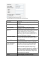
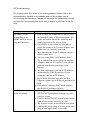
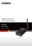
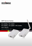
1-5 Familiar with your new wireless broadband router
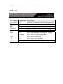
Front Panel
LED Name
(Power)
(Wireless)
WAN
LAN
1-4
LINK/ACT
Light Status
ON
On
Off
Flashing
On
Off
Flashing
On
Off
Flashing
Description
Router is switched on and correctly powered
Wireless network is switched on
Wireless network is switched off
Wireless LAN activity (transferring data)
WAN port (Internet) is running at 100Mbps
WAN port (Internet) is running at 10Mbps
WAN activity (transferring data)
LAN port is connected
LAN port is not connected
LAN activity (transferring data)
10
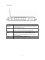
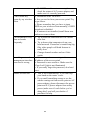
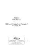
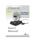
Back Panel
Item Name
Antenna
ON/OFF
12V
Reset
1-4
WAN
Description
Wireless antenna. Please keep antenna perpendicular to
the ground at all the time.
Wireless switch, Set to ‘ON’ to switch wireless function
on; set to ‘OFF’ to switch wireless function off.
Power connector, connects to power adapter
Reset the router to factory default settings (clear all
settings). Press this button and hold for 20 seconds to
clear all settings.
Local Area Network (LAN) ports 1 to 4
Wide Area Network (WAN / Internet) port
11
Chapter II: System and Network Setup
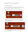
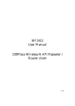
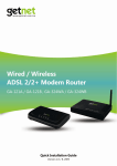
2-1 Establish network connection
Please follow the following instruction to build the network connection between
your new Broadband router and your computers, network devices:
1. Connect your xDSL / cable modem to the WAN port of router by Ethernet
cable.
2. Connect all your computers, network devices (network-enabled consumer
devices other than computers, like game console, or switch / hub) to the
LAN (1-4) port of the router.
3. Connect the power adapter to the wall socket, and then connect it to the
‘12V’ socket of the router.
12
4. Please check all LEDs on the front panel. ‘PWR’ LED should be steadily on,
WAN and LAN LEDs should be on if the computer / network device
connected to the respective port of the router is powered on and correctly
connected. If PWD LED is not on, or any LED you expected is not on,
please recheck the cabling, or jump to ‘4-2 Troubleshooting’ for possible
reasons and solution.
13
2-2 Setup client computers to obtain IP address automatically
After the network connection is established, the next step you should do is
setup the router with proper network parameters, so it can work properly in
your network environment.
Before you can connect to the router and start configuration procedures,
your computer must be able to get an IP address automatically (use dynamic
IP address). If it’s set to use static IP address, or you’re unsure, please follow
the following instructions to configure your computer to use dynamic IP
address:
If the operating system of your computer is….
Windows 95/98/Me
Windows 2000
Windows XP
Windows NT
- please go to section 2-2-1
- please go to section 2-2-2
- please go to section 2-2-3
- please go to section 2-2-4
14
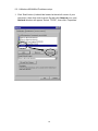
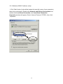
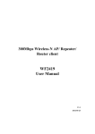
2-2-1 Windows 95/98/Me IP address setup:
1. Click ‘Start’ button (it should be located at lower-left corner of your
computer), then click control panel. Double-click Network icon, and
Network window will appear. Select ‘TCP/IP’, then click ‘Properties’.
15
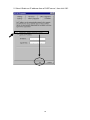
2. Select ‘Obtain an IP address from a DHCP server’, then click ‘OK’.
16
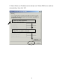
2-2-2 Windows 2000 IP address setup:
1. Click ‘Start’ button (it should be located at lower-left corner of your computer),
then click control panel. Double-click Network and Dial-up Connections icon,
double click Local Area Connection, and Local Area Connection
Properties window will appear. Select ‘Internet Protocol (TCP/IP)’, then click
‘Properties’
17
2. Select ‘Obtain an IP address automatically’ and ‘Obtain DNS server address
automatically’, then click ‘OK’.
18
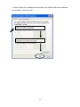
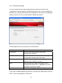
2-2-3 Windows XP IP address setup:
1. Click ‘Start’ button (it should be located at lower-left corner of your computer),
then click control panel. Double-click Network and Internet Connections icon,
click Network Connections, then double-click Local Area Connection,
Local Area Connection Statuss window will appear, and then click
‘Properties’
19
2. Select ‘Obtain an IP address automatically’ and ‘Obtain DNS server address
automatically’, then click ‘OK’.
20
2-2-4 Windows Vista IP address setup:
1. Click ‘Start’ button (it should be located at lower-left corner of your computer),
then click control panel. Click View Network Status and Tasks, then click
Manage Network Connections..Right-click Local Area Netwrok, then
select ‘Properties’. Local Area Connection Properties window will appear,
select ‘Internet Protocol Version 4 (TCP / IPv4), and then click ‘Properties’
21
2. Select ‘Obtain an IP address automatically’ and ‘Obtain DNS server address
automatically’, then click ‘OK’.
22
2-3 Connect to broadband router by web browser
Default IP address of this broadband router is ‘192.168.2.1’, and you can
connect to broadband router’s web-based configuration interface by any
connected computer with web browser (Internet Explorer 5.x or above, Firefox,
or Netscape).
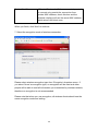
Please input ‘192.168.2.1’ in web browser’s address bar and press ‘Enter’ key
to establish connection:
You should see the following authentication window:
23
Please input ‘admin’ in ‘User name’ field, and ‘1234’ in ‘Password’ field, and
click ‘OK’ button to enter web configuration interface.
TIPS: If you can’t establish connection with broadband router with web
browser (got ‘The page cannot be displayed’ or similar error message), the IP
address you inputted may be wrong. If you’ve changed the IP address of this
broadband router previously, please input correct IP address instead of the
default IP address ’192.168.2.1’.
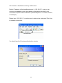
If the DHCP server function of this broadband router is enabled, please follow
the following instructions to find out the IP address of this broadband router:
24
Please click ‘start’ -> ‘run’ at the bottom-lower corner of your desktop:
Input ‘cmd’, then click ‘OK’
25
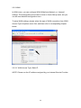
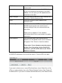
Input ‘ipconfig’, then press ‘Enter’ key. Please check the IP address followed
by ‘Default Gateway’ (In this example, the IP address of router is 192.168.2.1,
please note that this value may be different.)
NOTE: If the IP address of Gateway is not displayed, or the address followed
by ‘IP Address’ begins with ‘169’, please recheck network connection
between your computer and router, and / or go to the beginning of this
chapter, to recheck every step of network setup procedure.
If you tried the instructions listed above and still can not find the IP address of
this broadband router / you forget the password, please jump to chapter xx-xx
to reset the broadband router.
26
2-4 Using ‘Quick Setup’
This broadband router provides a ‘Quick Setup’ menu, and you can setup
basic parameters of this broadband router. Please follow the following
instructions to use ‘Quick Setup’ menu:
1.
Click ‘Quick Setup’ after logged in.
27
2. This page introduces the steps you’ll go through during Quick Setup, click
‘Next’ to start setup procedure.
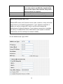
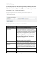
3. Check ‘Enable NTP client update’ box so this router will setup its internal
clock automatically by synchronizing with time server. Please select the time
zone of your residence from ‘Time Zone Select’ dropdown list, and then select
a nearest time server from ‘NTP server’ dropdown menu. When you finish,
click ‘Next’ to continue.
28
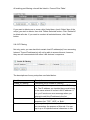
4. Please input the IP address and Subnet Mask of the LAN interface here.
You can use default setting and just click ‘Next’ to continue.
5. Please select the WAN connection type here from ‘WAN Access Type’
dropdown menu. Every connection type requires different settings. Detailed
instructions will be given below.
29
How to select the type of Internet Connection?
Static IP - You should select this connection type when our Internet Service
Provider assigns you with a specific IP address. You must know this IP address
before you can access Internet.
DHCP Client - Your Internet Service Provider requires you to use DHCP client to
obtain an IP address from them. Many Internet Service Provider which uses cable /
ADSL modem to provide Internet access will use this kind of connection.
PPPoE - Your Internet Service Provider requires you to use PPPoE client to obtain
an IP address from them. Many Internet Service Provider which uses ADSL
modem to provide Internet access will use this kind of connection.
PPTP / L2TP - Your Internet Service Provider requires you to use PPTP / L2TP
client to obtain an IP address from them. Or you want to establish a connection
with a remote PPTP / L2TP connection server.
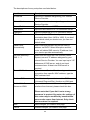
If you select ‘Static IP’ as connection type:
Item Name
Description
IP Address
Input the IP address assigned by your Internet
Service Provider. You can only use the IP address
assigned by your Internet Service Provider, or
you’ll not be able to access Internet.
Subnet Mask
Input the subnet mask assigned by your Internet
Service Provider.
30
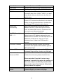
Default Gateway
Input the IP address of the default gateway
assigned by your Internet Service Provider.
DNS
Input the DNS (Domain Name System) server’s IP
address assigned by your Internet Service
Provider. DO NOT INPUT HOSTNAME HERE
(i.e. you should input something like
140.123.45.67, but not dns.somewhere.com).
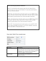
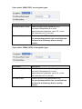
If you select ‘DHCP Client’ as connection type:
Item Name
Description
Hostname
Input the hostname. This field is optional and only
required when your Internet Service Provider
requests you to input a specific (or any) hostname.
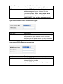
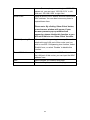
If you select ‘PPPoE’ as connection type:
Item Name
Description
User Name
Input the PPPoE user name assigned by your
Internet Service Provider.
Password
Input the PPPoE password assigned by your
Internet Service Provider.
31
If you select ‘PPTP’ as connection type:
Item Name
Description
IP Address
Input the IP address assigned by your Internet
Service Provider.
Subnet Mask
Input the subnet mask assigned by your Internet
Service Provider.
Server IP Address
Input the IP address of PPTP connection server.
User Name
Input the user name of PPTP connection server.
Password
Input the password of PPTP connection server.
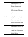
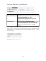
If you select ‘L2TP’ as connection type:
Item Name
Description
Attain IP Automatically
Select this option if your Internet Service Provider
will assign an IP address to you automatically by
DHCP.
Set IP Manually
Select this option if your Internet Service Provider
assigns an IP address to you and requires you to
32
use this IP address.
IP Address
Input the IP address assigned by your Internet
Service Provider.
Subnet Mask
Input the Subnet Mask assigned by your Internet
Service Provider.
Server IP Address
Input the IP address of L2TP connection server.
User Name
Input the user name of L2TP connection server.
Password
Input the password of L2TP connection server.
When you finish, click ‘Next’ to continue.
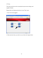
6. Please select the wireless band and mode here:
Item Name
Description
Band
Select the wireless band:
2.4GHz (B): only wireless clients with 802.11b
capability can connect to this router. Maximum
connection speed is 11Mbps.
2.4GHz (G): only wireless clients with 802.11g
capability can connect to this router. Maximum
connection speed is 54Mbps.
33
2.4GHz (B+G): Both 802.11b and 802.11g
wireless clients can connect to this router.
Mode
Select the working mode of wireless interface:
AP: This router will act as access point (serves
other wireless client’s connection needs).
Client: This router will act as wireless client
(connect to other access point as client).
WDS: This router will act as WDS (Wireless
Distribution System) station. With this capability,
this router can connect to other WDS-enabled
access point and the LAN clients on every
WDS-enabled access points can communicate
with each other.
AP+WDS: This router will act as access point with
WDS capability.
Network Type
Select the wireless network type (Infrastructure or
Ad Hoc). This option is only required when this
router is working in ‘Client’ mode.
SSID
Input the SSID (Service Set IDentifier) of this
access point (or the SSID of the access point you
wish to connect when in ‘Client’ mode).
You can input up to 32 alphanumerical characters
as SSID. SSID is used to identify this wireless
router so wireless clients can identity this router
from others.
Channel Number
Select the channel number of wireless radio. All
wireless devices who wish to communicate with
each other must use the same channel number.
It’s highly recommended to select a channel
number which is not taken by other access points,
or the wireless network performance will become
poor. To know which channels are taken by other
access points, you can use ‘Site Survey’ function
(See chapter 2-7-5) to discover which channel
numbers were taken already.
34
Enable Mac Clone
(When in Client mode) If the access point you wish
to connect only permits the connection from
certain MAC address, check this box and the
wireless interface will use the same MAC address
which wired LAN client uses.
When you finish, click ‘Next’ to continue.
7. Select the encryption mode of wireless connection:
Please select wireless encryption type from ‘Encryption’ dropdown menu. If
you select ‘None’ as encryption type, no encryption will be used and other
people will be able to read all information you transmitted by wireless network,
therefore no encryption is not recommended.
Please note that when you use encryption, all wireless clients should use the
same encryption mode and setting.
35
If you select ‘WEP’ as encryption type:
Item Name
Description
Key Length
There are two types of WEP key length: 64-bit and
128-bit. Using ‘128-bit’ is safer than ’64-bit’, but
will reduce some data transfer performance.
Key Format
There are two types of key format: ASCII and Hex.
When you select a key format, the number of
characters of key will be displayed. For example, if
you select ’64-bit’ as key length, and ‘Hex’ as key
format, you’ll see the message at the right of ‘Key
Format’ is ‘Hex (10 characters), which means the
length of WEP key is 10 characters.
Default Tx Key
You can set up to four sets of WEP key, and you
can decide which key is being used by default
here. If you don’t know which one you should
use, select ‘Key 1’.
Encryption Key 1 to 4
Input WEP key characters here, the number of
characters must be the same as the number
displayed at ‘Key Format’ field. You can use any
alphanumerical characters (0-9, a-z, and A-Z) if
you select ‘ASCII’ key format, and if you select
‘Hex’ as key format, you can use characters 0-9,
a-f, and A-F. You must enter at least one
encryption key here, and if you entered multiple
WEP keys, they should not be same with each
other.
36
If you select ‘WPA (TKIP)’ as encryption type:
Item Name
Description
Pre-shared Key Format
Select the type of pre-shared key, you
can select Passphrase (8 or more
alphanumerical characters, up to 63), or Hex
(64 characters of 0-9, and a-f).
Pre-shared Key
Please input the WPA passphrase here.
It’s not recommended to use a word that can
be found in a dictionary due to security
reason.
If you select ‘WPA2 (AES)’ as encryption type:
Item Name
Description
Pre-shared Key Format
Select the type of pre-shared key, you
can select Passphrase (8 or more
alphanumerical characters, up to 63), or Hex
(64 characters of 0-9, and a-f).
Pre-shared Key
Please input the WPA passphrase here.
It’s not recommended to use a word that can
be found in a dictionary due to security
reason.
37
If you select ‘WPA2 Mixed’ as encryption type:
Item Name
Description
Pre-shared Key Format
Select the type of pre-shared key, you
can select Passphrase (8 or more
alphanumerical characters, up to 63), or Hex
(64 characters of 0-9, and a-f).
Pre-shared Key
Please input the WPA passphrase here.
It’s not recommended to use a word that can
be found in a dictionary due to security
reason.
When you finish, click ‘OK’ to end Quick Setup procedure. It takes few seconds
for this router to save settings, when you see this message, the router is ready
with new setting:
Click ‘OK’ to start to use this router.
38
2-5 Using ‘General Setup’
The ‘General Setup’ menu provides detailed setup procedures of all functions
and settings of this router. If you want to maximize the functionality of this
router, you can use this setup menu to configure detailed settings of this router.
To enter ‘General Setup’ menu, click ‘General Setup’ icon in main menu, and
select the setup item you wish to set.
39
2-5-1 System
You can configure system related settings in ‘System’ menu.
Select the setup item you wish to set, then click ‘Next’ to continue.
2-5-1-1 Time Zone
You can setup router’s internal clock here, and you can also let router’s clock
to synchronize with time server automatically.
40
The descriptions of every setup item are listed below:
Item Name
Description
Current Time
Input current date and time manually. Please note
that this router uses 24-hour time format. (Please
input ‘23’ instead of ‘11PM’.
Time Zone Select
Please select the time zone of your residence from
this dropdown menu.
Enable NTP client
update
Check this box and this router will synchronize its
internal clock with time server automatically.
NTP Server
Select the IP address of time server from
dropdown list, or input the IP address by yourself
here. Every IP address in dropdown list comes
with the location of time server; please select the
time server which is nearest to you. If you found
the time is not correct when you select certain time
server, please select another one.
Next
Click this button to save changes you made in this
page.
Cancel
Discard all changes you made in this page.
Refresh
Reload this page, and the current date and time
setting of this router will be displayed on this page.
41
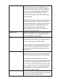
2-5-1-2 Password Settings
You can change the user name and password used to protect the web
configuration interface against unauthorized access. You can also disable the
protection so everyone who knows the IP address of this router can change its
setting. However, it’s not recommended to disable protection.
The descriptions of every setup item are listed below:
Item Name
Description
User Name
Input the user name used to enter web
configuration interface.
New Password
Input the password used to enter web
configuration interface with user name.
Confirm password
Input the password again, to make sure the
password you entered is correct.
Next
Save settings you made in this page. If you
changed user name and / or password, you’ll be
prompted to input them again.
Cancel
Discard all settings you made in this page.
If you want to disable password protection, just leave all fields blank, and click
‘Next’. You’ll be prompted to confirm this:
42
Click ‘OK’ to disable protection, or click ‘Cancel’ and this router will still ask for
user name and password before one can enter web configuration interface.
43
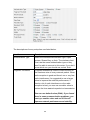
2-5-2 WAN
In WAN menu, you can configure WAN (Wide Area Network, or ‘Internet’)
settings. The settings here are similar to those in Quick Setup menu, but you
can do more detailed configuration here.
To setup WAN settings, please select the type of WAN connection from ‘WAN
Access Type’ dropdown menu first, and then refer to corresponding chapter
below.
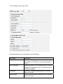
2-5-2-1 WAN Access Type: Static IP
NOTE: Please use the IP address assigned by your Internet Service Provider.
44
The descriptions of every setup item are listed below:
Item Name
Description
IP Address
Input the IP address assigned by Internet Service
Provider.
Subnet Mask
Input the subnet mask assigned by your Internet
Service Provider.
Default Gateway
Input the IP address of the default gateway
assigned by your Internet Service Provider.
DNS 1 - 3
Input the DNS (Domain Name System) server’s IP
address assigned by your Internet Service
Provider. You can input up to 3 IP addresses of
DNS server, and do not input hostname here. At
lease one DNS server is required.
Clone MAC Address
If your Internet Service Provider only permits
connection from specific MAC address, type the
MAC address here.
Enable uPNP
Check this box if you wish to enable uPNP
(Universal Plug-and-Play) function on WAN port.
Enable Web Server
Access on WAN
If you wish to connect to the web configuration
interface from Internet, please check this box.
Please note that if you didn’t set a strong
password to protect this router, the settings of
this router may be modified by unauthorized
person who comes from Internet. Only check
this box when it’s required.
Next
Save changes you made in this page.
Cancel
Discard changes you made in this page.
45
2-5-2-2 WAN Access Type: DHCP Client
The descriptions of every setup item are listed below:
Item Name
Description
Hostname
Input the hostname of router. This is optional
(should not be required in most cases, unless
required by your Internet Service Provider).
Obtain DNS
Automatically
Most of service provider will provide DNS IP
address via DHCP. Select this option and this
router will obtain DNS server’s IP address from
your service provider automatically.
Set DNS Manually /
DNS 1 - 3
Select this and input the DNS (Domain Name
System) server’s IP address assigned by your
Internet Service Provider. You can input up to 3 IP
addresses of DNS server, and do not input
hostname here. At least one DNS server is
required.
Clone MAC Address
If your Internet Service Provider only permits
connection from specific MAC address, type the
MAC address here.
Enable uPNP
Check this box if you wish to enable uPNP
(Universal Plug-and-Play) function on WAN port.
Enable Web Server
Access on WAN
If you wish to connect to the web configuration
interface from Internet, please check this box.
46
Please note that if you didn’t set a strong
password to protect this router, the settings of
this router may be modified by unauthorized
person who comes from Internet. Only check
this box when it’s required.
Next
Save changes you made in this page.
Cancel
Discard changes you made in this page.
2-5-2-3 WAN Access Type: PPPoE
The descriptions of every setup item are listed below:
Item Name
Description
User Name
Input PPPoE user name assigned by your Internet
Service Provider.
Password
Please input the password assigned by your
Internet Service Provider.
Service Name
Please give a name to this Internet service, this is
optional.
47
Connection Type
Please select the connection type of Internet
connection you wish to use. There are 3 options:
‘Continuous’ - keep internet connection alive, do
not disconnect.
’Connect on Demand’ - only connects to Internet
when there’s a connect attempt,
Manual - only connects to Internet when ‘Connect’
button on this page is pressed, and disconnects
when ‘Disconnect button is pressed.
Idle Time
Please specify the time to shutdown Internet
connect after no internet activity is detected in
minute(s) from 1 to 1000. This option is only
available when connection type is ‘Connect on
Demand’.
MTU Size
Please input the MTU value of your network
connection here (from 1400 to 1492). If you don’t
know which value you should use, you can use
default value.
Obtain DNS
Automatically
Most of service provider will provide DNS IP
address via DHCP. Select this option and this
router will obtain DNS server’s IP address from
your service provider automatically.
Set DNS Manually /
DNS 1 - 3
Select this and input the DNS (Domain Name
System) server’s IP address assigned by your
Internet Service Provider. You can input up to 3 IP
addresses of DNS server, and do not input
hostname here. At least one DNS server is
required.
Clone MAC Address
If your Internet Service Provider only permits
connection from specific MAC address, type the
MAC address here.
Enable uPNP
Check this box if you wish to enable uPNP
(Universal Plug-and-Play) function on WAN port.
Enable Web Server
Access on WAN
If you wish to connect to the web configuration
interface from Internet, please check this box.
Please note that if you didn’t set a strong
48
password to protect this router, the settings of
this router may be modified by unauthorized
person who comes from Internet. Only check
this box when it’s required.
Next
Save changes you made in this page.
Cancel
Discard changes you made in this page.
How to choose a proper MTU size?
Default MTU value (1412) works in most cases, however, it may not be the
best choice in your network environment. If your Internet connection is
stable, you can try a larger MTU value, and this will increase the
performance of network. However, if your Internet connection is unstable,
you can try a smaller MTU value, there will be some impact on network
performance, but this will improve network stability.
2-5-2-4 WAN Access Type: PPTP
49
The descriptions of every setup item are listed below:
Item Name
Description
IP Address
Input the IP address assigned by your Internet
Service Provider.
Subnet Mask
Input the subnet mask assigned by your Internet
Service Provider.
Server IP Address
Input the IP address of PPTP connection server.
User Name
Input the user name of PPTP connection server.
Password
Input the password of PPTP connection server.
MTU Size
Please input the MTU value of your network
connection here (from 1400 to 1492). If you don’t
know which value you should use, you can use
default value.
Obtain DNS
Automatically
Most of service provider will provide DNS IP
address via DHCP. Select this option and this
router will obtain DNS server’s IP address from
your service provider automatically.
Set DNS Manually /
DNS 1 - 3
Select this and input the DNS (Domain Name
System) server’s IP address assigned by your
Internet Service Provider. You can input up to 3 IP
addresses of DNS server, and do not input
hostname here. At least one DNS server is
required.
Clone MAC Address
If your Internet Service Provider only permits
connection from specific MAC address, type the
MAC address here.
Enable uPNP
Check this box if you wish to enable uPNP
(Universal Plug-and-Play) function on WAN port.
Enable Web Server
Access on WAN
If you wish to connect to the web configuration
interface from Internet, please check this box.
Please note that if you didn’t set a strong
password to protect this router, the settings of
this router may be modified by unauthorized
person who comes from Internet. Only check
this box when it’s required.
Next
Save changes you made in this page.
Cancel
Discard changes you made in this page.
50
2-5-2-5 WAN Access Type: L2TP
The descriptions of every setup item are listed below:
Item Name
Description
Attain IP Automatically
Select this option if your Internet Service Provider
will assign an IP address to you automatically by
DHCP.
Set IP Manually
Select this option if your Internet Service Provider
assigns an IP address to you and requires you to
use this IP address.
IP Address
Input the IP address assigned by your Internet
Service Provider.
Subnet Mask
Input the Subnet Mask assigned by your Internet
Service Provider.
51
Server Address
Input the IP address of L2TP connection server.
User Name
Input the user name of L2TP connection server.
Password
Input the password of L2TP connection server.
MTU Size
Please input the MTU value of your network
connection here (from 1400 to 1492). If you don’t
know which value you should use, you can use
default value.
Disconnect after
Check this box and this router will disconnect
current L2TP connection after there’s no network
activity for the time specified here. Uncheck this
box to keep L2TP connection alive forever.
Obtain DNS
Automatically
Most of service provider will provide DNS IP
address via DHCP. Select this option and this
router will obtain DNS server’s IP address from
your service provider automatically.
Set DNS Manually /
DNS 1 - 3
Select this and input the DNS (Domain Name
System) server’s IP address assigned by your
Internet Service Provider. You can input up to 3 IP
addresses of DNS server, and do not input
hostname here. At least one DNS server is
required.
Clone MAC Address
If your Internet Service Provider only permits
connection from specific MAC address, type the
MAC address here.
Enable uPNP
Check this box if you wish to enable uPNP
(Universal Plug-and-Play) function on WAN port.
Enable Web Server
Access on WAN
If you wish to connect to the web configuration
interface from Internet, please check this box.
Please note that if you didn’t set a strong
password to protect this router, the settings of
this router may be modified by unauthorized
person who comes from Internet. Only check
this box when it’s required.
Next
Save changes you made in this page.
Cancel
Discard changes you made in this page.
52
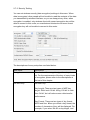
2-6 LAN
You can change LAN (Local Area Network) settings here.
The descriptions of every setup item are listed below:
Item Name
Description
IP Address
Input the IP address of the LAN port of this router
here.
Subnet Mask
Input the subnet mask of the LAN port of this
router here.
Default Gateway
In most cases, this router will be the default
gateway of other network clients, and you don’t
have to input the gateway IP address here (use
default value 0.0.0.0). However, if you want your
network clients to use other IP address as default
gateway address, you can input its IP address
here, and network clients will use the IP address
listed here as default gateway.
DHCP
There are 3 options:
Disabled: Disable DHCP server / client function.
Client: This router will become a DHCP client and
obtain IP address information from DHCP server.
Server: This router will become DHCP server and
give IP address information (DHCP leases) to
DHCP clients.
DHCP Client Range
Input the start and end IP address of DHCP
53
leases. For example, you want to give 100 DHCP
leases out, you can input ‘192.168.2.101’ in left
field and ‘192.168.2.200’ in right field.
Show Client
Show all active DHCP leases and their associated
MAC address. You can also know every lease’s
expired lease time.
Please note: By clicking ‘Show Client’ button,
a new browser window will appear. If your
browser prevents pop-up window from
appearing, please disable this function or you
will not be able to use ‘Show Client’ function.
802.11d Spanning Tree
If there’s 802.11d spanning tree compatible switch
attached to any LAN port of this router, and you
wish to use 802.11d spanning tree function, select
‘Enable’ here, or select ‘Disable’ to disable this
function.
Close MAC Address
If you wish to use customized MAC address for
the LAN port of this router, you can input the MAC
address here.
Next
Save changes you made in this page.
Cancel
Discard changes you made in this page.
54
2-7 Wireless
In wireless menu, you can setup wireless functions like SSID and wireless
security. When you want to use this router as wireless client and connect to
other access point, you can also scan for access points by wireless setup
menu.
Please select the setup item you wish to set, then click ‘Apply’ to continue.
55
2-7-1 ‘Basic’ Settings
In this menu, you can setup basic wireless parameters.
The descriptions of every setup item are listed below:
Item Name
Description
Band
Select the wireless band:
2.4GHz (B): only wireless clients with 802.11b
capability can connect to this router. Maximum
connection speed is 11Mbps.
2.4GHz (G): only wireless clients with 802.11g
capability can connect to this router. Maximum
connection speed is 54Mbps.
2.4GHz (B+G): Both 802.11b and 802.11g
wireless clients can connect to this router.
Mode
Select the working mode of wireless interface:
AP: This router will act as access point (serves
other wireless client’s connection needs).
Client: This router will act as wireless client
(connect to other access point as client).
56
WDS: This router will act as WDS (Wireless
Distribution System) station. With this capability,
this router can connect to other WDS-enabled
access point and the LAN clients on every
WDS-enabled access points can communicate
with each other.
AP+WDS: This router will act as access point with
WDS capability. When in WDS-only mode, this
router will not be able to accept the connection of
wireless clients; when in AP+WDS mode, this
router will be able to connect with other
WDS-enabled access points, and accept the
connection of wireless clients.
Network Type
Select the wireless network type (Infrastructure or
Ad Hoc). This option is only required when this
router is working in ‘Client’ mode.
SSID
Input the SSID (Service Set IDentifier) of this
access point (or the SSID of the access point you
wish to connect when in ‘Client’ mode).
You can input up to 32 alphanumerical characters
as SSID. SSID is used to identify this wireless
router so wireless clients can identity this router
from others.
Channel Number
Select the channel number of wireless radio. All
wireless devices who wish to communicate with
each other must use the same channel number.
It’s highly recommended to select a channel
number which is not taken by other access points,
or the wireless network performance will become
poor. To know which channels are taken by other
access points, you can use ‘Site Survey’ function
(See chapter 2-7-5) to discover which channel
numbers were taken already.
Associated Clients
When this router is working in ‘AP’ or ‘AP+WDS’
mode, you can click ‘Show Active Clients’ button to
show all connected wireless clients.
57
Please note: By clicking ‘Show Active Clients’
button, a new browser window will appear. If
your browser prevents pop-up window from
appearing, please disable this function or you
will not be able to use ‘Show Client’ function.
Enable Mac Clone
(When in Client mode) If the access point you wish
to connect only permits the connection from
certain MAC address, check this box and the
wireless interface will use the same MAC address
which wired LAN client uses.
Enable Universal
Repeater Mode
If you want this router to act as wireless client
(connect to other access point) and access point
(serve wireless client’s communication needs),
check this box, and this router will act as access
point and wireless client at the same time.
SSID of Extended
Interface
When you enable “Enable Universal Repeater
Mode” , please input the Access Point’s SSID
which BR-6204WLg would like connect.
Next
Save changes you made in this page.
Cancel
Discard changes you made in this page.
2-7-2 ‘Advanced’ Setting
In this menu, you can configure advanced settings of wireless interface.
Please note that the settings in this page are designed for experienced
users, and this wireless router is able to work without any problem when
all settings in this menu are unchanged. Only modify the settings in this
page when you understand the setup item’s purpose.
58
The descriptions of every setup item are listed below:
Item Name
Description
Authentication Type
Select the wireless authentication type: Open
system, Shared Key, or Auto. The wireless client
must use the same authentication type or they
won’t be able to connect to this router. If you don’t
know which one you should use, select ‘Auto’.
Fragment Threshold
Fragment threshold is used to control the size of
the maximum size of every network packet. When
radio reception is good and there’s no or very few
radio interference, it’s suggested to use a larger
value to improve the network performance; if
there’s a lot of radio interference or the radio
reception is bad, you can use a smaller value to
reduce the time wasted on packet re-transmission.
You can use default value (2346). If you found
there’re some communication problems, you
can try a smaller value and see if this will
improve network performance and stability.
59
RTS Threshold
RTS threshold is used to decide the time interval
between every RTS (Request to Send) packets.
Using a smaller value will cause the wireless
router to send RTS packets more often, and all
wireless stations will be able to recover from
collision (two stations send the packet at the same
time, which will destroy transmitted data packet)
more quickly.
However, sending RTS packets too often will
reduce the performance of wireless network, and
you should only use a smaller value when there’re
a lot of wireless stations connected to this wireless
router. It’s safe to use default value (2347) when
there are less then 10 wireless clients.
When you wish to decrease the RTS threshold
value to improve network performance and
stability, please decrease ‘Fragment
Threshold’ value also.
Beacon Interval
Beacon Interval is used to control the time interval
between every beacon packet. If you use a
smaller value, this wireless router will send the
beacon packet more often, and wireless clients
can found this wireless router quickly; If you use a
larger value, wireless clients will have to scan for
more times before it can find this wireless router.
By using a larger value, there will be lesser
beacon packets sent by this wireless router, and
the network performance will be better.
Data Rate
Please select the wireless data rate from
dropdown list. You can select a fixed data rate and
all wireless clients must use this data rate to
communicate with wireless router.
It’s recommended to select ‘Auto’ and let
wireless client / router to decide the
communication speed by actual radio
reception.
60
Preamble Type
Select the preamble type (long or short) for the
network packet. When you’re using this router in a
heavily-loaded network environment, select ‘Short
preamble’ will help to improve network
performance.
However, not every network client works with
short preamble (especially certain 802.11b
only wireless clients). If you found that some
wireless clients can’t connect to this router
when you select ‘Short Preamble’, please
select ‘Long Preamble’.
Broadcast SSID
By selecting ‘Enabled’ here, this router will
broadcast its SSID to all wireless clients so they
can connect to this router. However, there will be
some security risk to let everyone know this
router’s SSID.
By selecting ‘Disabled’ here, this router will not
broadcast its SSID, so only client who know this
router’s SSID is able to connect to this router, and
therefore security level is improved.
IAPP
IAPP stands for Inter-Access Point Protocol, If
your wireless clients will roam between access
points, you can select ‘Enabled’ here.
802.11g Protection
When this wireless router is working in 802.11B +
802.11G mode, it’s high recommended to enable
802.11g protection to prevent data collision, and
this will improve network stability and
performance.
WMM
Select ‘Enabled’ to enable support for WMM
(Wireless MultiMedia). This will improve the
performance of video / audio data transmission.
61
RF Output Power
Select the radio output power. If all wireless clients
are not far away from wireless router, you can
select a lower output power to save energy and
prevent other people to scan your wireless router
from distant.
Turbo Mode
Turbo Mode will increase the performance of
wireless data transmission . You can set this
option to ‘Always’ and this router will switch turbo
mode on infinitely, but some wireless clients which
are not compatible with Turbo Mode may not be
able to connect to this router. It’s recommended to
select ‘Auto’ to let this wireless router to switch
turbo mode on when wireless client supports it.
Currently, this function only works with Realtek
wireless network cards.
Next
Save changes you made in this page.
Cancel
Discard changes you made in this page.
62
2-7-3 ‘Security’ Setting
You can set wireless security (data encryption) settings in this menu. When
data is encrypted, other people will not be able to read the contents of the data
you transmitted by wireless interface, so you can keep privacy. Also, when
encryption is enabled, only wireless client with correct encryption key will be
able to connect to this router, so unauthorized clients who do know correct
encryption key will not be able to connect to this router.
The descriptions of every setup item are listed below:
Item Name
Description
Encryption
Please select the encryption type from dropdown
list. For the requirements of the key of every kinds
of encryption, please refer to the descriptions at
the last of this chapter.
Set WEP Key
Set WEP key:
Key Length: There are two types of WEP key
length: 64-bit and 128-bit. Using ‘128-bit’ is safer
than ’64-bit’, but will reduce some data transfer
performance.
Key Format: There are two types of key format:
ASCII and Hex. When you select a key format, the
number of characters of key will be displayed. For
example, if you select ’64-bit’ as key length, and
63
‘Hex’ as key format, you’ll see the message at the
right of ‘Key Format’ is ‘Hex (10 characters), which
means the length of WEP key is 10 characters.
Default Tx Key: You can set up to four sets of
WEP key, and you can decide which key is being
used by default here. If you don’t know which one
you should use, select ‘Key 1’.
Encryption Key 1 to 4: Input WEP key characters
here, the number of characters must be the same
as the number displayed at ‘Key Format’ field. You
can use any alphanumerical characters (0-9, a-z,
and A-Z) if you select ‘ASCII’ key format, and if
you select ‘Hex’ as key format, you can use
characters 0-9, a-f, and A-F. You must enter at
least one encryption key here, and if you entered
multiple WEP keys, they should not be same with
each other.
When you finish, click ‘Apply’ button to save
changes; click ‘Close’ to close WEP key setup
window, or click ‘Reset’ to clear the content of
every field in this page.
Use 802.1x
Authentication
Check this box to use 802.1x authentication
instead of local WEP key. You also have to select
the length of WEP key (64bits or 128bits), and
setup the IP address and login information of
RADIUS authentication server below.
This option works with WEP encryption only.
WPA Authentication
Mode
Select the type of WPA authentication (Enterprise /
Using RADIUS sever) or PSK (Pre-shared key). If
you don’t have RADIUS authentication server,
please select PSK.
This option works with WPA encryption only.
64
WPA Cipher Suite
Select the cipher suite of WPA encryption (TKIP or
AES)
This option works with WPA encryption only.
WPA2 Cipher Suite
Select the cipher suite of WPA2encryption (TKIP
or AES)
This option works with WPA2 encryption only.
Pre-shared Key Format
Select the format of WPA/WPA2 pre-shared key
(Passphrase or Hex). If you select ‘Passphrase’,
you have to input 8 to 63 alphanumerical
characters; If you select ‘Hex’, you have to input
64 characters of 0-9 and a-f.
Pre-shared Key
Input WPA/WPA2 pre-shared key here.
Enable
Pre-Authentication
Enable Pre-Authentication function.
Authentication RADIUS
Server
Input the port number, IP address, and password
of RADIUS authentication server here.
Next
Save changes you made in this page.
Cancel
Discard changes you made in this page.
2-7-4 ‘Access Control’ Setting
You can use this menu to restrict the client to connect to this wireless router by
checking its MAC address.
There are two kinds of access control: Allow listed MAC address only, and
deny listed MAC address only.
The descriptions of every setup item are listed below:
Item Name
Description
65
Wireless Access Control Select the access control mode from dropdown
Mode
list. Available options are:
Disable: Disable access control.
Allow Listed: Only MAC addresses listed here will
be able to connect to this router.
Deny Listed: Only MAC addresses listed here will
not be able to connect to this router.
MAC Address
Input the MAC address to add to the list.
Comment
Input descriptive text for this MAC address, so you
can remember who owns this MAC address. This
is optional and you can leave it blank. You can
input up to 20 alphanumerical characters in this
field.
Next
Add the MAC address and associated comment to
the list.
Cancel
Discard all settings you made in this page.
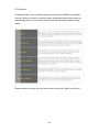
All MAC addresses in the list will be listed in ‘Current Access Control List’ table:
If you want to delete one or more address(es) listed here, check ‘Select’ box of
the address(es) you wish to delete, then click ‘Delete Selected’ button; Click
‘Delete All’ to delete all addresses. If you want to unselect all selected boxes,
click ‘Reset’ button.
2-7-5 Site Survey
When this router enables wireless client mode, you can use this function to
scan for all reachable access points, and connect to selected access point.
When you enter ‘Site Survey’ menu, please see if the access point you wish to
66
connect is listed. If not, please click ‘Refresh’ button. You may have to click
‘Refresh button for several times before the access point you wish to connect
appears.
When the access point you wish to connect appears, click ‘Select’ of that
access point, then click ‘Connect’ button. This router will use current
encryption setting to connect to selected access point.
2-7-6 WDS Setting
This wireless router supports WDS (Wireless Distribution System). You can
connect this router with other WDS-enabled wireless access point, and all
clients (wireless & wired) of every WDS-enabled wireless access point can
communicate with each other. Therefore, you can use WDS to extend the
range and scope of your network.
To use WDS, you must select ‘WDS’ or ‘AP+WDS’ as working mode (as
described in chapter 2-7-1). WDS function will not work in other working
modes.
The descriptions of every setup item are listed below:
Item Name
Description
Enable WDS
Check this box to enable WDS function. This
option is only available when the working mode of
this router is ‘WDS’ or ‘AP+WDS’.
67
MAC Address
Input the MAC address of other WDS-enabled
access point.
Comment
Input any descriptive text about this MAC address,
so you can remember the purpose of this MAC
address. You can input up to 20 alphanumerical
characters in this field.
Apply Changes
Click this button to add above MAC address and
comment to WDS access point list.
Reset
Clear the contents of ‘MAC Address’ and
Comment’ field.
Set Security
Click this button to set WDS security (encryption).
All WDS access points must use the same
security setting so they can communicate with
each other.
Please refer to chapter 2-7-3 for detailed
instructions about how to input proper encryption
parameters.
Show Statistics
Click this button and a new window with all
statistics (Tx / Rx packet counts, error counts etc.)
will appear. Click ‘Close’ to close the window.
Please note: If your browser prevents pop-up
window from appearing, please disable this
function or you will not be able to use 'Show
Statistics' function.
All WDS AP addresses in the list will be listed in ‘Current WDS List’ table:
If you want to delete one or more AP(s) listed here, check ‘Select’ box of the
AP(s) you wish to delete, then click ‘Delete Selected’ button; Click ‘Delete All’
to delete all AP. If you want to unselect all selected boxes, click ‘Reset’ button.
68
2-8 Advanced Settings
This router provides several advanced network functionalities like port
forwarding and IP filtering. You can use these functions to control your network
in detail.
Please select the setup item you wish to set, then click ‘Apply’ to continue.
69
2-8-1 Port Filtering
By using this function, you can restrict certain types of outbound (from LAN to
Internet) traffic by blocking specific ports. For example, if you don’t want your
LAN devices and computers to access FTP servers on Internet, you can add
port number ‘20’ and ‘21’ to the port filtering list.
For port numbers of common services, please refer to chapter 4-3
‘Well-Known Services’.
The descriptions of every setup item are listed below:
Item Name
Description
Enable Port Filtering
Check this box to enable port filtering.
Port Range
Input the port range to be included in this port
filtering rule. Please input the starting port number
in the left field, and input the ending port number in
the right field. For example, if you want to block
port 20 to 40, input ‘20’ in the left field and input
‘40’ in the right field. If you only want to block a
single port number for this rule, input the port
number in the left field.
Valid port number is from 1 to 65535.
Protocol
Please select the protocol type you want to block
for this rule. You can select ‘TCP’, ‘UDP’ or both.
Comment
Input any descriptive text about this rule, so you
can remember the purpose of this rule. You can
input up to 20 alphanumerical characters in this
field.
Next
Add the MAC address and associated comment to
the list.
Cancel
Discard all settings you made in this page.
70
All existing port filtering rules will be listed in ‘Current Filter Table’:
If you want to delete one or more rule(s) listed here, check ‘Select’ box of the
rule(s) you wish to delete, then click ‘Delete Selected’ button; Click ‘Delete All’
to delete all rules. If you want to unselect all selected boxes, click ‘Reset’
button.
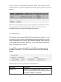
2-8-2 IP Filtering
Not only ports, you can also block certain local IP address(es) from accessing
Internet. These IP address(es) will not be able to access Internet, however,
they can still communicate with other LAN devices / computers.
The descriptions of every setup item are listed below:
Item Name
Description
Enable IP Filtering
Check this box to enable IP filtering.
Local IP Address
Input the IP address you wish to add to IP filtering
list. The IP address you inputted here must belong
to the same subnet of current LAN IP address. If
not, you’ll receive an error message when you
attempt to add this IP address to the list.
Protocol
Select the protocol type you wish to block from
dropdown list: ‘TCP’, ‘UDP’, or ‘Both’.
Comment
Input any descriptive text about this rule, so you
can remember the purpose of this rule. You can
input up to 20 alphanumerical characters in this
71
field.
Next
Add the IP address and associated comment to
the list.
Cancel
Discard all settings you made in this page.
All existing IP filtering rules will be listed in ‘Current Filter Table’:
If you want to delete one or more rule(s) listed here, check ‘Select’ box of the
rule(s) you wish to delete, then click ‘Delete Selected’ button; Click ‘Delete All’
to delete all rules. If you want to unselect all selected boxes, click ‘Reset’
button.
2-8-3 MAC Filtering
Similar to IP filtering, you can block devices / computers with certain MAC
address from accessing Internet.
The descriptions of every setup item are listed below:
Item Name
Description
Enable MAC Filtering
Check this box to enable MAC filtering.
MAC Address
Input the MAC address you wish to add to MAC
filtering list.
Comment
Input any descriptive text about this rule, so you
can remember the purpose of this rule. You can
input up to 20 alphanumerical characters in this
72
field.
Next
Add the IP address and associated comment to
the list.
Cancel
Discard all settings you made in this page.
All existing MAC filtering rules will be listed in ‘Current Filter Table’:
If you want to delete one or more rule(s) listed here, check ‘Select’ box of the
rule(s) you wish to delete, then click ‘Delete Selected’ button; Click ‘Delete All’
to delete all rules. If you want to unselect all selected boxes, click ‘Reset’
button.
2-8-4 Port Forwarding
This router uses ‘NAT’ (Network Address Translation) to let all devices and
computers on LAN to access Internet. Normally, this is a one-way translation Computers on LAN can access Internet, but computer comes from Internet will
not be able to access computers on LAN.
Sometimes you’ll need to let computers from Internet to access certain ports
on LAN, so you can provide services to general public. In this case, you can
use ‘Port Forwarding’ function and computer from Internet can access certain
services on LAN.
For port numbers of common services, please refer to chapter 4-3
‘Well-Known Services’.
73
The descriptions of every setup item are listed below:
Item Name
Description
Enable Port Forwarding
Check this box to enable Port forwarding.
IP Address
Input the IP address on LAN you wish to provide
services to computers from Internet.
Protocol
Select the protocol type you wish to block from
dropdown list: ‘TCP’, ‘UDP’, or ‘Both’.
Port Range
Input the port range to be included in this port
forwarding rule, the port number you inputted here
will be mapped to the WAN IP address used by
this router. Please input the starting port number in
the left field, and input the ending port number in
the right field. For example, if you want to block
port 20 to 40, input ‘20’ in the left field and input
‘40’ in the right field. If you only want to block a
single port number for this rule, input the port
number in the left field.
Valid port number is from 1 to 65535.
Comment
Input any descriptive text about this rule, so you
can remember the purpose of this rule. You can
input up to 20 alphanumerical characters in this
field.
Next
Add the IP address and associated comment to
the list.
Cancel
Discard all settings you made in this page.
All existing Port forwarding rules will be listed in ‘Current Port Forwarding
Table’:
If you want to delete one or more rule(s) listed here, check ‘Select’ box of the
rule(s) you wish to delete, then click ‘Delete Selected’ button; Click ‘Delete All’
to delete all rules. If you want to unselect all selected boxes, click ‘Reset’
74
button.
2-8-5 DMZ
DMZ (Demilitarized Zone) is a special IP address on LAN. Computer from
Internet can access all services on this IP address, just like this IP address is
the same as the IP address used by the WAN interface of this router. You can
use this function to setup a server on LAN, and it will be able to be accessed
by any computer from Internet.
This router only capable to use one IP address for WAN port, therefore only
one DMZ host is allowed.
Please note that computer using DMZ IP address is no longer protected
by the built-in firewall of this router, it must be able to protect itself from
attacks.
The descriptions of every setup item are listed below:
Item Name
Description
Enable DMZ
Check this box to enable DMZ function.
DMZ Host IP Address
Input the IP address on LAN you wish to set as
DMZ host.
Next
Save DMZ settings.
Cancel
Discard all settings you made in this page.
2-8-6 DDNS
DDNS (Dynamic DNS) is a kind of service which provides hostname-to-IP
service to ‘dynamic’ IP address users. ‘Dynamic IP’ means Internet service
subscriber will obtain different IP address when he or she connects to Internet.
Due to this nature, it will be difficult for dynamic IP users to provide services to
75
general public, because the IP address is always changing.
DDNS service maps ever-changing IP address to a fixed hostname, so people
who wants to access the service provides by dynamic IP users just need to
remember the fixed hostname, and don’t have to worry about the fact of IP
address will be changed next time.
This router supports two kinds of DDNS service provider, please go to their
service webpage and follow their instructions to register a new DDNS account
to use their service:
TZO: http://www.tzo.com
DynDNS: http://www.dyndns.org
You can also click the text in DDNS menu to access TZO and DynDNS website
(pointed by arrow)
After you obtained a valid hostname, user name, and account from one of
DDNS services, you can use ‘DDNS’ menu to use DDNS service.
The descriptions of every setup item are listed below:
Item Name
Description
Enable DDNS
Check this box to enable DDNS function.
Domain Name
Input the domain name (host name) obtained from
DDNS service provider.
User Name / Email
Input the user name / Email you used to register
DDNS service.
Password / Key
Input the password / key you used to register
76
DDNS service.
Next
Save DDNS settings.
Cancel
Discard all settings you made in this page.
77
Chapter III
Advanced Operation Techniques
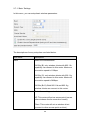
3-1 Status
This broadband router provides a ‘status’ menu, and you can check all
system-wide status and statistics of this broadband router. Please follow the
following instructions to use ‘Status’ menu:
1. Click ‘Status’ after logged in.
2. Select one status item you wish to check, and then click ‘Apply’ button.
78
3-1-1 Status Information
You can check current system-wide status of this router here.
79
3-1-2 System Log
This router logs all important system events here, and you can even decide
which kind of event this router will log. Optionally, you can save the log to a
remote syslog server to keep and maintain the log.
The descriptions of every setup item are listed below:
Item Name
Description
Enable Log
Check this box to enable log function.
Wireless only
Select this to log wireless-related events only.
System all
Select this to log all system-wide events.
Enable Remote Log
Check this box to send the log to a remote syslog
server.
Log Server IP Address
Input the IP address of the syslog server you wish
to send log to.
Apply Changes
Save changes you made in this page.
Refresh
Reload logs.
Clear
Clear existing logs.
80
3-1-3 Statistics
In this menu you can see the statistics of all network interfaces.
The descriptions of every setup item are listed below:
Item Name
Description
Refresh
Reload statistics.
81
3-2 Tools
This router provides two tools: save/reload current router settings, and
upgrade firmware.
Please follow the following instructions to use ‘Tools’ menu:
1. Click ‘Tools’ after logged in.
2. Select one tools item you wish to use, and then click ‘Apply’ button.
82
3-2-1 Save/Reload Settings
You can save current system settings to a file, or load a previously-saved
system setting from a file.
You can also reset all settings of this router and restore to factory default
settings. If you want to give this router to other people, you can use this
function to clear all settings, to prevent other people to know your security
settings. When this router is not working properly, reset all settings may solve
the problem if the source of problem is improper setting.
The descriptions of every setup item are listed below:
Item Name
Description
Save Settings to File
Click ‘Save’ button to save current router settings
to a file. You’ll be prompted to save the file as
‘config.dat’, click ‘Save’ button to select destination
folder to save the file when you’re prompted. You
have chance to change the filename when you’re
choosing the destination folder.
Load Settings from File
Click ‘Browse’ button to select a previously-saved
router setting file, then click ‘Upload’ to upload the
setting file to the router.
Reset Settings to
Click ‘Reset’ button to clear all settings of this
83
Default
router. You’ll be prompted to confirm reset, click
‘OK’ to clear all settings or ‘Cancel’ to keep current
settings untouched.
84
3-2-2 Firmware Upgrade
To upgrade firmware, please make sure you have firmware file ready in your
computer’s hard drive. When you’re ready, enter ‘Upgrade Firmware’ menu to
upload new firmware file to the router.
Click ‘Browse…’ button to select a firmware file to upload. You’ll be prompted
to select the firmware file from computer’s hard disk:
After you selected the file, click ‘Open’. You’ll return to previous menu, click
‘Upload’ now to start uploading firmware file:
85
The upload procedure will take few minutes, please be patient. After the file is
fully uploaded, you’ll see the following message, indicating the firmware file is
successfully uploaded. Please wait for 1 minute and click ‘OK’ button; your
router will be ready with new firmware.
86
Chapter IV Appendix
4-1 Specifications
87
4-2 Troubleshooting
Do not panic when this router is not working properly! Please refer to the
troubleshooting checklist in this chapter, and find the problem you’re
encountering and its solution. Maybe you can solve the problem by yourself
and save the time sending this router back to dealer of purchase to ask for
help.
Scenario
The router is not
responding to me
when I want to access
it by web browser
Can’t get connected to
router wirelessly
Solution
a. Please check the connection of power cord
and network cable of this access point. All
cords and cables should be correctly and
firmly inserted to the access point.
b. If all LEDs on the router are out, please
check the status of A/C power adapter, and
make sure it’s correctly powered.
c. You must use the same IP address section
which router uses.
d. Are you using MAC or IP address filter?
Try to connect the access point by another
computer and see if it works; if not, please
perform a hard reset (pressing ‘reset’
button).
e. Set your computer to obtain an IP address
automatically (DHCP), and see if your
computer can get an IP address.
f. If you did a firmware upgrade and this
happens, contact your dealer of purchase for
help.
g. If all above solutions don’t work, contact
the dealer of purchase for help.
a. If encryption is enabled, please re-check
WEP or WPA passphrase settings on your
wireless client.
b. Check wireless On/Off switch located at the
back of this router. Switch it to ‘On’.
c. Try to move closer to wireless access point.
d. Unplug the power plug of access point, and
plug it back again after 10 seconds.
88
e. If all LEDs on the router are out, please
check the status of A/C power adapter, and
make sure it’s correctly powered.
I can’t locate my
a. ‘Broadcast SSID’ set to off?
router by my wireless b. Are you too far from your access point? Try
client
to get closer.
c. Please remember that you have to input
SSID on your wireless client manually, if SSID
broadcast is disabled.
d. If antenna is not installed, install them now
and never remove them.
File download is very a. Try to reset the router and see if it’s better
slow or breaks
after that.
frequently
b. Try to know what computers do on your
local network. If someone’s transferring big
files, other people will think Internet is
really slow.
c. Change channel number and see if this
works.
I can’t log onto web
a. Make sure you’re connecting to the correct
management interface: IP address of the access point!
password is wrong
b. Password is case-sensitive. Make sure the
‘Caps Lock’ light is not illuminated.
c. If you really forget the password, do a hard
reset.
Router become hot
a. This is not a malfunction, if you can keep
your hand on the router’s case.
b. If you smell something wrong or see the
smoke coming out from access point or A/C
power adapter, please disconnect the access
point and A/C power adapter from utility
power (make sure it’s safe before you’re
doing this!), and call your dealer of
purchase for help.
89
4-3 Well-Known Services
This table lists all well-known Internet services. Please note that some services
may use other ports instead of ‘standard’ port number. Refer to the technical
document of the service program you’re using, to make sure the port number it
uses.
Port Number
7
Description
Echo
11
systat
13
Daytime
19
chargen
20
ftp-data
21
ftp
22
Ssh
23
Telnet
25
SMTP
37
Time
53
DNS
63
Whois
69
TFTP
80
HTTP
110
POP3
119
NNTP
123
NTP
137
Netbios-NS
138
Netbios-DGM
139
Netbios-SSN
143
IMAP
161
SNMP
90
Federal Communication Commission Interference Statement
This equipment has been tested and found to comply with the limits for a Class B digital device, pursuant to Part
15 of FCC Rules. These limits are designed to provide reasonable protection against harmful interference in a
residential installation. This equipment generates, uses, and can radiate radio frequency energy and, if not installed
and used in accordance with the instructions, may cause harmful interference to radio communications.
However, there is no guarantee that interference will not occur in a particular installation. If this equipment does
cause harmful interference to radio or television reception, which can be determined by turning the equipment off
and on, the user is encouraged to try to correct the interference by one or more of the following measures:
1. Reorient or relocate the receiving antenna.
2. Increase the separation between the equipment and receiver.
3. Connect the equipment into an outlet on a circuit different from that to which the receiver is connected.
4. Consult the dealer or an experienced radio technician for help.
FCC Caution
This device and its antenna must not be co-located or operating in conjunction with any other antenna or
transmitter.
This device complies with Part 15 of the FCC Rules. Operation is subject to the following two conditions: (1) this
device may not cause harmful interference, and (2) this device must accept any interference received, including
interference that may cause undesired operation.
Any changes or modifications not expressly approved by the party responsible for compliance could void the
authority to operate equipment.
Federal Communications Commission (FCC) Radiation Exposure Statement
This equipment complies with FCC radiation exposure set forth for an uncontrolled environment. In order to avoid
the possibility of exceeding the FCC radio frequency exposure limits, human proximity to the antenna shall not be
less than 2.5cm (1 inch) during normal operation.
Federal Communications Commission (FCC) RF Exposure Requirements
SAR compliance has been established in the laptop computer(s) configurations with PCMCIA slot on the side near
the center, as tested in the application for Certification, and can be used in laptop computer(s) with substantially
similar physical dimensions, construction, and electrical and RF characteristics. Use in other devices such a PDAs
or lappads is not authorized.
This transmitter is restricted for use with the specific antenna tested in the application for Certification. The
antenna(s) used for this transmitter must not be co-located or operating in conjunction with any other antenna or
transmitter.
R&TTE Compliance Statement
This equipment complies with all the requirements of DIRECTIVE 1999/5/EC OF THE EUROPEAN
PARLIAMENT AND THE COUNCIL of March 9, 1999 on radio equipment and telecommunication terminal
Equipment and the mutual recognition of their conformity (R&TTE)
The R&TTE Directive repeals and replaces in the directive 98/13/EEC (Telecommunications Terminal Equipment
and Satellite Earth Station Equipment) As of April 8, 2000.
Safety
This equipment is designed with the utmost care for the safety of those who install and use it. However, special
attention must be paid to the dangers of electric shock and static electricity when working with electrical
equipment. All guidelines of this and of the computer manufacture must therefore be allowed at all times to ensure
the safe use of the equipment.
EU Countries Intended for Use
The ETSI version of this device is intended for home and office use in Austria, Belgium, Denmark, Finland,
France, Germany, Greece, Ireland, Italy, Luxembourg, Bulgaria, Cyprus, Czech Republic, Estonia, Hungary, Latvia,
Lithuania, Malta, Poland, Romania, Slovakia, Slovenia, the Netherlands, Portugal, Spain, Sweden, and the United
Kingdom.
The ETSI version of this device is also authorized for use in EFTA member states: Iceland, Liechtenstein, Norway,
and Switzerland.
EU Countries not intended for use
None
A declaration of conformity is available on www.edimax.com
N20379
91
92