1
CEDAR
Professional Hardware Systems
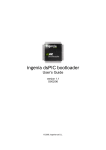
DH-2 De-Hisser
Digital Audio Restoration System
SERIES 2
Digital
Over
Power
Over
0dB
0dB
-10
-10
-20
-20
-40
48kHz
4
0
Input Level
interstage
Phistersvej 31, 2900 Hellerup, Danmark
Telefon 3946 0000, fax 3946 0040
www.interstage.dk
8
10
12
Output Attenuation
Page
Pre/Post
Enter
Pre
Post
6
2
Bypass
Bypass
-40
Level
Phones
44.1kHz
CEDAR
CEDAR Audio Ltd
A member of the
Association of Professional Recording Services
Contrast
De-Hisser DH 2
SERIES 2
OWNER'S MANUAL
© 1996 CEDAR Audio Ltd
- pro audio with a smile
DH-2: Rev.01 Ver.1.00
November 30, 2005
Page - 1
TABLE OF CONTENTS
INTRODUCTION.........................................................................................................................................................3
THE BACKGROUND TO CEDAR NOISE REMOVAL .....................................................................................4
SAFETY INSTRUCTIONS........................................................................................................................................8
SET UP .......................................................................................................................................................................10
CONNECTIONS........................................................................................................................................................11
SAMPLE INSTALLATION IDEAS .......................................................................................................................14
A GUIDE TO RESTORATION PROCESSING..................................................................................................15
LOCATION AND FUNCTION OF FRONT PANEL INDICATORS AND CONTROLS ............................17
QUICK TOUR ............................................................................................................................................................19
WARMSTART AND COLDSTART ......................................................................................................................20
OPERATING THE CEDAR DH-2 .........................................................................................................................21
TUTORIAL .................................................................................................................................................................36
THE TUTORIAL TAPE............................................................................................................................................39
REMOTE CONTROL PROTOCOLS ...................................................................................................................40
SELF TEST MODE ..................................................................................................................................................43
DH-2: Rev.01 Ver.1.00
November 30, 2005
Page - 2
INTRODUCTION
Thank you for purchasing the CEDAR DH-2 De-Hisser Module. This is the world's
most advanced dedicated single-ended noise removal unit, and offers processing
power and performance that could only previously be obtained using digital signal
processors (DSPs) installed in desk-top (or larger) computer systems such as
CEDAR for Windows. The De-Hisser is designed for professional use, although it will
work perfectly well in a domestic environment, and its features include the following:
•
Revolutionary noise removal algorithms
•
No need for a “Spectral Fingerprint”
•
The latest 'SERIES-2' CEDAR hardware
•
Digital Audio interfaces conforming to the AES/EBU and SPDIF standards
•
24-bit input and output resolution when using AES/EBU interfaces
•
Three sample rates supported on digital inputs: 32kHz, 44.1kHz and 48kHz
•
Two sample rates supported on analogue inputs: 44.1kHz and 48kHz
•
Balanced analogue inputs and outputs for connection to professional
analogue equipment
•
ADC and DAC converters using the latest 64x over-sampling ∆-∑ (DeltaSigma) technology
•
>103dB dynamic range A/D and >93dB dynamic range D/A
•
Mountable in a 19" EIA rack
•
Remote control via MIDI and RS232 interfaces
•
SMPTE/EBU timecode capabilities via optional upgrade
•
Input and output LED bar-graph VU meters
•
Twin 40-bit floating point DSP processors delivering 50MFlops to handle the
most complex audio processing requirements
•
High levels of artificial intelligence designed into the DH-2 program algorithms
making it extremely simple to use
DH-2: Rev.01 Ver.1.00
November 30, 2005
Page - 3
THE BACKGROUND TO CEDAR NOISE REMOVAL
Cheap digital audio (i.e. CD) has made discerning listeners quite intolerant of the
noises and distortions present in analogue audio signals. After all, in a perfect digital
world there are no clicks, crackle, pops, buzzes or hums, and no hiss - so it's a
shame that we live in a far from perfect world. Even today, the vast majority of
mixing desks still have all-analogue signal paths, so most DDD-classified CDs are
still mastered through numerous analogue stages. And 'vintage' (i.e. pre-1980s’)
recordings are by definition re-mastered from analogue disks and master tapes
which inevitably suffer from at least one of the degradations listed above. So
recording engineers are turning more and more to the technologies that reduce the
noise added in the signal path, or are capable of removing it from the final recording.
Before proceeding any further, perhaps it would be best to describe what we mean
by the term 'broadband' noise, defining it to be a random effect which adds (or
subtracts) a random amplitude at all times to (or from) all frequencies within the
audio spectrum. Thus, we do not include artefacts of very limited duration such as
intermittent electrical clicks or microphone 'grounding' which may be corrected by
quite different methods to those described below.
Next, let's dispel any illusions regarding Dolby, dbx, and similar noise reduction
systems. These are dual-ended processes designed to minimise the accumulation of
any extra noise added by the limitations of analogue recording tape. (Dual-ended
processes are commonly called encode/decode systems because the recording
process 'encodes', and the playback process 'decodes', the signal.) None of these
processes enable you to remove noise from within a signal that already contains it they simply stop you adding too much more when you commit that signal to tape and
then play it back again. Perversely, they therefore help your tape deck to accurately
record, and then faithfully reproduce, any noise contained in the original signal. So,
what you need is a 'single-ended' process that removes noise from your signals prior
to committing them to tape, or at the very least, improves the signal to noise (S/N)
ratio without affecting the signal adversely. Which brings us neatly to the volume
control... stunningly effective at removing noise, it does nothing to improve the S/N
ratio, and has an all-too-noticeable side-effect. No noise, No signal.
Since broadband noise is most intrusive at high frequencies, where the masking
effect of loud sounds is least present, the first stage in our evolutionary tale of noise
removal is the simple low-pass filter. Less damaging than the volume control which
removes the signal altogether, this only removes a proportion of any signal present
above its cut-off frequency, fc. Unfortunately, if, at the given frequency, you reduce
the amplitude of the noise content of your recording by, say, 6dB, you also reduce
the genuine signal at this frequency by the same amount. This may be acceptable if
the recording has little or no high frequency content, but natural sounds and modern
electronic instruments have significant components up to and beyond the limits of
human hearing. Consequently, the low-pass filter will only be successful in
processing your antique collection of '78's, and even then only at a cost.
But this gives us a hint as to how a more effective single-ended noise reduction
system could be designed: perhaps a device could be built which removes the high
frequencies when there is no signal present, but leaves them untouched when the
noise is being masked by genuine high frequencies? It's a Dynamic Filter (so called
DH-2: Rev.01 Ver.1.00
November 30, 2005
Page - 4
because fc moves dynamically according to the signal content). But such devices
are limited: for one thing, they can only remove the noise which exists above fc,
which is itself an inaccurate representation of the highest frequencies contained in
the genuine signal at any given time. Secondly, and in common with the simple lowpass filter, they have roll-offs typically of the order -12dB/octave or -6dB/octave, so
they always allow some high frequencies through. And thirdly, even though the filters
are designed to track the signal very quickly, they cannot respond instantaneously,
so they tend to round off fast transients. And, because their raison d'être is to reduce
the signal bandwidth they also tend to dull the genuine signal quite perceptibly. So to
summarise dynamic filters: if you're not compromising the signal you may not be
removing as much noise as you wish, and if you're removing all the noise you're
probably damaging the genuine signal.
Perhaps an alternative approach could give better results? Instead of altering the
frequency response of the signal to reduce the noise content, how about changing
the overall signal level in some way? This isn't such a strange idea. Consider: if
noise of a relatively constant amplitude is always present in a signal then, if the total
signal amplitude drops down to the noise level, we can assume that no genuine
signal is present. While there are many flaws in this argument (largely to do with the
statistical nature of broadband noise) it suggests a device which will eliminate some
of the noise: a Noise Gate. This detects when the signal drops below a certain
'threshold' set by the user and then cuts off the signal entirely. There are many
enhancements to the Gate idea, such as variable attack and release times, and
hysteresis (all added to limit the occurrence of damaging side-effects) but the
principle always remains the same: if the total signal drops below the amplitude
threshold, the gate shuts off the signal.
Just as the filter can be improved by making it dynamic, so can the gate. Such a
device is called an Expander. The Expander still has a threshold control, but unlike
the gate, the Expander applies a progressive gain reduction, the amount of which is
determined by the settings selected by the user. For example, if a signal drops 3dB
below the threshold, the Expander may reduce the signal volume by 6dB, 12dB, or
any other figure, depending upon the expansion ratio. Unfortunately, the subjective
difference between the noise gate and the expander is small and, though they sound
great in theory, they don't sound so great in reality. Being time domain processes,
they have advantages and disadvantages when compared to frequency domain
filtering, but only sound different, not better. In particular, they have the distinct
advantage that, when active, they remove all the noise, but once inactive (or ‘open’)
no noise is removed. And if you adjust the threshold so that noise can only come
through when the signal is loud enough to mask it, you lose the ability to include
quiet passages in your recordings.
Commercial noise reduction units now feature a combination of dynamic filtering,
expansion, and even compression and excitation - effects which have been included
in an attempt to obscure some of the undesirable side-effects of the noise reduction
processes. But these are only partially successful, and you still can't master full
bandwidth CDs or film soundtracks with them. The results simply aren't good
enough.
Whenever a single-band expander encounters a signal with amplitude below its
threshold, it further reduces the volume. But what if there is still a significant signal at
DH-2: Rev.01 Ver.1.00
November 30, 2005
Page - 5
(say) 3kHz, but very little elsewhere in the frequency spectrum? The single-band
expander has no way of discerning the genuine signal, and shuts this out at the
same time as all other frequencies. A multi-band device separates the audio
spectrum into a number of bands, and treats each of these as an individual signal.
This form of noise reduction has evolved from simple analogue units onto Digital
Audio Workstations which can incorporate high power DSPs capable of splitting the
audio spectrum into multiple bands and applying expansion to each of these in the
digital domain. But multi-band units are still unable to distinguish accurately between
genuine signal and noise. They still act upon the inaccurate assumption that, if the
total signal level approaches its noise floor, all that is present is broadband noise.
Consequently, even the most sophisticated downwards expanders and dynamic
filters remove some of the genuine signal. Furthermore, the poor band separation
filters (typically of the order -6dB/oct or -12dB/oct) severely limit performance. The
consequences of these problems are well understood and largely unavoidable: loss
of high frequencies, loss of ambience, and degradation of hard transients.
All the methods so far described use filters, gain controls, or a combination of both to
achieve their results. Whether implemented in either the analogue or digital domain,
all such filters and gain controls are 'ratio' devices - that is, if (at any given
frequency) you remove half the power of the noise, you remove half the power of the
signal; if you remove 3/4 of the noise, you remove 3/4 of the signal... and so on.
Consider now a signal that has, at a given frequency, 100 units of 'volume' on some
arbitrary scale. By measuring the noise content of that signal during an otherwise
silent passage, you can determine that there are, say, 20 units of noise present at
that frequency. It should be possible to remove this noise by removing 20% of the
signal. But what if, a moment later, the total ‘volume' of the signal drops to 40 units?
An analogue filter, removing 20% of the signal in the same manner, will only remove
8 units of the 20. On the other hand, a subtractive filter (which is practical only in the
digital domain) will still remove the full 20 units, equivalent to a filter reduction of
50%. This is, of course, what we want, because the noise at this moment represents
50% of the total signal amplitude. So now we arrive at the most sophisticated noise
removal technology yet implemented in a commercial sense: computerised spectral
subtraction.
The concept of Spectral Subtraction becomes useful when a DSP is used to split an
audio signal into hundreds of bands. You can then be very precise about how much
noise you remove, subtracting a lot at (say) 8kHz, while leaving 8.1kHz virtually
untouched. But if this sounds to good to be true, it is. The noise spectrum (the sonic
'fingerprint') can only be accurately measured if there is an otherwise silent passage
within the music. If the fingerprint is not accurate the amounts subtracted will be
wrong, leading to unpleasant side-effects. And, worse still, many tracks are 'close
edited', making it impossible to obtain any such fingerprint. But let's assume that you
have obtained a perfect fingerprint. You might expect to produce a good restoration,
with large amounts of noise removed and few or no side-effects. Yet experience
shows that all attempts to implement spectral subtraction in this unmodified form
produce both (i) unacceptable artefacts, and (ii) unusably dry and dull results. This
is, in part, because the fingerprint is merely a snapshot of the random noise,
accurate only at the instant at which it is taken. Because the noise content is
constantly changing, an unmodified subtractive algorithm will be deriving its result
from inappropriate data. Garbage in, garbage out.
DH-2: Rev.01 Ver.1.00
November 30, 2005
Page - 6
These pitfalls have prompted much commercial and academic research, and many
companies and independent researchers have investigated enhancements designed
to overcome them. CEDAR Audio’s developments are embodied in its product,
‘HISS2’, which incorporates an algorithm that updates the noise fingerprint every
1,000 samples. This allows the system to track variations in the noise content. It also
features algorithms that prevent the compression of incoming transients, and that
distinguish between true noise and, for example, reverberation tails of the genuine
signal. These and other features avoid many of the pitfalls of simple spectral
subtraction, and allow users to remove noise without undue damage to the genuine
signal contained within the source.
But this system still requires a noise fingerprint, whether captured from the signal or
created by arbitrary means. Consequently, the user-interface is complex, and the
system cannot be implemented in a stand-alone box. The greatest simplification of
this interface requires an algorithm capable of autonomous determination of the
noise content. Such methods are the subject of much on-going research although,
as yet, only two have been proved sufficiently accurate to be incorporated within
commercial products. Developed by CEDAR, these algorithms make possible a
stand-alone module that dispenses with the user-derived noise fingerprint. The
algorithm will itself analyse the noise content of the signal and apply an automated
noise reduction process. Further development of this process has led to an
enhanced computer-based software module called Dehiss2, which may be found in
the CEDAR for Windows™ suite of audio restoration products, as well as the latest
DH-2 De-Hisser.
Dolby and dbx are trademarks of their respective manufacturers.
DH-2: Rev.01 Ver.1.00
November 30, 2005
Page - 7
SAFETY INSTRUCTIONS
CAUTION:
1.
Read all of these instructions
All safety and operating instructions should be read before the DH-2 is
operated.
2.
Save these instructions for future reference.
3.
Follow all warnings and instructions.
4.
Water and Moisture
The DH-2 should not be used near water, and must not be exposed to rain or
moisture. If the DH-2 is brought directly from a cold environment into a warm
one, moisture may condense inside the unit. This, in itself, will not damage
the DH-2, but may cause hazardous electrical shorting to occur. This could
severely damage the DH-2, and even cause danger to life. ALWAYS allow
time for the DH-2 to naturally reach ambient temperatures before connecting
the mains power.
5.
Mounting
The DH-2 should be carefully mounted in a 19" EIA rack, or placed on a flat,
stable surface. If it is used on a cart or free stand, care should be taken when
it is moved: uneven surfaces or excessive force may cause cart and DH-2 to
overturn. Do not position the DH-2 in a place subject to strong sunlight,
excessive dust, mechanical vibration or periodic shocks.
6.
Wall or Ceiling Mounting
The DH-2 has not been designed for mounting directly to walls or ceilings.
7.
Ventilation
Good air circulation is essential to prevent internal heat build-up within the
DH-2. The DH-2 should be situated so that its position does not interfere with
proper ventilation. The DH-2 should not be placed in any situation which
impedes the flow of air through the vents at the front and rear. Do not place
the DH-2 on a soft surface.
8.
External Heat Sources
The DH-2 should be installed away from significant heat sources such as
radiators, and (if possible) away from other audio devices such as amplifiers
that produce large amounts of heat. Installation in racks with devices such as
signal processors or tape machines should not be a problem.
9.
Power Sources
The DH-2 features an auto-switching power supply which will work safely on
any mains supply in the ranges 95v/130v and 190v/260v, 50Hz or 60Hz AC
only.
You should never attempt to modify or adjust the internal power supply
in any way. It contains no user serviceable parts.
DH-2: Rev.01 Ver.1.00
November 30, 2005
Page - 8
10.
Grounding or Polarisation
The DH-2 should always be grounded (or 'earthed').
11.
Power Cord Protection
Power connectors should be routed so that they will not be walked on or
pinched.
12.
Extended Periods of Non-Use
The DH-2 is not disconnected from the mains power as long as it is
connected to the wall outlet, even if the unit itself has been switched off.
Therefore, if the DH-2 is not to be used for an extended period of time, unplug
the unit from the wall. Pull the connector out by the plug, never by the cord
itself.
13.
Cleaning
Clean only with a dry cloth. NEVER use liquid cleaners such as alcohol or
benzene on the DH-2. NEVER use abrasive pads on the DH-2.
14.
Damage Requiring Service
The DH-2 should be returned to qualified service personnel when:
•
objects have fallen into the unit
•
liquid has been spilled into the unit
•
the unit has been exposed to rain
•
the unit fails to function or appears to operate abnormally
•
the unit has been dropped, or the case damaged.
15.
Servicing
The user should not attempt to service the DH-2 beyond the instructions
contained in the User's Manual. All other servicing should be referred to
qualified service personnel.
DH-2: Rev.01 Ver.1.00
November 30, 2005
Page - 9
SET UP
1.
UNPACKING AND INSPECTION
Be careful not to damage the DH-2 during unpacking. Save the carton and all
packing materials since you may need them to transport the DH-2 in the
future.
In addition to the DH-2 and the packaging, the carton should contain the
following:
•
•
•
•
2.
mains connection lead
this manual
blanking plates which may be used to replace the rack-mount ears
DH-2 Tutorial DAT
INSTALLATION SITE
The DH-2 may be used in most areas, but to maintain reliability and prolong
operating life observe the following environmental considerations:
3.
•
Nominal temperature should be maintained between 5˚ and 35˚
Centigrade (41˚ and 95˚ Fahrenheit).
•
Relative humidity should be in the range 30% to 60% non-condensing.
•
Strong magnetic fields should not exist nearby.
RACK MOUNTING
The DH-2 can be mounted in a standard 19" EIA rack.
4.
FREE STANDING USE
The DH-2 can be used as a free-standing unit. The rack-mount ears may then
be replaced by the blanking plates if desired.
To replace the ears with the blanking plates:
•
Unscrew the three bolts which attach each ear to the chassis of the
DH-2.
•
Attach the blanking plates using the same retaining bolts. Do not overtighten these bolts as doing so may cause damage to the DH-2.
DH-2: Rev.01 Ver.1.00
November 30, 2005
Page - 10
CONNECTIONS
The DH-2 may be connected to most of the professional audio equipment currently
available. Three types of audio input and output are provided (one analogue and two
digital) and these will satisfy most users' interconnection requirements. Full
descriptions of these connectors will be found later in the manual.
1.
2.
BEFORE CONNECTION
•
To prevent problems and possible equipment damage, turn off the
power to all equipment before making connections.
•
Be sure to insert plugs firmly into sockets. Loose connections may
cause hum and noise.
•
When unplugging any lead, do so by grasping the plug, not the lead.
POWER CONNECTIONS
Ensure that the DH-2 is switched OFF before inserting the mains lead.
NOTE: Users with 2-pin mains supplies:
When the DH-2 is connected to other audio components, the AC hum of the
unit may be increased or decreased by reversing the direction of the power
connector in the socket. Check that the cord is in the favourable position ('inphase') with respect to other audio devices in the chain. This will ensure that
the best sound quality is obtained from your DH-2.
For further information on grounding and polarity consult a person familiar
with studio grounding techniques.
3.
SIGNAL LEAD CONNECTIONS
Refer to the Rear Panel diagram:
The DH-2 offers three audio connection standards: one analogue and two
digital. These are:
•
•
•
balanced analogue audio I/O
digital SPDIF format audio data
digital AES/EBU format audio data
Note that the DH-2 always passes its output to all three signal outputs
irrespective of the input used, but that the digital data will only be formatted
for either AES/EBU or SPDIF, as defined by the user parameters.
DH-2: Rev.01 Ver.1.00
November 30, 2005
Page - 11
(i)
Balanced analogue audio I/O (Pin 2 - 'hot')
This standard is used in professional audio equipment. Connect the
output from your source to the balanced analogue inputs of the DH-2
using standard XLR plugs. You will require two such connections: one
for each channel.
The balanced audio output may be used to connect the DH-2 directly
to audio equipment such as mixing desks and professional recorders
featuring balanced XLR inputs and outputs.
(ii)
Digital SPDIF format audio data
The SPDIF format is used by domestic and semi-professional digital
audio devices such as DAT machines, some ADCs, and some CD
players. Both audio channels are carried along a single cable, so you
may connect the SPDIF output from your source to the SPDIF input of
the DH-2 using a single cable terminated with RCA (or 'phono') plugs.
The SPDIF output of the DH-2 may be connected to the SPDIF input of
your recording device or external DAC.
(iii)
Digital AES/EBU format audio data
The digital AES/EBU format is used by professional digital audio
devices including mastering systems, DASH recorders, and high
quality ADCs & DACs. Both channels of audio are carried along a
single cable, so you may connect the AES/EBU output from your
source to the AES/EBU input of the DH-2 using a single cable
terminated with XLR plugs.
The AES/EBU output of the DH-2 may be connected to the AES/EBU
input of your digital mixer, recording device or external DAC.
24-bit Digital data resolution:
The DH-2 features 24-bit input and output resolution whenever the
AES/EBU digital input and output are utilised.
Dithering:
The DH-2 also features TPDF (Triangular Probability Density Function)
dithering. This is applied to the digital data when the SPDIF output
format is selected. Dithering is always applied to the data presented to
the DACs.
Note: In order to fully comply with EMC regulations, this unit should be
connected via its AES/EBU and/or analogue connectors. Metal-shelled
XLR connectors should be used. We recommend using a good quality
‘starquad’ cable, with three cores connected to pins 1, 2 & 3. The
shield of the cable should be connected, at both ends, to the outer
shell of the connector.
DH-2: Rev.01 Ver.1.00
November 30, 2005
Page - 12
4.
OTHER CONNECTIONS
(i)
SMPTE/EBU
The DH-2 has been designed to host an optional SMPTE/EBU
interface offering LTC and VITC protocols. The standard DH-2 does
not support timecode and these connectors are not present.
(ii)
MIDI IN/OUT/THRU
The operation of the DH-2 may be controlled using the Musical
Instrument Digital Interface (MIDI). Refer to the chapter on Remote
Control Protocols for further instructions.
(iii)
RS232
The DH-2 may be controlled using the standard RS232 serial
communications protocol. Refer to the chapter on Remote Control
Protocols for further instructions.
DH-2: Rev.01 Ver.1.00
November 30, 2005
Page - 13
SAMPLE INSTALLATION IDEAS
analogue or
digital in
line out
TURNTABLE OR
TAPE MACHINE
analogue or
digital in
analogue or
digital out
DH-2
RECORDER
line in
AMP
1.
DH-2 used in-line for transcription or broadcast purposes.
analogue or
digital in
line out
SOURCE
analogue or
digital out
MIXER
effects send
line in
analogue or
digital in
RECORDER
effects return
line in
line out
AMP
DH-2
2.
DH-2 used on the effects loop within a studio environment.
line out
SOURCE
analogue or
digital in
analogue or
digital out
DH-2
analogue or
digital in
analogue or
digital out
analogue or
digital in
CEDAR
RECORDER
or other workstation/editor
line in
AMP
3.
DH-2 used in-line prior to an editor or audio workstation.
DH-2: Rev.01 Ver.1.00
November 30, 2005
Page - 14
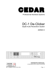
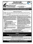
A GUIDE TO RESTORATION PROCESSING
Contrary to ‘common sense’, the order in which restoration processes are carried out
makes a great deal of difference to the quality of the final result. Consequently, there
is one ‘right way’ and many ‘wrong ways’ to restore your material.
Following these guidelines will help you to achieve the best results on most material:
•
De-Clicking (De-Scratching) should ALWAYS be carried out first. This is
because:
i
Large clicks make it difficult for the De-Crackling process to identify
and remove the tiny clicks and crackles that constitute surface noise,
buzz, and other such problems.
ii
All clicks and scratches are, in effect, tightly defined packets of white
noise. If clicks are presented to any of the CEDAR De-Hiss products
(HISS-1, HISS-2, Auto De-Hiss, Dehiss, Dehiss2, the DH-1 or the DH2) they confuse the processes, and create unmusical side-effects. In
addition, De-Hissing at this stage will make it almost impossible to
identify and remove clicks and scratches at a later time.
•
De-Crackling should be the next process because even small crackles can
cause the same problems as in (ii) above.
•
Azimuth Correction can be carried out either before or after De-Hissing, but
experience shows that best results are obtained using the AZ-1 or Phase-EX
module before De-Hiss.
•
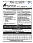
Finally, apply the DH-2.
Note: If you have the full range of CEDAR restoration modules they should be
connected as shown in the diagram overleaf. Please note that, to maintain the
maximum fidelity and remove and possible sources of degradation between
processes, connections between modules should be by AES/EBU (24-bit)
format.
DH-2: Rev.01 Ver.1.00
November 30, 2005
Page - 15
Digital
Over
Power
Over
0dB
0dB
-10
-10
-20
-20
-40
44.1kHz
48kHz
Post
6
8
4
12
0
Phones
Input Level
A member of the
Association of Professional Recording Services
Output Attenuation
Pre/Post
Enter
CEDAR
CEDAR Audio Ltd
10
2
Page
Pre
-40
Level
Bypass
Bypass
De-Clicker DC 1
SERIES 2
Contrast
Firstly, De-Click your material
Digital
Over
Power
Over
0dB
0dB
-10
-10
-20
-20
-40
44.1kHz
48kHz
Post
6
8
4
2
12
0
Phones
Input Level
A member of the
Association of Professional Recording Services
Output Attenuation
Pre/Post
Enter
CEDAR
CEDAR Audio Ltd
10
Page
Pre
-40
Level
Bypass
Bypass
De-Crackler CR 1
SERIES 2
Contrast
Next, remove crackle and buzz, and reduce distortion if appropriate
Digital
Over
Power
Over
0dB
0dB
-10
-10
-20
-20
-40
44.1kHz
48kHz
Post
6
4
8
0
12
Input Level
A member of the
Association of Professional Recording Services
Output Attenuation
Pre/Post
Enter
CEDAR
CEDAR Audio Ltd
10
2
Phones
Page
Pre
-40
Level
Bypass
Bypass
Azimuth Corrector AZ 1
SERIES 2
Contrast
Then apply Azimuth Correction to material with phase and balance problems
Digital
Over
Power
Over
0dB
0dB
-10
-10
-20
-20
-40
48kHz
4
0
Input Level
8
10
12
Output Attenuation
Page
Pre/Post
Enter
Pre
Post
6
2
Bypass
Bypass
-40
Level
Phones
44.1kHz
CEDAR
CEDAR Audio Ltd
A member of the
Association of Professional Recording Services
Contrast
De-Hisser DH 2
SERIES 2
Finally, apply noise reduction.
DH-2: Rev.01 Ver.1.00
November 30, 2005
Page - 16
LOCATION AND FUNCTION OF FRONT PANEL
INDICATORS AND CONTROLS
Refer to the Front Panel diagram:
1.
Power Switch
2.
Input Signal Meters (Left and Right)
Digital signal meters display the peak value of the selected input in dB0s.
The 'Over' indicators will light if the input signal remains at full scale for four or
more consecutive samples.
3.
Output Signal Meters (Left and Right)
Calibrated signal meters display the peak value of all output signals.
The 'Over' indicators will light if the output signal remains at full scale for four
or more consecutive samples.
4.
LCD Screen
Provides you with a variety of information and messages, keeping you aware
of what is currently happening in the DH-2.
All the control screens of the DH-2 are displayed on the LCD screen. Please
refer to the following chapters for full instructions.
5.
Status Indicators
Indicate the status of the analogue and digital inputs, and whether the DH-2 is
in idle or processing modes.
Also indicate the possible causes should the unit fail to function.
6.
Dedicated Function Keys.
Certain functions are fundamental to operating the DH-2, and these are
controlled by the dedicated function keys: Bypass, Page, Pre/Post, and Enter.
7.
α-dial (Spinwheel)
The α-dial enables you to increase and decrease control values. Please refer
to the following chapters for full instructions.
8.
Headphone Socket
For use with stereo headphones only. Accepts a standard 1/4" stereo jack
plug. DO NOT use 2-conductor mono headphones with the DH-2.
9.
Headphone Level Control
Use this to adjust for a satisfactory listening level. This level control will not
alter the signal level at any of the rear panel outputs.
DH-2: Rev.01 Ver.1.00
November 30, 2005
Page - 17
10.
Input Level Control
This control acts upon the analogue inputs only. Use it to adjust the volume of
incoming analogue signals to the desired level. A level of approximately 0 to 3dB (as shown on the Input Signal Meters) will offer best results.
The Input Level Control may be physically bypassed internally to obtain the
best possible signal to noise ratio (S/N) from the ADCs. This work must be
carried out by qualified service personnel, so please refer to your authorised
dealer or directly to CEDAR Audio to have this modification performed.
11.
Output Attenuation Control
A digital gain control with range 0 to -10dB in 1dB steps.
12.
Function Keys
Use along with the LCD screen. Please refer to the following chapters for full
instructions.
13.
Contrast Control
The LCD screen may be adjusted for optimum visibility. Use a fine
screwdriver to make such adjustments.
DH-2: Rev.01 Ver.1.00
November 30, 2005
Page - 18
QUICK TOUR
If you are impatient to hear some immediate results using your DH-2 the following
instructions should have you up and running within a few minutes:
1.
READ THE SAFETY INSTRUCTIONS.
2.
Connect the DH-2 to the mains supply.
3.
Connect your input and output devices to the DH-2 using the appropriate
input and output sockets. (If in doubt, please refer to the section
CONNECTING THE DH-2 and the manuals of your other equipment).
4.
Referring to the front panel diagram, hold down the function key F1 and
switch on the DH-2.
5(i)
If you are using analogue inputs press PAGE once. Press B (function key F2)
to select 'analogue'. Then press PAGE twice more to return to the Control
Page.
5(ii)
If you are using digital inputs from a consumer format machine such as a
domestic DAT recorder press PAGE once, then press B twice to select
'SPDIF'. If you are outputting to a consumer format machine such as a lowcost DAT recorder press A (function key F1) to select SPDIF format.
Press PAGE twice to return to the Control Page
Note: The DH-2 defaults to AES/EBU PROFESSIONAL format, so skip both
instructions 5(i) and 5(ii) if your DH-2 is connected via its AES/EBU
input and output.
6.
Play your material through the DH-2.
7.
Press function key F2 to select the LEVEL control, and use the α-dial to vary
LEVEL between 0.00 and 99.00. Provided that the material you are playing
contains hiss you will, at some point within the scale, hear it disappear.
8.
With ATTEN set to -40.0 and BRT set to 0.00 you will almost certainly hear
side-effects while you adjust LEVEL. Experiment with ATTEN and BRT to
hear how these affect the output. Please refer to the TUTORIAL section for a
full explanation of these controls, how they interact, and how to get the best
results from them.
This section should have whetted your appetite, so you should now proceed to the
rest of the manual.
DH-2: Rev.01 Ver.1.00
November 30, 2005
Page - 19
WARMSTART AND COLDSTART
The DH-2 features Warmstart and Coldstart options. Warmstart has been added so
that the unit can be configured once, and these parameters are then automatically
recalled on every power-up. This is ideal for applications where time-consuming setups at the start of each session are not practical.
Coldstart
If the DH-2 has not been used for some time the system will automatically Coldstart.
This process initialises all parameters to their factory default values, and after a few
seconds the DH-2 will automatically enter at Page 1.
On start-up the message 'Coldstart' will be displayed at the top right of the start-up
screen on the LCD display. The screen will then enter PAGE 1, which will show the
default parameters:
The default values are:
LEVEL
ATTEN
BRT
=
=
=
0.00
-40.0
0.00
Other default values are:
Digital Output
Input Source
Receiver Error Level
MIDI
Bypass
A to D frequency
Pre/Post
=
=
=
=
=
=
=
AES/EBU
AES/EBU
1 - Lock
Channel 1
OFF
44.1kHz
Post
Warmstart
The DH-2 remembers the latest parameters used, and the page that was active at
the time that the system was last switched off.
On start-up the DH-2 will display the message 'Warmstart' on the screen, and after a
few seconds will re-enter at the appropriate page, with all user parameters set to
their previous values.
User Coldstart
If you wish to force the DH-2 to Coldstart, hold down Function Key F1 while
switching on the system. Release F1 when the message Coldstart is seen on the
LCD display.
Note: In common with all other digital devices, and irrespective of whether you are
Warmstarting or Coldstarting the DH-2, you should always allow a few
seconds between switching the unit off, and switching it on again.
DH-2: Rev.01 Ver.1.00
November 30, 2005
Page - 20
OPERATING THE CEDAR DH-2
1.
DEDICATED CONTROLS:
The DH-2 features a number of dedicated controls to speed operation. These are
now explained in turn:
Bypass
You may wish to bypass completely the operation of the DH-2. Press BYPASS to do
this. The current status will be indicated on the Status LED. The Bypass does not
'hard-wire' the input to the output. Analogue signals still pass through the A/D and
D/A stages.
Notes:
•
There is a delay of approximately 1.3mS in any analogue-to-analogue
signal passed through the DH-2 in Bypass mode.
•
There is a delay of approximately 0.1mS in any digital-to-digital signal
passed through the DH-2 in Bypass mode.
•
All delays are 'group delays' (i.e. are constant at all frequencies) and
are measured at a sample rate of 44.1kHz.
Page
Use this Function Key to move between Pages.
Pre/Post
It will often be useful to compare the original signal with the post-processing output
of the DH-2. The current status will be indicated on the Status LEDs.
Enter
The ENTER Key has three functions: as a LOCK-OUT key, preventing accidental
changing of parameters; as a CLEAR key, resetting error messages, and as a MIDI
DUMP command.
These first two functions are, of course, context sensitive, and the key's action will
be appropriate to the page displayed (see below). The MIDI DUMP will be initiated
every time that the ENTER key is pressed, regardless of context.
Input Level
This control acts upon the analogue inputs only. Use it to adjust the volume of
incoming signals to the desired level. We recommend a peak level of approximately
0 to -3dB as shown on the Input Signal Meters.
DH-2: Rev.01 Ver.1.00
November 30, 2005
Page - 21
Output Attenuation
Avoid clipping using the Output Attenuation Control. This is not a compressor or
limiter, and acts purely as a digital gain control with variable gain from 0dB to -10dB
in 1dB steps.
DH-2: Rev.01 Ver.1.00
November 30, 2005
Page - 22
OPERATING THE CEDAR DH-2
2.
PAGES:
The DH-2 has three 'pages' which control all aspects of its operation. Each page is
selected by pressing the dedicated PAGE function key, displayed on the LCD
screen, and may be controlled using the Function Keys and the α-dial.
Note: There is a fourth, normally hidden, page called the Status Page. This is not
accessed using the standard 'Page' function, and will be discussed separately
in the section describing Error Levels.
PAGE 1:
CONTROL PAGE
If necessary, access this page by pressing the Dedicated Function Key PAGE until
the Control Page appears.
There are five controls in the Control page. These correspond to the five 'soft-keys'
and are to be found directly above each of them as follows:
F1
F2
F3
F4
F5
•
•
•
•
•
Stereo Ganging/Left/Right Control
LEVEL Control
ATTEN (Attenuation) Control
BRT (Brightness) Control
Clear
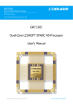
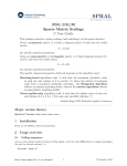
The controls, and therefore the DH-2 itself, act in the following manner:
Brightness
Level
Tonal
Analysis
Transient
Analysis
Ambience
Analysis
Gain
Structure
Noise
Reduction
Input
Input Level
Meters
Attenuation
Attenuation
Control
Output
Output Level
Meters
Figure 1: The DH-2 process overview, and the stages at which the CONTROL
PAGE controls modify the signal.
DH-2: Rev.01 Ver.1.00
November 30, 2005
Page - 23
You can optimise the beneficial effect of the DH-2 by setting each of these controls
appropriately. They are now described in turn:
DH-2: Rev.01 Ver.1.00
November 30, 2005
Page - 24
LEVEL:
The LEVEL control is used to give the DH-2 algorithm a rough idea of the amount of
noise present in any given signal. This is the most sensitive and important control on
the DH-2, and incorrect use will result in sub-standard results and/or unwanted sideeffects.
•
LEVEL = too low
The DH-2 will not remove all the noise and (especially at high brightness
levels) will generate an artefact from residual noise pulses let through by the
process. This is often described as 'twittering'.
•
LEVEL = too high
Some low-level signal will be treated as noise and will be attenuated. This
results in compression and an artefact called 'glugging'.
LEVEL may be adjusted as follows:
•
Press F2 to select the LEVEL control. A box will appear around the
numerical display to indicate that the control is selected.
•
Rotate the -dial clockwise and/or anti-clockwise to alter LEVEL in
steps of 0.01.
•
Rotating the -dial slowly will result in delicate adjustments, whilst
faster rotation will increase the rate at which LEVEL changes.
ATTEN:
ATTEN sets a maximum limit on the amount of noise that the DH-2 will remove at
any time at any given frequency. It is quantified in dBs.
The side-effects introduced by inappropriate use of LEVEL are exaggerated when
the DH-2 is asked to remove too much noise. Correct use of ATTEN will ensure that
none of the side-effects caused by over- or under- processing are heard in the output
signal. In cases of difficulty, you can often trade off the side-effects against the
amount of hiss reduction.
ATTEN may be adjusted as follows:
•
Press F3 to select the ATTEN control. A box will appear around the
numerical display to indicate that the control is selected.
•
Rotate the -dial clockwise and/or anti-clockwise to alter ATTEN in
steps of 0.1.
•
Rotating the -dial slowly will result in delicate adjustments, whilst
faster rotation will increase the rate at which ATTEN changes.
DH-2: Rev.01 Ver.1.00
November 30, 2005
Page - 25
BRT:
Brightness controls how the DH-2 compromises between the various side-effects. Its
theoretical optimum is 50. However, in practice, the optimum setting for Brightness
depends upon the nature of the signal and the hiss contained within it. It may also be
influenced by any compromises you wish to make in order to achieve certain results.
•
Brightness = too low
At lower brightness settings the DH-2 will favour consistent compression
instead of more unmusical or artificial-sounding artefacts. Generally, a low
brightness is appropriate if you want to remove a lot of noise.
•
Brightness = too high
At higher brightness settings the DH-2 will minimise the compression of any
low-level signals, but becomes susceptible to twitters and noise pumping. A
high brightness is suitable when you wish to remove a small amount of noise .
Note: You will find that the threshold and the brightness interact. Higher
brightnesses will require slightly higher thresholds than lower brightnesses.
BRT may be adjusted as follows:
•
Press F4 to select the BRT control. A box will appear around the
numerical display to indicate that the control is selected.
•
Rotate the -dial clockwise and/or anti-clockwise to alter BRT in steps
of 0.01.
•
Rotating the -dial slowly will result in delicate adjustments, whilst
faster rotation will increase the rate at which BRT changes.
Ganging:
The DH-2 may be used to process stereo material. The left and right channels of
such material can be entirely independent and exhibit quite different noise
characteristics. The “Ganging” control allows you to select which channel(s) are
affected when you adjust LEVEL, ATTEN, and BRT.
The Ganging control has three modes:
Ganged:
Adjusting the controls affects the left and right channels
identically unless such adjustment would move a channel
beyond the limits of the scale. In this mode, the numeric
readouts beneath the control bars displays the average value of
the left and right channels’ values.
Left:
Only the left channel is affected, and the numeric readouts
beneath the control bars displays the left channel’s values.
DH-2: Rev.01 Ver.1.00
November 30, 2005
Page - 26
Right:
Only the right channel is affected, and the numeric readouts
beneath the control bars displays the right channel’s values.
Press F1 to toggle between modes.
Clear:
The settings of LEVEL, ATTEN, BRT, and Ganging Controls may be returned to
their default values simply by pressing CLEAR.
No other DH-2 controls or options are affected by this operation.
DH-2: Rev.01 Ver.1.00
November 30, 2005
Page - 27
PAGE 2:
INPUT/OUTPUT CONTROL PAGE (I/O CONTROL)
Access this page by repeatedly pressing the Dedicated Function Key PAGE until the
I/O CONTROL PAGE appears.
This page allows you to determine the input used, the sampling frequency of the
Analogue to Digital Converters, the digital input error detection level, and the digital
output format.
(Remember that all outputs are permanently active, and that they do not require
selecting, but that the same digital data is supplied to both AES/EBU and SPDIF
outputs. The data format will therefore only be appropriate for one digital output at
any given time.)
There are three options in the I/O Control Page:
A.
DIGITAL OUTPUT:
This option defaults to AES/EBU. To toggle between the two output modes,
AES/EBU and SPDIF, press the Function Key marked 'A' on the LCD screen.
•
AES/EBU FORMAT:
When AES/EBU is selected, both the phono and XLR connectors will carry
AES/EBU specification audio data. You should patch the output from the XLR
connectors to your recording device.
The DH-2 features 24-bit input and output resolution when AES/EBU is
selected.
•
SPDIF FORMAT:
When SPDIF is selected, both the phono and XLR connectors will carry
SPDIF specification audio data. You should patch the output from the phono
connectors to your recording device.
TPDF dithering will be applied to the digital data at the 16-bit level and is
always applied at the analogue output.
DH-2: Rev.01 Ver.1.00
November 30, 2005
Page - 28
B.
INPUT SOURCE:
There are three input sources: AES/EBU, SPDIF and ANALOGUE.
To toggle between the input sources press the Function Key marked 'B' on the LCD
screen. The Status LEDs will indicate the inputs selected and the sample rate
received (digital) or selected for conversion (analogue).
•
SAMPLE RATE OF INCOMING DIGITAL SIGNAL:
When the DH-2 is switched to receive digital audio data, the 'DIGITAL' LED
will be lit, and the front panel LEDs will indicate the sample rate of the digital
signal presented to the inputs:
neither 44.1 nor 48 kHz LED lit = 32 kHz signal presented to inputs
44.1 kHz LED lit = 44.1 kHz signal presented to inputs
48 kHz LED lit = 48 kHz signal presented to inputs
•
CLOCK DETECTION:
If the DH-2 fails to detect a digital signal within the following limits, the
44.1kHz and 48kHz LEDs will flash continually. This will be irrespective of any
other system settings.
Acceptable ranges:
•
44.1kHz ± 4%
48kHz ± 4%
32kHz ± 4%
SAMPLE RATE OF A TO D CONVERTERS
When the DH-2 is switched to receive analogue audio data, the 'DIGITAL'
LED will not be lit, and the front panel LEDs will indicate the sample rate of
the analogue-to-digital converters.
The ADCs in the DH-2 do not offer a 32kHz option unless synchronised to an
external 32kHz source.
DH-2: Rev.01 Ver.1.00
November 30, 2005
Page - 29
C.
A TO D FREQUENCY (INPUT SOURCE = ANALOGUE)
The ADC frequency may be selected by two, fundamentally different, methods. The
first is to select one of the internal clock frequencies available, the second is to
control the sample rate by using an external clock.
•
INTERNAL CLOCK FREQUENCIES
To toggle between the DH-2’s internal 44.1kHz and 48kHz sampling
frequencies (and between AES Sync and SPDIF Sync - see below) press the
Function Key marked 'C' on the LCD screen. The change in frequency will be
shown on-screen and also by the Status LEDs.
Note: The sampling frequency reverts to 44.1kHz on Coldstart.
•
EXTERNAL SYNCHRONISATION
The DH-2 clock may be synchronised to either the AES/EBU input or the
SPDIF input. Connecting a valid digital input to either of these and selecting
AES Sync or SPDIF Sync (as appropriate) will lock the DH-2 to the external
clock.
If the external clock falls within the acceptable ranges of each of the standard
sample rates (44.1kHz, 48kHz, 32kHz) the clock frequency will be shown on
the LEDs. If the external clock lies outside these ranges the DH-2 will still
function, and good audio will be produced at the analogue output. Whether
the digital output will be usable will then be determined by the flexibility of
other devices in the digital audio chain.
To toggle between AES Sync and SPDIF Sync (and also between the internal
44.1kHz and 48kHz sampling frequencies) press the Function Key marked 'C'
on the LCD screen.
Note: If external synchronisation is requested, but no valid signal is detected
at the appropriate digital input, the DIGITAL LED will flash to indicate
the error.
DH-2: Rev.01 Ver.1.00
November 30, 2005
Page - 30
D.
RECEIVER ERROR LEVEL
(INPUT SOURCE = AES/EBU or SPDIF)
The DH-2 features sophisticated software which detects and analyses both fatal and
non-fatal errors in the incoming digital audio data.
You may select one of four error levels which will cause the front panel 'DIGITAL'
LED to flash if the incoming data contains an error equal to or worse than the
selected level.
The error levels are:
•
1 - Lock
This is the 'weakest' detector and will only cause the LED to flash when the
DH-2 believes that there is no usable signal being presented to the selected
digital input.
•
2 - Code
If there is an incoming signal yet the LED flashes on error level 2, the DH-2 is
indicating that the signal contains coding violations. In some cases you may
obtain usable audio. However, this warning may be caused by non-AES/EBU
or non-SPDIF data being presented. In these cases any audio produced will
almost certainly be unusable.
•
3 - Trans
This indicates that the incoming digital audio data is of poor quality (i.e very
noisy or jittery) and that undetectable data errors are likely. These errors will
not be corrected by any standard AES/EBU or SPDIF device and may lead to
audio degradations.
•
4 - Valid
This is the most stringent test of the incoming data, and will cause the LED to
flash if the DH-2 determines that any of the data contained in the signal is not
valid. This is often non-fatal (i.e. you will hear perfectly good audio) but it
indicates that some device or anomaly in your audio chain is generating
digital audio data outside of the AES/EBU or SPDIF specifications published
by their respective bodies. Please note however that, if the digital LED does
not flash, this can not be taken as an absolute statement that the signal
conforms to specification.
Note: If the error level selected detects an error, the digital audio signal will be
coded as INVALID by the DH-2. Many manufacturers' devices do not
recognise or act upon this code, but those that do may refuse to accept or
record the audio.
DH-2: Rev.01 Ver.1.00
November 30, 2005
Page - 31
PAGE 3:
REMOTE CONTROL
Access this page by repeatedly pressing the Dedicated Function Key PAGE until the
REMOTE CONTROL PAGE appears.
The DH-2 features intelligent 'auto-detection' software which monitors the RS232,
MIDI, and SMPTE/EBU (if fitted) inputs and responds to data received on each and
any of them. This eliminates the need for a control to select the remote control to be
used.
It is only necessary, therefore, to select the Channel on which the DH-2 receives
commands over MIDI.
MIDI
CEDAR Audio Ltd does not produce software for remote devices to control the DH-2
over MIDI.
•
MIDI CHANNEL
Ensure that button A is highlighted by a box. It is then possible to change the
MIDI Channel turn the -dial clockwise (to increase) or anti-clockwise (to
decrease) the MIDI Channel.
To toggle this function on/off press the Function Key marked 'A'.
On Coldstart the MIDI Channel defaults to 1.
RS232
CEDAR Audio Ltd does not produce software for remote devices to control the DH-2
over RS232. However, for users wishing to implement their own control software, the
RS232 Protocol is outlined in the chapter 'RS232 Protocol'.
SMPTE/EBU Timecode
A separate SMPTE/EBU reader/generator board may be purchased and fitted inside
your DH-2. Please contact your dealer for details of this.
DH-2: Rev.01 Ver.1.00
November 30, 2005
Page - 32
PAGE 4:
STATUS PAGE
Access the STATUS PAGE by holding down Function Key F5 and then pressing the
Dedicated Function Key PAGE.
Should the DH-2 fail to function, or appear to function incorrectly, there may be an
error contained within the digital audio data received at the System's inputs. The
Receiver Error Level (see above) will notify you when an error has occurred, but it
will not tell you what it is. For many users, this information will be adequate, but the
DH-2 is capable of reporting errors and other status information in more detail.
The STATUS PAGE will give you information regarding the current status of the DH2, and will give you details regarding any errors which have occurred since the unit
was switched on.
Three items of information will always be reported by the DH-2. These are:
•
•
•
DSP1:
DSP2:
I/O:
Status
Status
Condition
Crashed / Timed Out / Running
Crashed / Timed Out / Running
Error / Emphasis, Sample Rate
If a remote control error is detected, a fourth field will appear:
•
Comms:
Error
Illegal Checkbyte / Illegal Command Size
STATUS INDICATORS
The front panel LEDs will help to identify the possible cause if the unit fails to
function. The following table lists all possible combinations of LED error indications:
LED flashing:
Condition:
Digital
The digital input violates the Receiver Error Level
or no digital sync is present (if requested in I/O page)
44.1 and 48kHz
Unknown sample rate received at inputs
Bypass/Pre/Post
One or both of the DSPs have crashed.
DH-2: Rev.01 Ver.1.00
November 30, 2005
Page - 33
STATUS PAGE DEFINITIONS:
Crashed
The DH-2 DSPs are failing to function. The only recourse
is to switch the unit off, wait for a few seconds, and then
switch on again. If this error re-occurs please refer your
DH-2 to an authorised service centre.
Timed Out
If, for any reason, the DH-2 drops out of real-time (fails to
pass audio to the output) this error will be reported. This
should only occur if a sample rate of greater than 50kHz
is presented to one of the digital inputs. This error is nonfatal, and the DH-2 should continue to function normally
after it has occurred.
Running
The DH-2 DSPs are functioning correctly and, moreover,
have been doing so since the unit was switched on.
Error
If the DIGITAL LED is flashing the most serious error will
be detailed at this point. Errors are fully detailed in the
DH-2 Service Manual.
Emphasis
If no error is detected, the I/O status will display the
Emphasis condition:
•
OFF
The Emphasis bit is not set.
The DAC de-emphasis will not be engaged.
•
50/15
The Emphasis bit is set to 50/15 S.
The DAC de-emphasis will be engaged.
•
J17
(AES/EBU only)
The Emphasis bit is set to CCITT J17.
The DAC de-emphasis will not be engaged.
•
Unknown
(AES/EBU only)
The Emphasis status is not indicated.
The DAC emphasis status will not be altered.
Sample Rate
If no digital data error is detected, the measured sample
rate presented to the digital inputs will be displayed to the
nearest 100Hz.
Illegal Checkbyte
The RS232 or MIDI has received a command packet
containing an illegal checkbyte (byte2).
DH-2: Rev.01 Ver.1.00
November 30, 2005
Page - 34
Illegal Command Type
DH-2: Rev.01 Ver.1.00
November 30, 2005
The RS232 or MIDI has received a command packet
containing an illegal command type (byte4).
Page - 35
TUTORIAL
One method for determining the correct values of the DH-2 noise removal controls is
outlined below.
It is important that the audio presented to the DH-2 is free of clicks and crackle. This
is because these degradations will interfere with the de-hissing process and prevent
you from reaching an optimal result.
Please note that the tutorial assumes that the material is stereo and exhibits virtually
identical noise characteristics in each channel.
1.
Ensure that the DH-2 is in POST and that BYPASS is OFF.
2.
Select the Control Page and press CLEAR to reset the values of the DH-2’s
process controls to their defaults.
3.
Your first task will be to find the most appropriate setting for the LEVEL
control. This will be the single biggest influence on the quality of the
processed signal.
Starting with LEVEL at 0.00, use the -dial to increase the value. First you will
notice that very little happens. At these levels you will be in a region in which
instruments sound generally uncompressed, although there may be noise
artefacts present, and the high frequency content may occasionally sound
gated. You might also notice the side-effect known as ‘twittering’.
At some point as you continue to increase LEVEL, the amount of hiss will
begin to decrease rapidly. The point at which this occurs is defined by the
nature of the noise contained within the signal. With further increases, the
‘twittering’ will disappear, but you will then cause the on-set of high frequency
compression, gating, and the side-effect sometimes called ‘glugging’.
The optimum value of value of LEVEL is around the crossover point between
the twitters and the glugging. Unfortunately, if the hiss is highly inconsistent,
there may be an overlap between the 'twitter' and the 'glugging' regions, and
no setting that can be considered optimum.
Note:
4.
If you are using the analogue inputs you must not adjust the front
panel INPUT LEVEL CONTROL after you have found a suitable
LEVEL. Such adjustment will, of course, alter the amount of noise
being presented to the DH-2’s processors, and make the initial
LEVEL inaccurate.
Some users prefer to adjust BRT next, whilst others adjust ATTEN.
Ultimately, you will discover that the three main controls are closely related,
and that, for best results, you will need to adjust each of them a number of
times. However, in this tutorial we will adjust BRT next, followed by ATTEN.
DH-2: Rev.01 Ver.1.00
November 30, 2005
Page - 36
5.
If you want a particularly clean signal, or are processing material with 'grungy'
hiss, you will need to set the Brightness to a low value. Similarly, if you want a
to achieve an acceptable result quickly, use a low Brightness.
If your defining criterion is signal quality, a middle Brightness (together with a
moderate attenuation) will usually offer best results.
If you want a very clean signal and are prepared to accept the risk of low-level
artefacts, you will obtain the best results using a high value for Brightness.
Note: You may wish to adjust the LEVEL while you are determining the most
suitable setting for BRT. Where possible, listen to the fidelity of any
background instruments, and bear in mind the general feeling of 'air' or
'presence' in the signal, as well as the quality of any residual noise. In general,
the DH-2 is less sensitive to the Threshold setting when the value of
Brightness is low than it is when the Brightness is high.
6.
You can now adjust the ATTEN control to determine the amount of noise
removed.
Increase ATTEN from -40.0 to 0.0, at which point you will hear that the
processed signal is identical to the unprocessed. (This is because the ATTEN
control is limiting the amount of noise removal to -0dB at every frequency i.e. there is no effect.)
You may now reduce ATTEN to a level defined by the material and your
taste. However, you will notice that, if LEVEL is high, you can only reduce
ATTEN by a few dBs before the on-set of side-effects such as loss of
transients and loss of high frequencies. If LEVEL is low, ATTEN can be
reduced further, but with reduced effect.
As you reduce ATTEN you may notice one of two detrimental effects
occurring:
7.
•
If there were ‘twitters’ present after step (3), and if you reduce ATTEN
beyond the optimal level for the specific material being processed, the
twitters may be re-introduced as a form of high-frequency noise
modulation.
•
If there was loss of high frequencies present after step (3), you will
notice that this loss is gradually re-introduced as you decrease ATTEN.
It is unlikely that the values of the three controls are already optimised, so you
should now return to step (3) and attempt to find a better value for LEVEL.
Having done this you will, no doubt, wish to modify BRT and ATTEN further.
Continued fine-tuning of these controls will lead to excellent noise removal
with few or no side-effects. However, the DH-2 is not a magic wand, and it
may not be possible to restore some (especially badly degraded) material
beyond a certain point. Only experience will enable you to judge whether you
DH-2: Rev.01 Ver.1.00
November 30, 2005
Page - 37
have removed as much noise as possible without unacceptable
consequences.
In general, if the value of the Attenuation is small (-6dB or less) the Threshold
can be set lower and the Brightness can be set higher without introducing
twitters or hiss modulation.
DH-2: Rev.01 Ver.1.00
November 30, 2005
Page - 38
THE TUTORIAL TAPE
We have supplied you with a DAT containing three samples of hissy music. These
samples may prove useful in helping you to learn the features and capabilities of
your DH-2.
TRACK 1:
SEGOVIA
Solo guitar is often difficult to restore, but this track is of generally good quality and
does not have a particularly high level of hiss. It is, therefore, fairly simple to process
and achieve excellent results. LEVEL does not need to be set very high (although
high enough to avoid twittering) and this minimises the danger of unwanted sideeffects. ATTEN should be set more carefully because an acoustic guitar offers a rich
harmonic content that could be damaged by over-processing. You will find that BRT
can be set close to its theoretical optimum.
Light processing:
LEVEL:
Heavier processing: LEVEL:
29.4/19.8
29.4/19.8
ATTEN: -4/-3
ATTEN: -6/-5
BRT:
BRT:
50.3/50.3
30.2/30.2
Note: This is a stereo track, so values are shown as Left/Right pairs.
TRACK 2:
LOUIS ARMSTRONG AND THE HOT FIVE
This track is taken from a 78rpm record and is therefore of lower quality, with limited
frequency response and a higher level of hiss. It is, therefore, more difficult to
process than track 1. Firstly, LEVEL must be set much higher than before otherwise
the higher level of hiss will cause significant amounts of twittering. Similarly, ATTEN
will require a greater value in order to reduce the hiss to an acceptable volume. In
short, the track will require heavier processing because the noise is much more
noticeable than on track 1.
The following settings are average values which will work reasonably well for the
whole track:
Light processing:
LEVEL:
Heavier processing: LEVEL:
TRACK 3:
40.9
40.9
ATTEN: -5
ATTEN: -7
BRT:
BRT:
50.8
30.3
RICHARD GRESKO
This is a hissy tape recording from the 1970s. The quality is reasonably good but,
like solo guitar, the solo piano can be very difficult to restore without unacceptable
side-effects. However, and unlike track 1, the hiss is mostly constant, so a lower
LEVEL may be used without introducing twittering. With mild ATTEN and typical
values for BRT, a very satisfactory result may be obtained.
Light processing:
LEVEL:
Heavier processing: LEVEL:
DH-2: Rev.01 Ver.1.00
November 30, 2005
21.0
21.0
ATTEN: -3
ATTEN: -5
BRT:
BRT:
50.8
30.8
Page - 39
REMOTE CONTROL PROTOCOLS
1.
RS232
RS232 is defined in the DH-2 as:
9600 baud
8 bits data
1 stop bit
No parity
A command packet contains 6 bytes. These are:
byte 1:
byte 2:
byte 3:
byte 4:
byte 5:
byte 6:
channel number byte: must be 0xAF
Checkbyte. Fixed: must be 0x63
command number (see below)
Command type. Fixed: 0x07
command value HIGH byte
command value LOW byte
The HIGH and LOW bytes together form a signed integer.
Command Numbers:
Command Values:
0xF7
Clear Errors command
Any value
=
Clear all error messages
0xF8
Select Page command
1
6
7
15
-1
Any other value
=
=
=
=
=
=
Control Page
I/O Control Page
Status Page
Remote Control Page
Toggle between Pages
Refresh
0xF9
Pre/Post command
0
1
-1
Any other value
=
=
=
=
Pre
Post
Toggle
Refresh
0xFA
Bypass command
0
1
2
3
-1
Any other value
=
=
=
=
=
=
Bypass OFF
Bypass ON
RESERVED VALUE
RESERVED VALUE
Toggle
Refresh
0xC0
Digital Output Format
=
=
=
=
SPDIF
AES/EBU
Toggle
Refresh
DH-2: Rev.01 Ver.1.00
November 30, 2005
0x80
0x00
-1
Any other value
Page - 40
0xC1
Input Source
0
1
2
-1
Any other value
=
=
=
=
=
Analogue
SPDIF
AES/EBU
Toggle
Refresh
0xC2
A to D Frequency
0
1
2
3
-1
Any other value
=
=
=
=
=
=
44.1kHz
48kHz
SPDIF Sync
AES/EBU Sync
Toggle
Refresh
0xC3
Receiver Error Level
0
1
2
3
-1
Any other value
=
=
=
=
=
=
1 - Lock
2 - Code
3 - Trans
4 - Valid
Toggle
Refresh
0x20
Set Left LEVEL
Any value
=
(Left LEVEL) x 100
0x30
Alter Left LEVEL
Any value
=
∆ (Left LEVEL) x 100
0x21
Set Right LEVEL
Any value
=
(Right LEVEL) x 100
0x31
Alter Right LEVEL
Any value
=
∆ (Right LEVEL) x 100
0x22
Set Left ATTEN
Any value
=
(Left ATTEN) x 100
0x32
Alter Left ATTEN
Any value
=
∆ (Left ATTEN) x 100
0x23
Set Right ATTEN
Any value
=
(Right ATTEN) x 100
0x33
Alter Right ATTEN
Any value
=
∆ (Right ATTEN) x 100
0x24
Set Left BRT
Any value
=
(Left BRT) x 100
0x34
Alter Left BRT
Any value
=
∆ (Left BRT) x 100
0x25
Set Right BRT
Any value
=
(Right BRT) x 100
0x35
Alter Right BRT
Any value
=
∆ (Right BRT) x 100
DH-2: Rev.01 Ver.1.00
November 30, 2005
Page - 41
2.
MIDI
The DH-2 is permanently set to transmit any change of control page parameters or
Pre/Post state via MIDI except when such a change is initiated by an RS232 or MIDI
command. Therefore, if a MIDI sequencer such as Cubase™, Notator™, or
EditTrack™ is connected to the DH-2, it will receive a running history of the unit’s
operation.
If your sequencer and audio sources are able to send and receive timecode, then
the DH-2’s MIDI capability may be used as the basis for an automation system.
Note: The absolute parameter values are not transmitted or received, so the user
must ensure that any changes are relative to a desired starting value which
can be set using MIDI DUMP.
If a MIDI DUMP of all control page parameters and the Pre/Post state is
required, pressing ENTER at any time will initiate the DUMP.
Additional MIDI Command
The DH-2 will receive LOCAL ON and LOCAL OFF commands.
The Status Page will notify you of the current state.
Both WARMSTART and COLDSTART always set LOCAL ON.
This command cannot be initiated from the front panel of the DH-2.
DH-2: Rev.01 Ver.1.00
November 30, 2005
Page - 42
SELF TEST MODE
The DH-2 features a powerful self-test mode which enables the System to check the
operation of each of its major sub-systems, plus all of the user controls.
To enter the self-test mode:
Switch on the DH-2 while holding down the ENTER key. The DH-2 will perform each
test in turn, and you may move to the next test by pressing the ENTER key.
Consequently, any test may be skipped by pressing the ENTER key.
Note: Whilst the SELF-TEST is in progress, the ENTER key will not initiate a MIDI
DUMP.
ROUTINE 1:
BUTTON TESTING ROUTINE
The DH-2 will invite you to press each of the Function Keys (except ENTER) and
each of the Dedicated Function Keys. Pressing a key will cause the display to
change from OFF to ON.
ROUTINE 2:
ATTENUATION KNOB TEST
The DH-2 will invite you to turn the Attenuation knob to check that the value
displayed on screen matches the position of the knob..
ROUTINE 3:
-dial (SPIN WHEEL) TEST
Rotate the -dial to check that values change smoothly in both positive (clockwise)
and negative (anti-clockwise) directions.
ROUTINE 4:
LED TEST
The DH-2 will flash all six green LEDs.
ROUTINE 5:
METER TEST
The DH-2 will invite you to turn the -dial to vary the levels displayed by each of the
four input and output meters in turn. Press ENTER to step to the next meter.
DH-2: Rev.01 Ver.1.00
November 30, 2005
Page - 43
ROUTINE 6:
DSP1 TEST
The DH-2 will test its DSPs and internal memory. Please wait for this test to
complete.
•
If the System is fully functional the screen will display the message:
"Memory passed".
•
If a memory error is detected the screen will display the message:
"Memory error at: .....".
•
If a DSP failure is detected the screen will display the message:
"DSP1 is not responding".
If you observe this message please repeat the self-test. If the message recurs
please contact your dealer for assistance.
WARNING:
The DH-2 contains no user-serviceable parts. DO NOT UNDER
ANY CIRCUMSTANCES attempt to service your unit.
ROUTINE 7:
DSP2 TEST
As above.
TEST COMPETED
Your DH-2 will now prompt you to press ENTER one more time to return you to
operating mode (whether all tests have been passed or not).
Some failures will not stop you from using the DH-2 successfully. However,
consistent failures should be notified to your dealer or directly to CEDAR Audio Ltd.
A FINAL NOTE…
Some users use commercial test CDs or signal generators to test the operation of
components within their audio systems. The DH-2 will generate distortion if a digital
FSD (full-scale deflection) sine wave is applied to either the AES/EBU or SPDIF
inputs. This does not imply that your DH-2 is faulty, and the effect should be ignored.
DH-2: Rev.01 Ver.1.00
November 30, 2005
Page - 44
∆-∑, 3
16-bit, 28
24-bit, 3, 12, 28
32kHz, 3, 30
32kHz, 29
44.1kHz, 30
44.1kHz, 3, 29, 30
48kHz, 3, 30
48kHz, 29, 30
50/15, 34
A to D frequency, 20
ADC, 3
AES Sync, 30
AES/EBU, 28
AES/EBU, 11, 12, 19, 28, 30,
31, 34
analogue, 3, 11
ATTEN, 20, 25, 36
ATTEN, 19, 23, 25, 37
Attenuation, 22
Attenuation, 18
automation, 42
Azimuth Correction, 15
blanking plates, 10
BRT, 20, 26
BRT, 19, 23, 26, 36
Bypass, 17, 20, 21
BYPASS, 36
CD, 12
Checkbyte, 34, 40
Clear, 23, 27
CLEAR, 21, 36
clicks, 36
CLOCK, 29, 30
Code, 31
coding violations, 31
Coldstart, 30
Coldstart, 20, 42
command packet, 40
Command Type, 35, 40
command value HIGH byte,
40
compression, 36
compression, 26
compressor, 22
Contrast, 18
Control page, 23
crackle, 36
Crashed, 34
DAC, 3
DASH, 12
DAT, 12, 19
DH-2: Rev.01 Ver.1.00
November 30, 2005
De-Clicking, 15
De-Crackling, 15
default values, 20
Dehiss2, 15
De-Hissing, 15
De-Scratching, 15
DH-1, 15
digital, 11
Digital Output, 20
Dithering, 12
dithering, 28
DSP, 3, 34, 44
dynamic range, 3
EIA rack, 3, 8, 10
Emphasis, 34
Enter, 17, 21
ENTER, 42
Error, 34
error detection, 28
Error Level, 23, 31
Error Level, 33
external clock, 30
Function Keys, 17, 18
Function Keys, 23
Ganging, 23, 26
glugging, 25, 36
Grounding, 9
Headphone, 17
Heat, 8
HISS-1, 15
humidity, 10
I/O, 28
input, 11, 17, 28, 29
Input Level, 21
Input Level, 18
Input Source, 20
MIDI DUMP, 21
noise pumping, 26
output, 11, 12, 17, 22
output format, 28
Over, 17
Page, 17, 21
peak, 17
Phase-EX, 15
phono, 28
polarity, 11
POST, 36
Power connectors, 9
power supply, 8
Pre/Post, 17, 20, 21
Receiver Error Level, 20
remote control, 32
resolution, 12
RS232, 32
RS232, 3, 13, 40
RS232 Protocol, 32
Running, 34
Sample Rate, 34
sample rate, 29
sampling frequency, 28
self-test, 43
servicing, 9
SMPTE/EBU, 32
SMPTE/EBU, 3, 13, 32
SPDIF, 28
SPDIF, 11, 12, 28, 30, 31
SPDIF Sync, 30
Spectral Fingerprint, 3
Spinwheel, 17
Status Indicators, 17
Status Page, 23
STATUS PAGE, 33
SYNCHRONISATION, 30
J17, 34
LCD Screen, 17
LEVEL, 20, 25
LEVEL, 19, 23, 25, 36, 37
limiter, 22
LOCAL OFF, 42
LOCAL ON, 42
Lock, 31
LOCK-OUT, 21
LTC, 13
magnetic fields, 10
Memory, 44
METERS, 43
MIDI, 13, 20, 32
MIDI, 3, 42
MIDI CHANNEL, 32
MIDI DUMP, 42
Timecode, 32, 42
timecode, 3, 13
Timed Out, 34
TPDF, 12, 28
Trans, 31
twittering, 25, 36
Unknown, 34
Valid, 31
Ventilation, 8
VITC, 13
VU meters, 3
Warmstart, 20, 42
XLR, 12, 28
Page - 45
CEDAR DH-2
Designed and Manufactured by
CEDAR Audio Ltd
9 Clifton Court
Cambridge
CB1 4BN
interstage
Phistersvej 31, 2900 Hellerup, Danmark
Tel: +44 (0) 1223 414117
Fax: +44 (0) 1223 414118
Telefon 3946 0000, fax 3946 0040
www.interstage.dk
- pro audio with a smile
DH-2: Rev.01 Ver.1.00
November 30, 2005
Page - 46