1
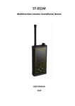
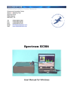
SIGNAL-T
160 Leninskiy av, ST . Petersburg, Russia, 196247
Phone: + 7(812) 677-10-75
е-mail: [email protected]
www.signal-t.ru
CATALOG 2015
Contact Details
SIGNAL-T
160 Leninskiy av
ST . Petersburg
Russia 196247
Phone: + 7(812) 677-10-75
E-mail: [email protected]
Internet: www.signal-t.ru
ST131 «PIRANHA II»,
ST 131N
Multifunctional detection
devices
ST 154
RF Monitoring System
ABOUT COMPANY
The team of company «SIGNAL-T» has been working on Information Security market since 1993.
The key directions of our activities are development and manufactures of equipment intended for detection of electronic
eavesdropping devices.
ST 110
RF detector
ST 167 “BETTA”
Search receiver
ST 167W
Search receiver
ST 169
Tester of cellular
and wireless data jammers
1
ST 131«PIRANHA II»,
ST 131N
Multifunctional
detection devices
PURPOSE
Multifunctional detection devices ST 131 PIRANHA-II and ST131N are intended for detecting and localization of eavesdropping devices as well as identification of natural and artificial sources of information leakage.
ST131N has additional option of NON LINEAR JUNCTION DETECTOR IN WIRE LINE.
The main types of the Bugging devices , for detection of which ST131 is designed are following:
The Bugging devices with transmission of information by radio channel:
RF microphones including devices with storage and subsequent transfer of information (burst transmitter)
and Frequency Hopping Spread Spectrum (FHSS);
RF stethoscopes.
Wireless cameras.
Mobile phones and modems of the CDMA, GSM, 3G, DECT standards used without authorization.
Devices using digital channels of data transmission of the 4G, WLAN and BLUETOOTH standards.
GPS tracker
The Hardware wiretap that use telephone, coaxial, security and fire alarm lines for information transfer in audio and
RF frequency range
Carrier Current Bug
The Bugs that are characterized by transmission of information in infrared, visible and ultrasonic frequency range
2
ST 131«PIRANHA II»,
ST 131N
Multifunctional
detection devices
DETECTION CHANNELS
ST 131 has four detection channel which cover frequency
range 10Hz -18GHz:
RADIO
0.01-18000 MHz
WIRE LINE
0.0003-3000 MHz
OPTICAL
770-1600/550-1100nm
ACOUSTOELECTRIC
0.01-125KHz
and option
NON LINEAR JUNCTION DETECTOR IN WIRE LINES for
ST 131 N.
The ST 131 is used in two basic use case:
“HANDHELD” This variant is intended for operational movement
on the survey area,
“STATIONARY” In this case the ST 131
is used with PC running special software
«ST 131 ANALYZER PRO».
3
ST 131«PIRANHA II»,
ST 131N
Multifunctional
detection devices
SPECIAL SOFTWARE «ST 131 ANALYSER PRO»
Detection of
pulse signals
Spectral, oscillographic and vector analysis
Using Templates
Data base of wireless standarts
Automatic analysis
and classification
of signals
“ST 131 ANALYZER
PRO” software expands capabilities of
ST 131 for analyzing
and processing of
signals.
24/7 Monitoring mode
4
Firmware
updates
via internet.
Waterfall mode
ST 131«PIRANHA II»,
ST 131N
Multifunctional
detection devices
SPECIFICATIONS
DIGITAL SIGNAL PROCESSING MODULE
Simultaneous processing frequency range, MHz
0.01-30
Resolution of ADC, bits
10, 14, and 16
Number of FFT points
32768 (with PC software)
512 (the ST131 main unit)
DDC filter bandwidth, MHz
0.0005-10 MHz
Demodulators
АМ, FM, SSB, TV (AM)
Detectors
RMS, average, peak-hold, quasi-peak
RADIO CHANNEL
Frequency range 1, MHz
0.01-30
Displayed noise level FULL RANGE, dBm
Minus 110 (minus 130 for PC software)
Input signal maximum level, dBm
5
Frequency range 2, MHz
30 - 4400
Displayed noise level
COMPLETE SET
Main unit
1
UHF converter ( ST 131.UHF)
1
Wire line adapter ST 131. AWL (ST 131. AWLN for ST 131 N)
1
• FULL RANGE, dBm
Minus 90 (minus 100 for PC software)
• 1 KHz bandwidth, dBm
Minus 110
Maximum input level, dBm
5
Analysis speed, not less, GHz/sec, at least
10
Input attenuation value, dB
0 - 30 with step 5
Identifiable standards of data communication
CDMA, GSM, 3G, 4G, WLAN, DECT
Frequency range 3, MHz
4000 - 18000
Threshold sensitivity, dBm
Minus 65
“WIRE” CHANNELS
Frequency range 1, KHz
0.3-15
Displayed noise range, not worse, dBm
Minus 115 (minus 140 for PC)
Common mode rejection ratio (CMRR), not less, dB
60
Wire line radio adapter ST 131. RAWL
1
Adapter «F- BNC-SMA»
1
Maximum allowed input voltage, V
250
Telescopic antenna
1
Frequency range 2, MHz
0.01-30
Broadband UHF antenna (ST 131.UHF.A)
1
Displayed noise level FULL RANGE, dBm
Minus 90 (minus 120 for PC)
Test Leads
1
Input signal maximum level, dBm
10
Maximum allowed input voltage, V
250
Frequency range 3, MHz
30-3000
Power supply unit
2
Main unit supporting block
1
Main unit shoulder holder
1
Tripod
1
USB cable
1
AA batteries
8
Headphones
1
USB flash drive
1
User manual
1
ADDITIONAL COMPLETE SET
1. SHF antenna-detector ST 131.SHF
2. Infrared probe ST 131.IR
3. Magnetic field probe ST 131.MAG
Displayed noise level FULL RANGE, dBm
Minus 90 (minus 100 for PC)
“OPTICAL” CHANNEL
Threshold sensitivity, dBm
Minus 70
Dynamic range, not worse, dB
75
Frequency range, MHz
0.01-10
“ACOUSTO-ELECTRIC” CHANNEL
Frequency range, KHz
0.01-125
Displayed noise level FULL RANGE, dBm
Minus 110 (minus 140 for PC software)
NON-LINEAR JUNCTION DETECTOR
Frequency of test signal, KHz
150-220
MAIN UNIT
Dimensions, mm
190 x 97 x 50
Weight (without batteries), kg
0.8
Indication
TFT, 3.5’’, 240x320, 262144 colors
Interface
USB 2.0, up to 224 Mbit/s
Supply current, A
0.4-0.6
Power supply
6 AA type batteries (or rechargeable
batteries)
4. Testing device ST 131.TEST
5
ST 131.TEST
Testing
device
PURPOSE
The «ST131.TEST» is intended to control operability of ST131.
The main unit has six control signal sourсes which provide a
check of all detection channels
SPETIFICATIONS
OUTPUT “UHF”:
Frequency, МHz Level of signal, dBm
Type of modulation Frequency of modulation, Hz
200, 600,1000, 1750,3500
-45+/-5
АМ, FМ, FHSS
300, 600, 1000, 1500
OUTPUT “СH2” AND SOURCE OF MAGNETIC FIELD ”MAG”:
Frequency, kHz
Level of signal, dBm
1, 5, 15, 60, 120
-35+/-5
OUTPUT “AWL”
Frequency, kHz
Level of signal, dBm
1, 3, 5, 10, 14, 500, 1000, 5000, 10000, 20000
-30+/-3
SOURCE OF SHF RADIO EMISSION “SHF”
Frequency, GHz
Type of modulation
8
PCM
SOURCE OF INFRARED EMISSION “IR”:
Spectral range, by level of 10%, nм
Type of modulation
750÷1100
PCM
POWER
Power
Maximal current consumption, mА
Dimensions of main unit, mm
COMPLETE SET
1. Main unit
2. Cable “RJ-45”
3. Cable “SMA-SMA”
4. Adapter “F-BNC”
5. Power supply
6
Li pol акк, 2.2А/h
<500
110X60X28
Additional probes
for ST 131 PIRANHA II and ST 131N
ST131.SHF SHF ANTENNA-DETECTOR
Frequency range, MHz
4000180000
Threshold sensitivity, W/cm2
2x10⁻¹⁰
Directional pattern width, degree
30-60
ST131.IR INFRARED PROBE
Frequency range, MHz
0.01-30
Dynamic range, dB, not worse
75
Spectral range, nm
770-1600
Angle of sight, degree
30
Total length of stand, м
0,9
Maximal angle of turn, degree
180
ST131.MF MAGNETIC FIELD PROBE
Frequency range, Hz
30 – 30000
Threshold sensitivity, A/m * Hz ,
less than
1/2
2x10⁻⁶
7
ST 154
RF Monitoring System
PURPOSE
The main purpose of the system is the detection of unauthorized transmission of data in the area of
surveillance.
These areas include::
Meeting rooms and offices
Exam rooms and testing facilities
Prisons and correctional facilities
Areas with limited use of cell phones, radios, etc.
KEY FEATURES
• Simultaneous monitoring from 1 to 128 local areas.
• No special training required.
• Many opportunities for selecting the configuration of the system.
• Data transmission over wired (ETHERNET) and wireless (WLAN) networks.
• 24/7 monitoring and the event log are provided
• The location finding mode for localization the source of transmission is available, when using multiple CMs or using special
SEARCH MODULE
ST154 DETECTS
RF Bugging devices
Сell phones and modems (CDMA450, GSM 900, GSM 1800, 3G)*, wireless data transmitters (4G, WLAN,
BLUETOOTH 2.4 and 5 GHz), cordless phone systems (DECT) as well as special technical devices using these data
transmission standards.
Analog radio listening devices
*the settings of cellular frequencies, depending on the country and mobile operator, are provided.
8
ST 154
RF Monitoring System
GENERAL DESCRIPTION
The main unit of the system is the control module (hereinafter CM) which
performs the reception and analysis of signals.
Detection area of the CM depends on many factors and the estimated
average value is 10 to 50 square meters.
In addition, there is the search module (SM) that ensures determination
the exact location of the radio transmission device.
SPECIFICATION
DESCRIPTION OF THE СM
THERE ARE FOUR TYPES OF MODULES:
ST154.A – Standalone CM Alarm indication carried out by sound and
light alarms which are located on the CM. Pre-installation parameters are
set via USB port.
This type of CM is intended primarily for the control within the one room.
ST154.W = ST154.A+ transmitting via WLAN to the PC
Technical specifications of the СM:
Frequency range
Threshold sensitivity, dBm
CDMA450, GSM900, SM1800, 4G,
3G
Maximum input level, dBm Interfaces USB, WLAN, ETHERNET
Supply voltage, V
Consumption current, mA, not more than
Dimensions without antenna mm
25-6000 MHz
-80
-100
-5
5
800
109x60x27
• ST154.E - ST154.A+ transmitting via ETHERNET to the PC
ST154.E+POE = ST154.A+ transmitting via ETHERNET with POE
to the PC
This variants of CM are intended for cover more than one room in a multistory building with alarm transmission on a computer.
9
ST 154
RF Monitoring System
Software
Configuration of the CM can be performed both individually and for
the whole system. Also there are many adjustable options.
Each CM is assigned its virtual image that allows to watch changes of
the radio emission in the real-time mode.
The logging mode is always enabled and there are a lot of options of
sorting events depending on criteria you need
Locating the source of the radio signal
For locating the source of the radio signal there are two ways:
• Processing data from three or more CM is available. Location of the RF
device will be immediately displayed on the floor plan.
• Use the SEARCH MODULE. Information
about the signal is transmitted to the SEARCH
MODULE via the USB port. The search is based
on the signal level indication on the screen of the
SEARCH MODULE.”
10
ST 167 “BETTA”
Search
receiver
PURPOSE
ST167 “BETTA” is intended for:
• detecting and locating of radio transmitting bugging devices in the
TSCM survey
• 24/7 monitoring
• Evaluation of employment of WLAN and DECT channels
• Measuring the level of the GSM, 3G, 4G base stations
KEY FEATURES
Detect of analog and digital signals in the 25 - 6000 MHz frequency
range
Special algorithms for identification of CDMA 450, GSM, 3G, 4G,
DECT, WLAN2.4, 5GHz and BLUETOOTH
Frequency measurement of analog signals
Sound control (AM and FM demodulation)
24 hour monitoring with the creation of a database of events. Work
on schedule.
Special mode Jammers detection, including GPS/GLONASS
SMS detection special mode
Separate indication of channels for 3G, 4G, DECT, WLAN 2.4 and
5GHz
Multiple range setting
Special software “ST167 ANALYZER”
Firmware update via internet
Extremely small dimensions for this type of device
11
ST 167
Search
receiver
SPECIAL SOFTWARE «ST 167 ANALYZER» allows:
SPECIFICATIONS
Create a database of logged events
Frequency range, MHz
25-6000
Threshold sensitivity, dBm
-80 (1000MHz)
Operate the device directly from a computer.
-55 (5000MHz)
Passband, MHz
2, 5, 10, 15,20
Average dynamic range, dB
70
Frequency measurements
10
accuracy, kHz
Power Supply
Li-Pol Battery 4.3V
(2.2A/h)
Average current consumption, mA
500
Interface
USB2.0
Overall dimensions main unit, mm
90X54X21
COMPLETE SET
Main unit
1
RF antenna
1
USB cable
1
Power supply
1
USB flash drive
1
USB flash drive witch software and «Technical
1
description and operating manual»
12
ST 167W
Search
receiver
PURPOSE
ST167W is a modification of ST167 “Betta”. The modification consists of adding WLAN module, which in combination
with the new firmware provides:
Displaying list of access points (WLAN), their names, MAC addresses, used channel and signal strength.
KEY FEATURES
Detect of analog and digital signals in the 25 - 6000 MHz frequency
range
Special algorithms for identification of CDMA 450, GSM, 3G, 4G,
DECT, WLAN2.4, 5GHz and BLUETOOTH
Frequency measurement of analog signals
Sound control (AM and FM demodulation)
24 hour monitoring with the creation of a database of events. Work
on schedule.
Special mode Jammers detection, including GPS/GLONASS
SMS detection special mode
Separate indication of channels for 3G, 4G, DECT, WLAN 2.4 and
5GHz
Multiple range setting
Special software “ST167 ANALYZER”
Firmware update via internet
Extremely small dimensions for this type of device
13
ST 110
Professional RF detector
PURPOSE
ST110 is designed for detecting and locating of radio
transmitting bugging devices, such as:
RF microphones, Including Burst transmitters and devices with
frequency hopping (Frequency Hopping Spread Spectrum - FHSS)
GPS TRACKER
GSM bugs
Wireless video cameras, stethoscopes
Unauthorized used WLAN and DECT devices
Principle of operation of ST110 is based on broad band
demodulation of electrical field.
KEY FEATURES
Separate indication of analog and pulse signals
Displaying of identified signals of GSM (2G), DECT, WLAN (2.4GHz)
Frequency meter
Oscilloscope
Timing diagram
Special software “ST110 ANALYZER”
Firmware update via internet
24/7 monitoring
Log of events
14
ST 110
Professional RF detector
SPECIAL «ST 110 ANALYZER» SOFTWARE is designed for:
SPECIFICATIONS
Main Unit
Frequency range, MHz
50-2500
Threshold sensitivity, dBm
minus 75 (50 МHz)
— view real time graphs of the operation on ST 110;
— the ST 110 remote full control using PC;
— extended settings assignment for MONITORING mode;
minus 70 (1500 МHz)
minus 50 (2500 МHz)
Dynamic Range of indication,
55 (50-2000 МHz)
dB
40 (2000-2500 МHz)
Sensitivity of frequency meter,
minus 35 (50 МHz)
dBm
minus 50 (500 МHz)
— load and display textual and graphical information of the operation
in MONITORING mode;
— firmware updating via internet.
minus 20 (2500 МHz)
Frequency measurement
accuracy, kHz
Cut-off frequency of LPF,
10
750
МHz
Built-in power supply battery
Li-pol 3.6V
Consumption current, mА
65
Dimension, mm
90x54x21
Weight, kg, not less
0.15
SHF antenna-detector ST 110.SHF
Frequency range, MHz
2000-7000
Threshold sensitivity, W/cm2
(2-9)*10-10
Dynamic Range, dB
45
Consumption current, мА
25
Dimension, mm
D=72, L=16
COMPLETE SET
Main block
1
HF antenna
1
USB cable
1
Power supply/Charger
1
USB flash drive
1
User’s Guide
1
ADDITIONAL COMPLETE SET
1. SHF antenna-detector «ST 110.SHF»
15
ST 169
Tester of cellular
and wireless data
jammers
PURPOSE
ST 169 is designed for estimating the emission level of jammers
that suppress signals of CDMA-450, GSM, 3G, 4G, Bluetooth,
DECT and WLAN data transmission standards.
Definition of the real area of suppression
A check of conformity the frequency range of the jammer to the
frequency range and channels of cellular and wireless data transmitters
Easy to use
Rapid results
OPERATION ALGORITHM
Measurement, processing and displaying the emission level of base
stations and jammers in numerical and graphical forms
Displaying the result of the check in the form of an information line.
KEY FEATURES
Selective reception of radio signals in the frequency ranges of selected
standards.
Comparison signals of the base stations and signal of jammer
Selection of suppression ratio
16
ST 169
Tester of cellular
and wireless data
jammers
SPECIFICATION
Frequency range, MHz
463-467.5
925-960
1800-1900,
2110 - 2170,
2400 – 2483.5
2600-2680
5150-5825
Threshold sensitivity, dB
925-960
1800 - 1900 2110- 2170
2400-2483.5 5150-5825
Average dynamic range, dB
65
Indication
OLED display 160x128
Power supply
Li-pol battery 2.2A/h
Interface
USB2.0
Overall dimensions of main unit, mm
90x54x21
-75
- 85
-77
-66
-50
COMPLETE SET
Main unit
1
HF antenna
1
USB cable
1
Charger/power supply
1
USB flash drive with the “Technical description and
operating manual”
1
17
ST121
Multifunctional
Advanced
Simulator
PURPOSE
ST121 is designed to simulate operation of almost all types of
bugging devices, such as:
RF microphone
Carrier current
Optical
Ultrasonic
It also imitates electromagnetic interference of electronic devices
(TEMPEST), such as solid state dictaphones and cell phones
PLACES OF ACTIVITY
Training of TSCM personnel
Testing functionality of the TSCM equipment
Laboratory measurement
KEY FEATURES
Complete signal generator in a wide frequency range: 0.01-20MHz and
100-6000MHz
Self-powered
Small dimensions
Robust design
18
ST121
Multifunctional
Advanced
Simulator
TECHNICAL SPECIFICATIONS
“RF/UHF” socket
Frequency range, MHz
100-6000
Frequency-tuning step, kHz
10, 100, 1000, 10000, 100000
Signal level, dBm
-42 – +14
Signal
Sinusoidal, DSSS ,FHSS, PULSE
Modulation
AM, FM
Data transmission standards for imitation
GSM, 3G, DECT, WLAN,
BLUETOOTH
Bandwidth of Hopping, MHz
1, 6, 10, 20, 50, 100
Number of Hopping Channels
25, 50, 125, 250
FHSS frequency of hopping, Hz
1, 2, 4, 8
DSSS bandwidth, MHz
0.3, 0,5, 1, 2, 4
PULSE Signal transmission time, sec
0.0001- 99
PULSE Signal accumulation time, sec
0.01-5999
“RJ-45” socket
COMPLETE SET
Main module
HF antenna
«RJ-45» cable
«220V» cable
1
1
1
1
Frequency range, kHz
0.01-20000
Maximum signal amplitude, V
3.5
Modulation
AM, FM, PWM
“220V” socket
Frequency range, kHz
30-20000
Maximum signal amplitude, V
3.5
Maximum input voltage, V
380
Modulation
FM, DSSS, PWM
“IR” emitter
Wave length, nm
940
Subcarrier frequency range, kHz
0.01- 5000
Modulation
AM, FM, DSSS
“LF” socket
Frequency range, kHz
0.01-120
Maximum output power, W
0.7 (power supply),
Impedance, Ω
8
Modulation
AM, FM, DSSS
Magnetic field emitter
Equivalent magnetic moment of magnetic field source
with frequency 1kHz, A*m2
“3/RJ-45” cable
1
2*10-4
Power
Power supply
Li-Polymer battery, 2.2A/h or 220V
Main module dimensions, mm
110X60X28
Power supply/charger 5V/1A
Technical description and operating manual
1
19
Contact Details
SIGNAL-T
160 Leninskiy av
ST . Petersburg
Russia 196247
Phone: + 7(812) 677-10-75
E-mail: [email protected]
Internet: www.signal-t.ru
ST131 «PIRANHA II»,
ST 131N
Multifunctional detection
devices
ST 154
RF Monitoring System
SIGNAL-T
160 Leninskiy av, ST . Petersburg, Russia, 196247
Phone: + 7(812) 677-10-75
е-mail: [email protected]
www.signal-t.ru
CATALOG 2015