1
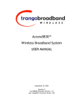
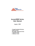
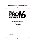
A
Access5800 Series
User Manual
Febuary 26, 2003
•Trango Broadband Wireless
•15070 Ave. of Science, Ste. 200
•San Diego, California 92128
•T 858-653-3900
•F 858-621-2725
Trango Broadband Wireless Access5800™ User Manual
Copyright 2001 Trango Broadband Wireless, A division of Trango Systems, Inc.
No part of this publication may be reproduced in any form without the written
permission of the copyright owner.
The information in this publication is subject to change without notice. Trango
Broadband Wireless shall not be liable for errors contained herein or for
incidental or consequential damages in connection with the furnishing,
performance, or use of this manual or the equipment it refers to.
FCC Information:
This device complies with Part 15 of the FCC Rules. Operation is subject to the
following two conditions: (1) This device may not cause harmful interference, and
(2) this device must accept any interference received, including interference that
may cause undesired operation.
This equipment has been tested and found to comply with the limits for a Class B
digital device, pursuant to Part 15 of the FCC Rules. These limits are designed to
provide reasonable protection against harmful interference in a residential
installation. This equipment generates, uses, and can radiate radio frequency
energy, and if not installed and used in accordance with these instructions, may
cause harmful interference to radio communications. However, there is no
guarantee that interference will not occur in a particular installation. If this
equipment does cause harmful interference to radio or television reception, which
can be determined by turning the equipment off and on, the user is encouraged to
correct the interference by one of more of the following measures:
1) Reorient the antenna;
2) Increase the separation between the affected equipment and
the unit;
3) Connect the affected equipment to an outlet on a different
circuit from that whic h the receiver is connected to;
4) Consult the dealer and/or experienced radio/TV technician for
help.
FCC ID: NCYM5800SBAP60
FCC ID: NCYM5800SBSUEXT
CANADA: 2945A12100
IMPORTANT NOTE:
Intentional or unintentional changes or modifications not expressly approved by the party
responsible for compliance must not be made. Any such modifications could void the user’s
authority to operate the equipment and will void the manufacturer’s warranty.
2
User Manual Rev F
Trango Broadband Wireless Access5800™ User Manual
CONTENTS
1.
For your safety.................................................................. 4
2.
Welcome......................................................................... 4
2.1.
Documentation conventions .................................................. 4
2.2.
Check List....................................................................... 5
2.3.
Service .......................................................................... 5
3.
Components and Features..................................................... 6
3.1.
System Overview............................................................... 6
3.2.
Access Point Unit .............................................................. 6
3.3.
Junction Box.................................................................... 7
3.4.
Subscriber Unit................................................................. 7
4.
Installation ...................................................................... 8
4.1.
Access Point Mechanical Installation........................................ 8
4.2.
Subscriber Unit Mechanical Installation .................................... 8
4.3.
Wiring ..........................................................................10
4.4.
Antenna Alignment ...........................................................10
4.5.
Grounding ......................................................................11
5.
Setup ............................................................................12
5.1.
Step by Step Configuration of The AP ...................................12
5.2.
Step by Step Configuration of The SU...................................23
6.
Site Planning ...................................................................28
7.
Administration Tools ..........................................................37
7.1.
Network Security .............................................................37
7.2.
Subscriber Database Management ..........................................37
8.
SNMP ............................................................................38
8.1.
Overview .......................................................................38
8.2.
Setup ...........................................................................40
9.
Troubleshooting ...............................................................41
10.
Theory of Operation .......................................................45
10.1.
Hardware ....................................................................45
10.1.1.
5.8 GHz Direct Sequence Spread Spectrum ..........................45
10.1.2.
Antenna Technology ....................................................45
10.2.
Software.....................................................................45
11.
Specifications...............................................................47
11.1.
M5800S-AP-60 Specifications .............................................47
11.2.
M5800S-SU Series Specifications .........................................50
APPENDIX: FIRMWARE – HARDWARE CROSS REFERENCE ............................54
3
User Manual Rev F
Trango Broadband Wireless Access5800™ User Manual
1. For your safety
WARNING
Use extreme care when installing antennas near power lines.
CAUTION
Do not apply power to the transmitter until the antenna is
connected. Permanent damage may result.
CAUTION
When the unit is in operation, avoid standing directly in
front of the antenna. Strong RF fields are present when
the transmitter is on.
2. Welcome
Thank you for choosing Trango Broadband Wireless to fulfill your wireless Internet
access needs. You are now on your way to using a high-speed wireless link, which can
serve as an alternative to conventional wiring where such wiring is impractical, too
slow or too expensive.
2.1. Documentation conventions
Convention
Description
Bold
Indicates emphasized
text
Example: Note
Italic
Indicates a file name
Example:
ap_default.cfg
Bold & italic
Indicates a user command
or GUI screen
Example: tftp
Indicates contents in a file
Courier New
Courier New
Indicates descriptions of
file contents
4
User Manual Rev F
Trango Broadband Wireless Access5800™ User Manual
2.2. Check List
For each package you receive, you should have the following items:
AP Package
Quantity
Access5800 TM Access Point Radio
Access5800 TM Quick Setup Check List
V-shaped Mounting Brackets
Bolts (for Mounting Brackets)
Lockwashers (for Mounting Brackets)
Junction Box
Power Adapter
Programming Cable
Mounting Arm with U-bolts
1
1
2
4
4
1
1
1
1
SU Package, with external antenna
Quantity
TM
Access5800 Subscriber Unit Radio
Access5800 TM Quick Setup Check List
V-shaped Mounting Brackets
Bolts (for Mounting Brackets)
Lockwashers (for Mounting Brackets)
Junction Box
Power Adapter
Coaxial Cables
Dish Antenna Kit with Feed Element
1
1
2
4
4
1
1
2
1
SU Package, with internal antenna
Quantity
TM
Access5800 Subscriber Unit Radio
Access5800 TM Quick Setup Check List
V-shaped Mounting Brackets
Bolts (for Mounting Brackets)
Lockwashers (for Mounting Brackets)
Junction Box
Power Adapter
Mounting Arm
1
1
2
4
4
1
1
1
Part Number
M5800S-AP-60
LT-9005
ES-9181
H-9138
H-9137
320-9014
PT-9005
CA-9013
H-9125
Part Number
M5800S-SU-EXT
LT-9005
ES-9181
H-9138
H-9137
320-9014
PT-9005
CA-9018
AD5800-27-D
Part Number
M5800S-SU
LT-9005
ES-9181
H-9138
H-9137
320-9014
PT-9005
H-9125
If any items are missing, notify your sales representative. If an item appears to be
damaged from shipment, replace it in its packing material and notify the shipper.
2.3. Service
5
User Manual Rev F
Trango Broadband Wireless Access5800™ User Manual
If the unit ever needs repair service, contact your service provider or Trango
Broadband Wireless for return authorization and shipping instructions.
3. Components and Features
3.1. System Overview
The Access5800 wireless Internet access system is designed for sending and
receiving Ethernet based data traffic where conventional wiring is impractical
or when higher connection speeds are required. The system utilizes robust 5.8
GHz spread spectrum technology to reduce susceptibility to interference. The
basic system consists of one M5800S-AP-60 access point (AP) and up to 512
M5800S-SU series subscriber units (SUs). The AP uses a proprietary polling
mechanism to dynamically allocate bandwidth to the SUs on an as-needed basis
based upon service level agreement (SLA) rules (CIR and MIR). The system has
a maximum service radius of 10 miles line of sight (LOS) and a burst rate of 10
Mbits/second either upstream or downstream.
3.2. Access Point Unit
The Access Point Unit coordinates and manages Ethernet packet flow based on
a point-to-multipoint Broadband Wireless Access architecture.
Back
Front
3
1
4
2
12345678-
5
Access Point Unit
Radome
Mounting bolt with
Nuts (4) (built-in)
Mounting arm (incl.)
"V" brackets (incl.)
Ethernet connection
and power
Serial connection
(inside access door)
LED's display
TX: red
RX: green
RSSI: yellow
Bottom
6
6
7 8
User Manual Rev F
Trango Broadband Wireless Access5800™ User Manual
3.3. Junction Box
The Junction Box provides power to AP or SU via unused leads in a Shielded
Twisted-pair (STP) Ethernet cable. The ODU port in the diagram below
connects to AP or SU using 8-conductor STP.
1
1-
Indicates voltage to
J-Box OK
2-
NET port (RJ45)
3-
Indicates AP or SU
drawing current
4-
ODU port (RJ-45)
5-
Power port (20 Vdc)
3
2
4
5
3.4. Subscriber Unit
The Subscriber Unit interfaces with end users via Ethernet devices such as
network switch, hub or a PC network interface card (NIC).
Back
Front
1
2
12345678910-
Installed on dish
antenna mount
arm
Subscriber Unit
Antenna ports (H & V)
Mounting bolt and nuts
(4)(built-in)
"V" brackets (incl.)
Dish antenna
Feed arm
Feed
Flange Ethernet
connection and power
Serial connection
3
4
(inside access door)
LED display
TX: red
RX: green
RSSI: yellow
Bottom
5
6
1
7
10
8
7
9
User Manual Rev F
Trango Broadband Wireless Access5800™ User Manual
4. Installation
Installation of antennas and radio equipment can be very dangerous. Use
extreme caution when installing equipment near power lines. Electrostatic
Discharge (ESD) protection should be used on any Ethernet cable entry into a
building. APC provides equipment to accomplish this.
4.1. Access Point Mechanical Installation
(1) Mount the arm to
an earth-grounded
mast or secured wall.
U-bolts required for
mast mount
(2) Mount the AP to
the mounting arm
(3) Align antenna
4.2. Subscriber Unit Mechanical Installation
(1) Mount the arm to
an earth-grounded
mast or a secured
wall (U-bolts
required for mast
mount).
(2) Assemble the
antenna dish and
feed arm (upper left
picture). The lower
right picture shows
the dish with feed
arm.
8
(3) Mount the dish
to the mounting
arm.
User Manual Rev F
Trango Broadband Wireless Access5800™ User Manual
(4 Mount the feed
) the feed arm.
to
(7) Connect one end
of two RF cables to
the feed and run
other end through
feed arm to the SU.
(5) Adjust the
mounting arm to
horizontal level.
(8) If the AP is at the
horizon, rotate the dish
to the 50 mark.
(6) Mount SU on the
mounting arm.
(9) If the AP is not at the
horizon, use the 50 mark
as the offset point and
direct the SU antenna up
or down until the RSSI is
acceptable.
(10) Slightly adjust the
dish antenna up and
down, left and right
until the strongest RSSI
is reached. Then
tighten down the bolts.
9
User Manual Rev F
Trango Broadband Wireless Access5800™ User Manual
4.3. Wiring
Wiring diagram is shown as below: (please note that the Junction Box is an
indoor device that requires a dry environment. STP stands for shielded
twisted-pair, and UTP for unshielded twisted-pair.)
AP Wiring
UTP or STP
STP
ATM/IP
20 Vdc
WAN
110V 50~60 Hz
SU Wiring
H
V
UTP or STP
STP
ATM/IP
20Vdc
WAN
110V 50~60 Hz
UTP or STP
(crossover)
STP
Wiring when only
connected to 1 PC
20Vdc
110V 50~60 Hz
It is recommended that only 24 AWG shielded twisted pair (STP) be used for the
connection between the junction box and AP or SU. Using the 20 volt power
adapter supplied with the unit, the max Ethernet cable length from the radio
to PC/hub/switch is 100 meters (328 feet). Since power is sent over four of
the unused conductors in the 8 conductor STP, the resistance is reduced
significantly, reducing the voltage drop along the cable.
4.4. Antenna Alignment
The target RSSI for SU with different antenna is shown as follows:
SU with panel antenna: -70dBm for 3 miles radius with 12dB fade margin
10
User Manual Rev F
Trango Broadband Wireless Access5800™ User Manual
SU with dish antenna: -70dBm for 10 miles radius with 12dB fade margin
The RSSI reading can be obtained by following two methods:
i.
View the RSSI reading from a laptop computer (This is a more
accurate reading and the radio has to be in “Off” mode to use the
command below. This is the preferred way to align the antenna.)
1.
2.
ii.
Telnet into the SU using the new IP address or use a Hyperterminal
session.
Read the RSSI level continuously. (ssrssi <channel #>
<polarization>) Hit space bar and enter to escape.
View the yellow LED indicator in the box (This is an approximate reading
and the radio has to be in SU mode for the LED to function). Activate SU
mode with the command, opmode su y.
1.
2.
RSSI > -80dBm - blinking. (lowest strength displayed to LED)
RSSI ? -65dBm - solid. (duty cycle increases with signal strength)
An example of antenna alignment with the 27dBi parabolic antenna is shown
below.
The picture above illustrates that you shall down tilt the antenna 22.5° to
point to the horizon.
4.5. Grounding
Attach a ground strap of 12 AWG stranded copper from the mounting bracket to
the earth grounded mast.
It is important to note that the shielded connectors at the junction box are not
connected to the ground on the power adapter to avoid a ground loop. By
11
User Manual Rev F
Trango Broadband Wireless Access5800™ User Manual
using a static protection device on the Ethernet cable at the building entry any
currents induced by lightning or static will be kept outside and routed to earth
ground.
It is recommended that metal conduit be used over the STP if possible to
prevent damage to the STP and add a measure of shielding.
5. Setup
Configuration of the AP and SU units must be done prior to deployment.
The default IP address for the radio is 192.168.100.100. Please set up your
computer to the same subnet as the radio (i.e. IP address 192.168.100.110
and subnet mask of 255.255.255.0). Type http://192.168.100.100 on the
address bar of the WEB browser to get into the radio. The default logon
password is: trango.
5.1. Step by Step Configuration of The AP
The above diagram is the information page that you will see once you get in.
In general, the HTTP interface consists of three sections: navigation (upper
left, circled in dash), status (lower left, circled), and content (rest of the
page).
?? Navigation: Provide browsing capability to different pages.
12
User Manual Rev F
Trango Broadband Wireless Access5800™ User Manual
?? Status: Provide status (on/off) of the radio
?? Content: Provide contents of a specific page
Configuration Page:
This HTML page is used to set up basic configuration of the AP.
13
User Manual Rev F
Trango Broadband Wireless Access5800™ User Manual
Base ID: This parameter specifies the cluster that the AP belongs to. It is one
of the three key pieces of information, along with active channel, and
subscriber database information for the link establishment between the AP
and other SU’s. All AP’s and SU’s in the same cluster (hexagon) shall have the
same Base ID. The planning of Base ID is illustrated in the diagram below. The
same Base ID can be re-used every seven clusters.
Baseid = 2
Baseid = 7
Baseid = 3
Baseid = 1
Baseid = 6
Baseid = 4
Baseid = 5
AP ID: This parameter is currently NOT used. The planning of AP ID can be
found in the diagram below.
6
1
4
3
5
6
2
1
5
2
4
3
6
1
4
3
5
6
2
4
1
4
3
6
1
4
3
2
2
1
5
6
5
5
3
6
1
4
3
5
2
2
IP Address: The parameter specifies IP address of the AP. Subnet mask for the
radio is 0.0.0.0, with NO default gateway. Please note that this radio is layer-II
device—MAC device. The IP address here is for provisioning or network
management via TCP/IP. The radio still passes traffic in spite of the different
settings of IP address.
14
User Manual Rev F
Trango Broadband Wireless Access5800™ User Manual
Default Opmode: This parameter controls the state (ap or off) of the radio
after reboot/power cycle. When the parameter is set to ap, the radio will get
into ap mode automatically after reboot/power cycle.
In case you want to interrupt the boot up routine, you can telnet/HTTP into
the radio within 30 seconds time window. As the result, the radio will stay in
off mode.
Switch (Block Broadcast and Multicast Packets): This switch enables/disables
the blocking of Ethernet control packet except ICMP and ARP to reduce the
amount of unnecessary overhead introduced to the wireless link.
Switch (Activate SU to SU Communication): This switch enables/disables the
peer-to-peer feature among SU’s through the AP. Before the switch is turned
on, all SU’s that want to communicate with each other have to be assigned to
the same group. (See SU to SU Group)
Switch (Broadcast Time Stamp to SU): This parameter is NOT used at this
time. Please leave the default unchaged.
Active Channel: This parameter specifies the channel number and polarization
the radio operates on.
Remarks: This parameter documents radio information (i.e. customer name,
address of installation, and so on). Maximum 28 characters can be stored.
Button (Save and Activate Settings): This button will save settings mentioned
above to persistent storage, then active them.
Hyperlink (Add Subscriber): This hyperlink will take you to Subscriber
Database page.
Hyperlink (Activate Opmode): This hyperlink will activate the radio from off
mode to ap mode.
Hyperlink (Reboot System): This hyperlink will reboot the system. The radio
will go into the ap/off state based on the setting of Default Opmode. The
whole process will take 60 seconds.
Advanced Setup Page:
15
User Manual Rev F
Trango Broadband Wireless Access5800™ User Manual
RF Tx Power: This parameter specifies the power output of the radio,
excluding the antenna gain.
Service Radius: This parameter specifies the distance of the furthest SU this
AP will serve. Based on this information, the AP will determine the maximum
wait time for an SU to response to a poll before it starts to poll the next one.
Note: This parameter has NO effect on the actual coverage radius of the radio.
Channel Table: This table allows you to create your own channel instead of the
manufacturing defaults in the AP. Keep in mind that channel width is 20MHz,
and the frequency specified here is the center frequency. For example,
channel#1 (5736MHz) means that channel 1 starts at 5726MHz and ends at
5746MHz. Please remember that the settable frequency range is (5736MHz,
5836MHz).
RF Rx Threshold: This parameter specifies the receiver sensitivity of the AP.
It is a powerful tool when the radio is in a noisy environment. By default, the
radio’s sensitivity is –82dBm for a 1 x 10 E-6 BER. The higher the threshold
(less negative) is, the less sensitive the radio will be. For example, the radio is
less sensitive with RF Rx Threshold set to –60 than –80.
The setting of this shall be hand-in-hand with the setting of Target RSSI from
SU below.
Incremental Sensitivity
of the Radio
-60
-65
-70
-75
-80
16
User Manual Rev F
Trango Broadband Wireless Access5800™ User Manual
Target RSSI From SU: This parameter specifies the target RSSI from all SU’s to
the AP. Based on this parameter, the AP can power level each SU so that it
receives same level of signal strength from all SU’s, regardless far or near.
Please note that when you set the Target RSSI from SU, you need to consider
AP’s rfrxthreshold. If the rfrxthreshold were higher than the Target RSSI From
SU (says –70dBm for rfrxthreshold and –75dBm for Target RSSI From SU), the AP
would never be able to hear from these SU’s.
We must set the Target RSSI From SU 5dB higher than the rfrxthreshold. When
the rfrxthreshold is disabled, the setting of Target RSSI from SU shall be no less
than –75dBm.
MIR Threshold: This parameter serves 2 purposes. 1) Enable/Disable the MIR
Threshold; 2) Specify the MIR threshold.
?? When MIR Threshold is disabled, the AP will serve MIR for all its SU’s.
?? When MIR Threshold is activated, and the network traffic exceeds the
MIR threshold, the AP will only serve CIR for all its SU’s.
?? When MIR Threshold is activated, and the network traffic does NOT
exceed the MIR threshold, the AP will still serve MIR for all its SU’s.
Site Survey Page:
This HTML page is used to verify the RF environment the AP is operated in. To
start the survey, please specify the duration of the test (in minutes), and the
channel polarization, then click the Start Survey Button.
Please note that the radio must be on off mode to do site survey.
17
User Manual Rev F
Trango Broadband Wireless Access5800™ User Manual
The result of the survey will look something like below, “yes” indicates clean
channel while “no” indicates noisy channel. A channel is clean when the Avg
dBm and Peak dBm of a signal is 8dB weaker than the radio’s sensitivity
(rfrxthreshold).
Subscriber Database Page:
18
User Manual Rev F
Trango Broadband Wireless Access5800™ User Manual
Current Subscriber(s) Table: This table (circled in dash) contains database for
all subscribers this AP serves, one row per SU. This table is empty by default.
Entries for each SU are described below:
SU ID: This parameter is Subscriber ID (1~8190) of an SU. Each
subscriber in a sector shall have a unique ID.
Type: This parameter is service level, regular or priority, of an SU. The
AP will poll priority user more often, thus better network latency as the
result. As the network latency varies based on the number of subscriber
units the AP serves, priority user is guaranteed that the latency is NOT
greater than 100ms regardless of the size of the network.
SU to SU Group: This parameter is peer-to-peer group this SU belongs
to. With the SU to SU switch turned on, SU’s in the same peer-to-peer
group can communicate to each other via the AP. There are totally 15
groups (1~F hexadecimal number) available. Please note that the SU
shall be set to priority user for this feature to improve latency.
CIR: This parameter is the Committed Information Rate (in Kbps) the AP
allocates the SU.
MIR: This parameter is the Maximum Information Rate (in Kbps) the AP
allocates the SU.
19
User Manual Rev F
Trango Broadband Wireless Access5800™ User Manual
Device ID: This parameter is the MAC address of the subscriber unit,
which can be found on the back of the SU.
Modify and Save Button: This button allows you to save the changes on SU ID,
Type, SU to SU Group, CIR, and MIR field to the subscriber database.
Add and Save Button: This button allows you to save the addition of subscriber
to the subscriber database, one at a time.
Delete and Save Button: This button allows you to save the deletion of
subscriber from the subscriber database, one at a time.
Link Control Page:
This HTML page is used to verify the link between an AP and SU after the
minimum setup is done, which includes the Configuration page and the
Subscriber Database page.
Please note that both AP and SU shall be in opmode (ap or su) before getting
into this page. Otherwise, you will receive an error message of “This function
is disabled when opmode is OFF”. To activate the radio, please refer to above
Active Opmode hyperlink under the Configuration Page.
SU Association Status Table: This table shows association status for all SU’s in
the sector that is served by this AP. There are three states in this table that
will be described in details as follows:
20
User Manual Rev F
Trango Broadband Wireless Access5800™ User Manual
Associated: Indicate those SU’s are currently associated with the AP.
Associating: Indicate those SU’s are associating with the AP.
Power Off: Indicate those SU’s are neither associated nor associating
with the AP.
RF Link Loopback Test: In this test, the AP sends packets to a specified SU,
the SU then echoes those packets back to the AP, and the successful packets on
both directions are calculated. Packet size of 1512 Bytes is used in the test.
To start the test, please specify the SU ID and run time (in minutes), then click
the Loopback Test button. Once the test is completed, the test result is
shown as follows:
SU Ranging/RSSI Test: In this test, as shown in the figure below, following data
will be reported in order. 1) Distance (AP to the specified SU); 2) RSSI (SU>AP); 3) RSSI (AP->SU); 4) SU Transmit power; 5) SU temperature. The test will
take 10 seconds. To start the test, please specify the SU ID, then click the
Ranging Test button.
Power Level All Associated SUs: The Powerleveling button underneath this
field is for the AP to start the power leveling process that controls the power
output of all SU’s it serves. The power output of these SU’s depends on the
Target RSSI From SU mentioned on the Advanced Setup Page. This process will
take 10 seconds for each SU.
21
User Manual Rev F
Trango Broadband Wireless Access5800™ User Manual
Command Console Page:
The Command Line Interface can be used here. Type “?” to show all available
commands.
In addition to the Command Console, you can also run these commands via
TELNET or hyper terminal. The setting for hyper terminal is: 9600, 8-N-1, no
flow control. To telnet or hyper terminal into the radio, a password is
required. The defaulted password is “trango”.
Detailed syntax and usage description of these commands can be found in
“User Command Set Reference Manual”.
22
User Manual Rev F
Trango Broadband Wireless Access5800™ User Manual
5.2. Step by Step Configuration of The SU
System Information Page:
Configuration Page:
SU ID: This parameter is Subscriber ID (1~8190) of an SU. Each subscriber in a
sector shall have a unique ID.
Switch (Block Broadcast and Multicast Packets): This switch enables/disables
the blocking of Ethernet control packet except ICMP and ARP to reduce the
amount of unnecessary overhead introduced to the wireless link.
Switch (Auto Scan AP): This switch enables/disables the SU to look for another
AP on a different channel when the previous link with an AP is down.
This redundancy feature is only available when you have 2 AP’s serving the
same sector. See Scan AP Sequence below for channel setting.
Switch (TCP/IP Service for AP): This switch enables/disables the SU to accept
TCP/IP request from the AP side. When the switch is turned on, you can
ping/HTTP/telnet into the SU from the AP side. Please note that this switch
has no effect on the SU accepting TCP/IP request from the SU side when the SU
is in su mode.
23
User Manual Rev F
Trango Broadband Wireless Access5800™ User Manual
Scan AP Sequence: This field specifies the primary channel and secondary
channel the SU uses. The first entry in the sequence is primary, and the next
one is secondary. It works hand in hand with Switch (Auto Scan AP).
Advanced Setup Page:
Channel Table: This table allows you to create your own channel instead of the
manufacturing defaults in the SU. Keep in mind that channel width is 20MHz,
and the frequency specified here is the center frequency. For example,
channel#1 (5736MHz) means that channel 1 starts at 5726MHz and ends at
5746MHz. Please remember that the settable frequency range is (5736MHz,
5836MHz). The channel table must be matched with the one in the AP.
RF Rx Threshold: This parameter specifies the receiver sensitivity of the SU.
It is a powerful tool when the radio is in a noisy environment. By default, the
radio’s sensitivity is –82dBm for a 1 x 10 E-6 BER. The higher the threshold
(less negative) is, the less sensitive the radio will be. For example, the radio is
less sensitive with RF Rx Threshold set to –60 than –80.
Incremental Sensitivity
of the Radio
-60
-65
-70
-75
-80
24
User Manual Rev F
Trango Broadband Wireless Access5800™ User Manual
Site Survey Page:
This HTML page is used to verify the RF environment the SU is operated in. To
start the survey, please specify the duration of the test (in minutes), and the
channel polarization, then click the Start Survey Button.
Please note that the radio must be on off mode to do site survey.
25
User Manual Rev F
Trango Broadband Wireless Access5800™ User Manual
The result of the survey will look something like below, “yes” indicates a clean
channel while “no” indicates a noisy channel. A channel is clean when the Avg
dBm and Peak dBm of a signal is 8dB weaker than the radio’s sensitivity
(rfrxthreshold).
Command Console Page:
26
User Manual Rev F
Trango Broadband Wireless Access5800™ User Manual
The Command Line Interface can be used here. Type “?” to show all available
commands.
In addition to the Command Console, you can also run these commands via
TELNET or hyper terminal. The setting for hyper terminal is: 9600, 8-N-1, no
flow control. To telnet or hyper terminal into the radio, a password is
required. The defaulted password is “trango”.
Important Note: While the SU is in su mode, it does NOT accept any ping or
TELNET from the SU side. In order to do that, you need to power cycle the SU,
and telnet into the SU within the 30 seconds window.
Detailed syntax and usage description of these commands can be found in
“User Command Set Reference Manual”.
27
User Manual Rev F
Trango Broadband Wireless Access5800™ User Manual
6. Site Planning
6.1. Cell Configuration
The system is designed to support a hexagonal six sector cell design, with each
sector containing 1 or 2 AP units. This cell design has a 360 degree coverage
area and can support up to 6000 concurrent subscriber connections. Each
sector uses a single antenna polarization which does not change and is opposite
of the adjacent sectors. Section 3.3 below has more detail on assigning
channels and polarizations to the sectors.
Other cell architectures are available, but should only be used after careful
planning.
6.2. Service Range Control
Several features allow the control of the service range to prevent interference
from distant cells or other sources, and to allow smaller cells in densely
populated areas. Each is discussed below.
6.2.1.
Threshold Control
This feature limits the sensitivity of the receiver section of the radio,
preventing the radio from “hearing” distant transmitters and attempting to
lock to them. This is one of the most powerful ways to avoid interference
from other equipment operating in the same frequency band.
6.2.2.
Service Range Control
This feature reduces the time an AP will wait for a response from an SU, which
makes it impossible for SUs located outside the range to establish
communication with the AP. Also, the data throughput will increase slightly as
the service range is reduced. Shorter range has a smaller receive window,
improving resistance to interference. The target RSSI should be adjusted if this
parameter is changed from the default. Also special attention must be paid to
the antenna height used versus the service range.
6.2.3.
Power Leveling
RF power leveling is a feature that is typically found in more elaborate mobile
systems such as cellular CDMA networks. It does have great benefits for
wireless broadband access systems and therefore is included in the Access5800
28
User Manual Rev F
Trango Broadband Wireless Access5800™ User Manual
design. Using this feature, all SUs have their RF power output adjusted until
the signal strength for each SU as received in the AP is roughly the same.
The key advantage is that the SUs close to a basestation AP on channel #1 that
have their power turned down will not cause interference to an AP on channel
#2 at the same basestation and vise-versa. Cell planning is made much easier
since the adjacent channel interference is reduced significantly.
When the SU is powered on and begins to associate with an AP, the AP will run
the unit through a routine in which it increases or decreases the SU RF power
until the received power at the AP is as close to the target RSSI as possible.
6.3. Channel Flexibility
Since the AP channels may be changed remotely and the SU may be set up to
automatically scan a programmable set of channels and polarizations, changing
the channel and polarization of a given sector is very simple and may be done
at any time with a minimum of down time.
There are several rules that should be observed regarding channel planning.
A minimum of 20 MHz should be used for channel spacing on the same
polarization.
In the same sector always use a spacing of at least 26 MHz between channels
for each AP if two or more APs are covering the same area.
Only reuse frequencies for APs on opposite polarizations that are mounted 180o
relative to each other in the cell and well isolated. Verify that the APs do not
interfere with each other by running “cf2cf” on one AP while running site
survey on the other. Increase separation distance if necessary, add physical
shielding, or reduce each AP’s RF power output.
Always align APs in adjacent cells so that they do not face each other directly.
6.4. Channel Planning
1, 3, 5 V
1, 3, 5 H
or
and
and
2, 4,6 H
2, 4,6 V
Single Sector
29
User Manual Rev F
Trango Broadband Wireless Access5800™ User Manual
6H 1V
4V
3H
2H 5V
6H 1V
4V
6H 1V
3H
4V
2H 5V
3H
2H 5V
6H 1V
4V
3H
2H 5V
6H 1V
4V
6H 1V
3H
4V
2H 5V
3H
2H 5V
6H 1V
4V
3H
2H 5V
Six Sector (6 AP’s)
3, 6 H
2, 5 V
3, 6 H 1, 4 V
2, 5 V
1, 4 H
2, 5 H
3, 6 V
2, 5 H
1, 4 H 3, 6 V
3, 6 H 1, 4 V
3, 6 H
1, 4 H
1, 4 V
1, 4 V
2, 5 H
1, 4 H
3, 6 V
3, 6 H
1, 4 V
2, 5 H
3, 6 V
2, 5 H
1, 4 H 3, 6 V
3, 6 H
2, 5 V
2, 5 V
2, 5 V
1, 4 V
2, 5 V
3, 6 H
2, 5 V
1, 4 H
1, 4 V
1, 4 H
2, 5 H
3, 6 V
2, 5 H
3, 6 V
Six Sector with (12 AP’s)
30
User Manual Rev F
Trango Broadband Wireless Access5800™ User Manual
6.5. Path Loss Planning
This section addresses the planning of the radio link parameters between the
AP and SU. The Access5800 system is designed for line-of-sight (LOS) AP to SU
links up to 10 miles using the M5800S-SU-EXT with 27 dBi dish antenna with a
fade margin allowance of 12 dB. Using the M5800S-SU ( with internal antenna),
the LOS range is 3.2 miles for a 12 dB fade margin.
The link budget is a summation of all system component gains and losses to
determine if sufficient signal is prese nt at the radio antenna for the link to
perform properly. The link budget is calculated for each direction of the link.
The general equations are as follow:
Required system gain = Free space loss (FSL) + fading margin allowance(FM)
Calculated system gain = Transmit antenna gain (dB) + transmit power (dBm)
+ receive antenna gain – receiver sensitivity (dBm).
For the link to work properly Calculated system gain must be greater than or
equal to the Required system gain.
Example:
For the M5800S AP to SU (with dish) 10 mile LOS link, the FSL is 132.11 dB
from 6.5.1 below. We set the fade margin in this case at 12 dB to allow for
rain only per Section 6.5.2 below.
The total required system gain is then 132.11 + 12 = 144.11 dB
AP to SU:
Transmit Antenna:
17 dB
Transmit Power:
+18 dBm
Receive Antenna Gain:
27 dB
Receiver sensitivity:
-82 dBm
Calculated System Gain = 145 dB
SU to AP
Transmit Antenna:
27 dB
Transmit Power:
+18 dBm
Receive Antenna Gain:
17 dB
Receiver sensitivity:
-82 dBm
Calculated System Gain = 145 dB
31
User Manual Rev F
Trango Broadband Wireless Access5800™ User Manual
Summary: The link will work since the calculated system gain is equal
to the required system gain.
Note: Connector and cable losses are incorporated into the antenna gains
above for simplification.
NOTE: The sensitivity specification of the M5800S radio is specified to be –82
dBm typical for a 1E-6 Bit Error Rate. This specification, however, will vary
with the size of the Ethernet packet being transmitted. For small packets (ex.
64 bytes) such as URL requests, the sensitivity of the receiver section is about
-87 dBm. For large packets (i.e. 1600 bytes), the sensitivity is about –82 dBm
worst case. This characteristic improves the fading margin for smaller packets.
The packet size is determined by the Ethernet MAC layer and cannot be
controlled or fragmented in the radio.
6.5.1.
Free Space Loss (FSL)
Any RF signal will be attenuated as it travels through space according to the
following equation:
Loss fsl = 92.4+ 20log(F)+20log(R)
Where:
F= Frequency in GHz
R = range in km
Example:
For a 10 mile path at 5.8 GHz, the free space loss would be:
Loss
= 92.4+20log(5.8) + 20log(10/.6) dB
Loss
= 132.11 dB
The system gain must be greater than this loss for the link to work.
6.5.2.
Signal Fading Factors
The following factors will add losses to the FSL loss and must be accounted for
by adding fade margin
6.5.2.1. Fresnel Zone Fading
32
User Manual Rev F
Trango Broadband Wireless Access5800™ User Manual
For a link to truly be line-of-sight, no objects such as buildings, cars, etc. or
the ground may be within a certain height perpendicular to the line of sight
path called the first fresnel (pronounced fray-nell) zone. This height of the
fresnel zone H (in feet) is specified by the equation below.
H = 43.3 x sqrt(D/(4xF))
where
D = distance in miles between antennas
F = Frequency in GHz
Example:
For a 10 mile link at 5.8 GHz, the height of the Fresnel zone is
H = 43.3 x sqrt(10/(4x5.8))
H = 28.43 feet
If 60 percent of the fresnel zone is free from obstructions the link will
generally behave as a line of sight link.
Therefore, the direct path must have .6 x 28.43 = 17 feet of clearance around
it to achieve line of sight performance. Each antenna must be mounted this
high above the ground plus the earth bulge height as described below.
6.5.2.2. Earth Bulge
For long link s the curvature of the earth will may block the line of sight path
unless the antennas at both ends of the link are positioned high enough above
the ground. This height must be added to the fresnel zone height for each
antenna.
H = D2/8
Where:
H = Earth bulge height in feet
D=distance between antennas in miles
Example:
For a 10 mile link, H =102/8 = 12.5 feet
6.5.2.3. Foliage Loss
When trees and plant foliage are in the transmission path, the link is
considered non-LOS and additional signal loss will be present. Since the
33
User Manual Rev F
Trango Broadband Wireless Access5800™ User Manual
seasonal density and moisture content of the plants, and other factors such as
wind may change the losses, care must be used when planning a link through
this type of environment.
FCC OET Bulletin 70 gives a generalized equation for foliage loss which is
presented here as a guideline only. It is imperative to verify that the system
has sufficient fade margin for proper operation by conducting a field test
when non-LOS links are involved.
Loss = 0.2 F
0.3
xR
Where:
0.6
F= Frequency in MHz
R= Depth of foliage transversed in meters
Example:
For 5.8 GHz and 10 meters of foliage depth (to estimate a typical distance of
aiming through several trees towards a tower):
Loss = 0.2 x 5800
0.3
x 10
0.6
= 10.7 dB
A fade margin of 12 dB in this case appears to be sufficient, but it is prudent to
add more fading margin (on the order of 10 dB) to account for other signal
losses and verify the RSSI/throughput performance at the customer premises.
This effectively reduces the range obtainable.
6.5.2.4. Signal Loss due to Rain
At 5.8 GHz, attenuation due to rain is roughly .25 dB/km for a rain rate of 100
mm/hr and .60 dB/km for a rain rate of 150 mm/hr per FCC OET bulletin 70.
For a 10 mile link the total loss would be :
For a 100mm/hr rain event, Loss = 0.25 dB/km X 1 km/0.6mile x 10 miles =
4.16 dB
For a 150mm/hr rain event, Loss = 0.60 dB/km X 1 km/0.6mile x 10 miles =
10.0 dB
6.6. Availability
Availability of the link represents the percentage of the time that the link is
working at or below a given bit error rate (BER). The table below shows the
34
User Manual Rev F
Trango Broadband Wireless Access5800™ User Manual
percentage of time the link is available versus total outage time per year
(source: FCC OET Bulletin 70).
AVAILBILITY
99.9%
99.99%
99.999%
99.9999%
OUTAGE TIME PER YEAR
9 hours
1 hour
5 minutes
30 seconds
Availability is largely based upon the fade margin allowance specified versus
the signal fading due to multipath, foliage, and weather effects. The fade
margin must be greater than all signal fading losses for the link to be
“available”.
If the fading losses are greater than the fade margin the link is considered to
be “unavailable”, although a gradual degradation of the link quality will
generally occur instead of the link being completely disabled.
For LOS links, availability is based mainly upon weather effects.
If the fade margin is greater than these losses, a link will be available during
these rain events assuming no other impairments to the link have occurred such
as misaligned antenna, etc.
The M5800S-SU-EXT with 27 dBi dish is designed to operate with a maximum
radius of 10 miles using a fade margin of 12 dB, so it would still operate with
no degradation during the example events discussed in 3.4.2.4 above.
In the continental United States, the southeastern part of the country is
subject to an average of 5.26 minutes per year where the rain rate exceeds 150
mm/hr. If we assume that the fading losses will be greater than 12 dB during
this time, the M5800S link will be “unavailable” for that time unless the fade
margin is increased. This corresponds to an availability of 99.999%.
6.7. Site Survey
After choosing the appropriate fading margin allowance and AP configuration,
it is important to conduct a site survey. Both the AP and SU units have several
commands to allow measurement of the RF spectrum and assist in the selection
of channels for best operation. The basic procedure is as follows:
Install an AP in the desired location, aligned towards the desired coverage
area.
35
User Manual Rev F
Trango Broadband Wireless Access5800™ User Manual
With opmode off, run the “survey” command from the ss subdirectory. It may
be useful to run this command for one entire day or run several passes during
the course of a day to determine when interference may be occurring.
Analyze the results which show which channels and polarizations have the
lowest received signal strength, indicating they are good candidates for usage.
Once a channel and polarization have been selected verify that the expected
signal strength levels are being achieved with SUs in the coverage area.
Run the “cf2cf” test with an SU in the cov erage area. Verify that there are no
packets being lost except by the AP. Typical numbers vary with packet size and
transmission distance, but as an example, with 1600 byte packets at under 1
mile, the numbers of packets received by both ends should be about 340. The
AP should detect about 320 good packets. The HR and CR should all be zero.
This indicates an error free link.
Adjust the RSSItarget, service range, rfrxthreshold as appropriate.
Activate service by changing opmode to AP.
Another useful command to determine if any M5800S series APs are active in
the area is the “apsearch” command. It can be run from either an AP or SU
and will force the radio to listen for packets being transmitted from an AP,
then report the results with signal strengths. See Command Set Reference
Manual for more information.
36
User Manual Rev F
Trango Broadband Wireless Access5800™ User Manual
7. Administration Tools
Prior to the availability of SNMP, network management is done via the
combination of HTTP and Telnet. The philosophy is to manage all SU’s through
their serving AP.
7.1. Network Security
Since the use of password in an HTML page is not safe, we eliminate the need
for password login for the HTTP access. To maintain the network integrity,
there is a switch (sw 3) built-in to disable/enable the HTTP access via telnet or
serial.
7.2. Subscriber Database Management
To load a full database of SU entries into the AP database, you need to create a
subscriber database in ASCII text file format. As shown below, each row
represents all information for one SU. Each column is an information field,
which includes: SU ID, SU to SU group, service level, CIR, MIR, and MAC
address.
0001 0001 3000 9999 0001 de01 0203 --- Subscriber 1
…
0003 0011 5000 9999 0001 de04 0506 --- Subscriber 4
0004 0011 0512 9999 0001 de01 0203
0000 0000 0000 0000 0000 0000 0000 --- End of file
indicator
---- ---- ---- ---- -------------|
||
|
|
|
|
||
|
|
|---------- MAC Address
|
||
|
|-------------------- MIR (Kbps)
|
||
|------------------------- CIR (Kbps)
|
||----------------------------- Service level
|
|
(5: priority user)
|
|
(1: regular user)
|
|------------------------------ Peer-to-peer group #
|
|
(1 to F in hex)
|----------------------------------- SU ID (1~8192)
1.
2.
3.
4.
telnet into the AP, run command tftpd on to enable tftp process
tftp the file to the AP
telnet into the AP
Run command sudb dload to load and activate the database
37
User Manual Rev F
Trango Broadband Wireless Access5800™ User Manual
5.
6.
Run command sudb view to verify the database entries
Run command updateflash sudb to write the database to non-volatile
memory.
8. SNMP
8.1. Overview
Firmware v1.6 provides support for Simple Network Management Protocol
(SNMP). For more information on SNMP and its uses, you can visit
http://www.faqs.org/faqs/snmp-faq/.
This release supports MIB-II (system only) and the Trango proprietary MIB. The
SNMP agent resides on the AP ONLY. It gathers health and status, performance
statistics from all SUs locally, then responds back to the SNMP manager upon
request.
Users interested in using the SNMP functionality should review the entire
Trango MIB for a complete understanding of its features.
The following is an overview of a few of the SNMP objects which provide new
functionality for the Access5800.
Overview of SNMP Objects for Monitoring and Control
a. SU Bandwidth monitoring – this release provides capability for
network manager to monitor bandwidth usage on each SU via an
SNMP Manager program.
1. suEthRxAvgThroughputLog – Average payload data throughput
(in Kbits/sec) received on the Ethernet port over the period
specified by suStatisticsSamplePeriod (1 ~ 60 minutes).
2. suEthTxAvgThroughputLog - Average payload data throughput
(in Kbits/sec) transmitted on the Ethernet port over the period
specified by suStatisticsSamplePeriod (1 ~ 60 minutes).
3. suRfRxAvgThroughputLog - Average payload data throughput
(in Kbits/sec) received on the RF link over the period specified
by suStatisticsSamplePeriod (1 ~ 60 minutes).
4. suRfTxAvgThroughputLog - Average payload data throughput
(in Kbits/sec) transmitted on the RF link over the period
specified by suStatisticsSamplePeriod (1 ~ 60 minutes).
5. suRfInOctets – Number of octets of payload transmitted from
AP’s RF port.
6. suRfOutOctets – Number of octets of payload received from
AP’s RF port.
38
User Manual Rev F
Trango Broadband Wireless Access5800™ User Manual
b. AP Bandwidth monitoring – this release provides capability for
network manager to monitor total bandwidth usage on the AP.
1. apsysEthRxAvgThroughputLog – Average payload data
throughput (in Kbits/sec) received on the Ethernet port over
the period of 1 minute.
2. apsysEthTxAvgThroughputLog - Average payload data
throughput (in Kbits/sec) transmitted on the Ethernet port
over the period of 1 minute.
3. apsysRfRxAvgThroughputLog - Average payload data
throughput (in Kbits/sec) received on the RF link over the
period of 1 minute.
4. apsysRfTxAvgThroughputLog - Average payload data
throughput (in Kbits/sec) transmitted on the RF link over the
period of 1 minute.
5. apsysEthInOctets – Number of octets of payload received on
Ethernet port
6. apsysEthOutOctets – Number of octets of payload transmitted
on Ethernet port
7. apsysRfInOctets – Number of octets of payload received on RF
port
8. apsysRfOutOctets – Number of octets of payload transmitted
on RF port
c. Link status monitoring – this release provides capability for network
manager to monitor status of link via SNMP. There are 5 traps
defined as follows:
1. Cold start – when SNMP agent starts running
2. Link up – when AP enters opmode “AP”
3. Link down – when AP reboots
4. su link up – when SU associates with the AP
5. su link down – when SU dis-associates with the AP
6. Failure to go to ap mode – when AP fails to enter opmode “AP”
d. AP and SU Control - SNMP also provides control capabilities which
were only available via Command Line Interface (CLI) and the HTTP
interface in the past. The majority of the features available on the
CLI are now also available via SNMP. To name a few of these
features:
1. Add/delete subscriber
2. Change channel
3. Set power
4. Set radio sensitivity
Review the Trango MIB (trango.mib) for the complete listing of MIB
Objects.
39
User Manual Rev F
Trango Broadband Wireless Access5800™ User Manual
8.2. Setup
SNMP Manager setup. Note: We will use SNMPc as an example below to
demonstrate the procedures to set up SNMP manager to communicate with
Access5800™ AP via SNMP. The procedure will be varied for different SNMPbased packages.
1) Unzip trangopkg.zip file to a local temporary directory.
2) Go to your local temporary directory, you will see 4 files shown
below.
trango.mib - M5800S AP MIB file
trango.ico - M5800S AP icon
autoico.txt - Select Trango icon automatically during initial
set-up
3) SNMPc software will be located at C:\Program Files\SNMPc Network
Manager as default during install.
4) Copy trango.mib file to C:\Program Files\SNMPc Network
Manager\mibfiles
5) Copy autoico.txt file to C:\Program Files\SNMPc Network
Manager\mibfiles
6) Copy trango.ico file to C:\Program Files\SNMPc Network
Manager\bitmaps
Note: By default, the Read Community is set to “public”, Write Community is
“private” in the AP and Trap Community is “SNMP_trap”. The manager
needs to have the same settings in order to communicate with the AP
successfully.
AP setup
You need to do the following setup on the AP to send traps:
1) trap destination IP (Trango MIB object trapconfig–
trapconfigInfo)
2) trap community string (Trango MIB object trapconfig–
aptrpTable-AptrpEntry)
3) enable each trap (Trango MIB object traponfig–aptrpTableAptrpEntry)
Note: For all the set operations on the Trango MIB, you need to set object
UpdateFlashAndActivate at Trango MIB apsystem-apsystemInfo to
write the information to FLASH.
40
User Manual Rev F
Trango Broadband Wireless Access5800™ User Manual
9. Troubleshooting
Below are some possible sources of no link established:
Incorrect Ethernet wiring (crossover vs straight through)
Use straight through if connecting the junction box to the SU or AP. Use an 8
conductor 24 AWG straight through Cat 5 STP cable for junction box to switch
connections. Use a crossover cable for junction box to PC NIC connections.
Power not present due to using only 4 conductor STP
Verify the “ODU” LED illuminates on the junction box. If not, check the cable
from the junction box to the AP or SU – It must be 8 conductor Cat 5 24 AW G
STP. Also verify the connection of the 20 Volt power adapter to the junction
box. If connected properly, the “POWER” LED will illuminate, regardless of the
connection status to the AP or SU.
Ethernet cable too long from Junction Box
The max length is 100 meters (328 feet) from the AP or SU to the Junction Box.
No entry of SU in database
Check SU database in AP and correct. Double check the MAC address of the SU
as printed on the label on the back of the unit.
Base ID incorrect in SU
The baseid in the AP and the SU must be the same for the link to be
established.
Opmode off
Opmode must be turned on for both the AP and the SU for the link to be
established.
Service Range setting in AP too low
Check and correct if necessary.
Receive RSSI threshold in AP too high
Reduce the threshold as appropriate.
41
User Manual Rev F
Trango Broadband Wireless Access5800™ User Manual
SU Scan table setup incorrectly
Check channels and polarizations in scan table in SU. Verify that auto scanning
is turned on in SU.
Antenna alignment
Verify antenna has not been inadvertently moved out of alignment.
SU firmware out of date
Check firmware-hardware cross-reference.
Failed to update the system settings after making changes.
Make changes again and save system settings.
Cannot Ping the SU
Verify wiring to PC or switch. Verify subnet mask on PC is set correctly. Make
sure that opmode is “off”.
Real time clock not working
Open the cover of the radio (12 screws) and replace the Battery with a model
BR1225 lithium battery. Reset the time and date. Battery life is typically 5-10
years.
Telnet connection lost
The radio will disconnect the telnet session after 2 minutes if there is no
activity from the remote terminal. Also, the telnet firmware in the AP and SU
radios is a reduced implementation that may lose connection when the routing
of packets changes during a session, as may happen over long geographical
distances in some cases. The radio is unaffected in this case. Simply reconnect
to the radio.
Radio reboots by itself
Both the AP and SU will reboot approximately every 41 days to reset the
internal counters, making the link unavailable for about 15 seconds. While this
will usually not be noticeable, it is recommended that the administrator
schedule reboots during off-peak hours to minimize effects on customers. A
42
User Manual Rev F
Trango Broadband Wireless Access5800™ User Manual
scheduled reboot will prevent the automatic reboot from occurring as long as it
is done at about a 30 day interval.
Any other type of reboot may indicate insufficient input voltage or overheating
of the unit.
Erratic behavior of unit
Under out of spec temperature extremes, the unit may reboot or behave
erratically. Verify the temperature of the unit in question. Use the temp
command to obtain the temperature inside the unit.
Possible sources of degraded performance and corrective action:
Interference at the SU
If interference is suspected, run the “testrflink” command to verify that
packets are being corrupted. If packets are being lost, some potential
remedies to the problem are: Try a different channel or polarization, re-orient
the SU antenna, look for sources of RF interference in the vicinity of the SU and
remedy.
Interference at the AP
If interference is suspected, run the “testrflink” command to verify that
packets are being corrupted. If packets are being lost, some potential
remedies to the problem are: Change the receive threshold on the AP, Reduce
the service range, try a different channel or polarization, re-orient the AP unit,
Look for sources of RF interference in the vicinity of the AP and remedy.
Potential sources are: Self interference from APs spaced too close to the
problem unit, intermodulation from high power out-of-band transmitters, and
in-band Interference from other unlicensed equipment.
Also grounding of the AP may be the problem. Make sure that the AP is well
grounded and that the Ethernet cable is shielded.
Poor signal strength
Verify that antenna alignment has not changed or that the signal path has not
become blocked by foliage or vehicles. Wet foliage may create a problem as
well. Also, verify that the antenna connectors are tight and installed correctly
(V and H). The fade margin allowance may be too low. The rssi should read
more than –75 dBm under normal conditions with default settings and errors
can be expected below –82 dBm.
43
User Manual Rev F
Trango Broadband Wireless Access5800™ User Manual
Poor data throughput
Run “testrflink” command to check for lost packets. If the tests are ok, verify
the third party FTP program buffers and PC settings are set to the max size for
a broadband connection and verify network card operation. Check the SU
database entry for typographical errors. MIR threshold may also be on and set
too low.
44
User Manual Rev F
Trango Broadband Wireless Access5800™ User Manual
10.
Theory of Operation
This section discusses the theory of operation of the hardware and software
portion of the AP and SU and is intended as a guide to assist the reader in
understanding the system.
10.1.
Hardware
10.1.1. 5.8 GHz Direct Sequence Spread Spectrum
By utilizing the same technology used for secure military communications,
robustness against interference from other radio equipment is obtained. The
method of spreading the data used by the M5800 product is similar to the
field-proven technology used for wireless LANs.
The system will operate essentially error-free even with peak signal-tointerferer ratio of only 8.4 dB, allowing operation in noisy areas where other
non spread spectrum modulation techniques may fail. Some technologies
require peak signal-to-interferer ratios of at least 20 dB, which means that the
interfering signal must be 20 dB less than the desired signal or data loss will
occur.
10.1.2. Antenna Technology
Both the AP and SU use proprietary patch antenna technology that allows high
gain in a small package, and is electronically switchable between horizontal
and vertical polarization.
Trango Broadband chose linear polarization over circular polarization based on
field results in high RF interference environments. Most deployed equipment
uses linear polarized antennas in the 5.8 GHz band, for which circular
polarization only can offer a 3 dB rejection. Linear antennas can offer
rejection of 15 to 20 dB over those same circular antennas.
10.2.
Software
One of the major advantages of the Access5800 system is the ability of
the AP to handle multiple SU connections and share the 10 MBPS data
pipe efficiently according to provisioning rules set up by the
administrator.
45
User Manual Rev F
Trango Broadband Wireless Access5800™ User Manual
The AP unit acts as a hub in a star configuration wireless multipoint
network supporting up to 512 subscriber units. The functional
description of the protocol is as follows:
The AP unit, hardwired to a Point of Presence, polls each subscriber unit
SU in a round robin format to determine if the SU has data to transfer.
The SU only transmits the data “upstream” to the AP when the AP gives
authorization via a transmit grant. The SU parses every “downstream”
data packet from the AP and identifies packets intended for it.
Normally the administrator will first add the MAC address and ID number
of the SU to the user database of the AP with which the SU will
associate. Then, the SU will be installed by a technician at the
subscriber premises.
When power is first applied to the SU, it will scan all the channels in its
scantable, searching for an AP that is sending transmit grants for the SU.
The SU will then stop on that channel and respond to the AP using
maximum RF power. Before the AP can add the SU to the polling list, it
must authenticate the SU by verifying the MAC address, and performing
a ranging operation to the SU. This process involves sending a special
command to the SU and getting an instantaneous reply from the SU.
Upon successfully locating and ranging the SU, The AP will then add the
SU to the normal polling list and level the RF transmit power level from
the SU to set a good signal-to-noise ratio at the AP.
The AP uses several parameters to determine how often each SU is
polled for data, and the conditions of any data transfer, as follows:
1)
2)
3)
4)
Committed Information Rate (CIR)
Maximum Information Rate (MIR)
Priority
Poll response timeout
All the above parameters are set in the AP by the system administrator
and cannot be controlled at the SU.
It should also be noted that the MAC table located in the AP is dynamic and
stores up to 2000 entries. There is no limitation on the number of IP addresses
or hardware devices that an individual SU may have physically connected to it.
46
User Manual Rev F
Trango Broadband Wireless Access5800™ User Manual
11.
Specifications
11.1. M5800S-AP-60 Specifications
Transmitter Section
Radio Section:
Frequencies:
Storable Channels: 32 memory locations
Channel spacing: 5.736 to 5.836 GHz in 2 MHz increments
Default channels- Channel 1: 5.736 GHz
Channel 2: 5.756 GHz
Channel 3: 5.776 GHz
Channel 4: 5.796 GHz
Channel 5: 5.816 GHz
Channel 6: 5.836 GHz
RF Output Power:
Max: +18 dBm +/- 2 dB
Min: -12 dBm +/- 2 dB
EIRP:
Freq. Stability:
+35 dBm with +17 dBi patch antenna
.000435 % PLL Stabilized (4.35 ppm) over
temp
Freq. Plan:
Single upconversion, 480 MHz IF
Modulated BW:
22 MHz (null to null, 20 dB)
nd
2 Harmonic atten: Per CFR47 part 15.247
LO Supression:
Per CFR47 part 15.247
Symbol Rate:
1.375 MSPS
Modulation:
1 MBPS DBPSK for header, 11 MBPS CCK spread
spectrum for payload
Data Input Section:
Buffer size:
Data Rate (User):
Format:
Ethernet packet:
128K Bytes
Up to 10 MBPS Sustained throughput
10/100 BaseT IEEE 802.3 Ethernet compliant
Up to 1600 byte long packets (supports VPN)
Power
47
User Manual Rev F
Trango Broadband Wireless Access5800™ User Manual
Input Voltage:
Input voltage range at unit is 10.5 VDC to 21
VDC max
Power is supplied on Ethernet cable using
junction box provided with up to 330 foot 24
AWG STP cable.
Current Cons.:
540 mA in transmit mode at max power using
20 V standard adapter (10.8W)
670 mA in transmit mode with heater on using
20 V standard adapter (13.4W)
500 mA in receive mode using 20 V standard
adapter (10 W)
Receiver Section
Radio Section:
Receive Frequencies
Default channel plan-
Channel 1: 5.736 GHz
Channel 2: 5.756 GHz
Channel 3: 5.776 GHz
Channel 4: 5.796 GHz
Channel 5: 5.816 GHz
Channel 6: 5.836 GHz
Channels 7-32: not programmed
Cascade Noise Figure:
Sensitivity:
(1E10-6 BER)
< 6 dB
- 82 dBm typical-1600 byte packet
- 87 dBm typical-64 byte packet
Adj. Channel Rejection:
Image Rejection:
Frequency Plan:
Input compression point:
> 20 dB
> 60 dB
Single conversion, IF at 480 MHz
> -10 dBm
Data Section:
Buffer size:
Data Rate (User):
Format:
Ethernet packet:
128K Bytes
10 MBPS Maximum sustained throughput
typical
10/100 BaseT IEEE 802.3 Ethernet compliant
Up to 1600 byte long packets (supports VPN)
Real Time Clock
48
User Manual Rev F
Trango Broadband Wireless Access5800™ User Manual
Battery:
Lithium 3 Volt model BR1225
Mechanical and Environmental
General
Material:
Size:
Weight:
Mounting:
Powdercoated aluminum base with polycarbonate
radome
12.5”x5”x8” including mounting studs
4 lb
Pole mount
Connectors/Indicators
RF Output:
Integral Dual pol antenna per Part 15C,
15.203.
FCC Compliance:
The transmitter shall comply with the
following:
FCC Part 15.247
FCC Part 15.207(a)
FCC Part 15B Class B digital
device
Serial Interface:
LAN Interface
Power:
RJ11 connector
Shielded RJ45 connector
Carried on 4 unused pins of Ethernet cable
Environmental
Operating Temp:
Storage:
Humidity:
NEMA Rating:
Shock:
-40 to 60 °C
-40 to 85 °C
100 % When sealed properly
NEMA 4
Sustain 3 axis drop from 5 feet
STANDARD ANTENNA (INTERNAL)
Type:
Polarization:
Frequency:
Gain:
Az Beamwidth:
El Beamwidth:
Cross Pol:
Front/Back Ratio:
VSWR:
Wind Loading:
Sectoral Patch Antenna
Vertical, Horizontal electrically selectable
5.7 to 5.9 GHz
+17 dBiL
60 degrees typical (3 dB down)
>8 degrees (3 dB down)
>15 dB
>30 DB as mounted in M5800SB-AP-60
< 2.0:1 over Bandwidth
80 mph operational
49
User Manual Rev F
Trango Broadband Wireless Access5800™ User Manual
AP Antenna Pattern Elevation
AP Antenna Pattern Azimuth
11.2. M5800S-SU Series Specifications
Transmitter Section
Radio Section:
Frequencies:
Storable Channels: 32 memory locations
Channel spacing: 5.736 to 5.836 GHz in 2 MHz increments
Default channel s- Channel 1: 5.736 GHz
Channel 2: 5.756 GHz
Channel 3: 5.776 GHz
Channel 4: 5.796 GHz
Channel 5: 5.816 GHz
Channel 6: 5.836 GHz
RF Output Power:
Max: +18 dBm +/- 2 dB
50
User Manual Rev F
Trango Broadband Wireless Access5800™ User Manual
EIRP:
-SU-EXT model:
-SU model:
Min: -12 dBm +/- 2 dB
+45 dBm (30 Watts) with 27 dBi dish antenna
+35 dBm (3.8 Watts) with 17 dBi patch
antenna
Freq. Stability:
.000435 % PLL Stabilized (4.35 ppm) over
temp
Freq. Plan:
Single upconversion, 480 MHz IF
Modulated BW:
22 MHz (null to null, 20 dB)
nd
2 Harmonic atten: Per CFR47 part 15.247
LO Supression:
Per CFR47 part 15.247
Symbol Rate:
1.375 MSPS
Modulation:
1 MBPS DBPSK for header, 11 MBPS CCK spread
spectrum for payload
Data Section:
Buffer size:
Data Rate (User):
Format:
Ethernet packet:
128K Bytes
Up to 10 MBPS Sustained throughput
10/100 BaseT IEEE 802.3 Ethernet compliant
Up to 1600 byte long packets
Power
Input Voltage:
Input voltage range at unit is 10.5 VDC to 21
VDC max
Power is supplied on Ethernet cable using
junction box provided with up to 330 foot 24
AWG STP cable.
Current Cons.:
540 mA in transmit mode at max power using
20 V standard adapter (10.8W)
670 mA in transmit mode with heater on using
20 V standard adapter (13.4W)
500 mA in receive mode using 20 V standard
adapter (10 W)
Receiver Section
Radio Section
Default channels-
Channel
Channel
Channel
Channel
1:
2:
3:
4:
5.736
5.756
5.776
5.796
51
GHz
GHz
GHz
GHz
User Manual Rev F
Trango Broadband Wireless Access5800™ User Manual
Channel 5: 5.816 GHz
Channel 6: 5.836 GHz
Channels 7-32: not programmed
Cascade Noise Figure:
Sensitivity:
(1E10-6 BER)
< 6 dB
- 82 dBm typical-1600 byte packet
- 87 dBm typical-64 byte packet
Adj. Channel Rejection:
Image Rejection:
Frequency Plan:
LO stability:
> 20 dB
> 60 dB
Single conversion, IF at 480 MHz
.00025% PLL stabilized (+/-2.5ppm)
over temperature range
Input compression point: > -10 dBm
Data Output Section:
Buffer size:
Data Rate (User):
Format:
Ethernet Protocols:
128K Bytes
10 MBPS Maximum sustained throughput
10/100 BaseT IEEE 802.3 Ethernet compliant
TCP/IP, Telnet, TFTP, UDP
Mechanical and Environmental
General
Material:
Size:
Weight:
Mounting:
Powdercoated Aluminum base with
polycarbonate radome
12.5”x5”x8” including mounting studs
4 lb
Grey steel pole mount provided
Connectors/Indicators
RF Output:
Direct connect to antenna per Part 15C,
15.203.
FCC Compliance:
The transceiver shall comply with the
following:
FCC Part 15.247
FCC Part 15.207(a)
Serial Interface:
LAN Interface
Power:
RJ11 connector
Shielded RJ45 connector
Carried on 4 unused pins of Ethernet cable
Environmental
52
User Manual Rev F
Trango Broadband Wireless Access5800™ User Manual
Operating Temp:
Storage:
Humidity:
NEMA Rating:
Shock:
-40 to 60 °C
-40 to 85 °C
100 % When sealed properly
NEMA 4
Sustain 3 axis drop from 5 feet
STANDARD EXTERNAL POWER SUPPLY
20 Volt DC Power adapter and J-Box supplied with product.
Type:
Input:
Output:
Max current:
Linear wallmount transformer
120 VAC
20 VDC +/- 1 V
1200 mA at 20 V
STANDARD ANTENNA FOR M5800S-SU-EXT (EXTERNAL)
The unit is designed to operate with the AD5800-27-D dual linear
polarized dish antenna.
Type:
Polarization:
Frequency:
Gain:
Az Beamwidth:
El Beamwidth:
Cross Pol:
Front/Back Ratio:
VSWR:
Wind Loading:
Dish Antenna
Vertical, Horizontal electrically selectable
5.7 to 5.9 GHz
+27 dBi
7°
7°
> 15dB
> 30dB
2:1
80 mph operational
STANDARD ANTENNA FOR M5800S-SU (INTERNAL)
Type:
Polarization:
Frequency:
Gain:
Az Beamwidth:
El Beamwidth:
Cross Pol:
Front/Back Ratio:
VSWR:
Patch Array Antenna
Vertical, Horizontal electrically selectable
5.7 to 5.9 GHz
+17 +/- 1 dBiL
18 degrees (3 dB down)
18 degrees (3 dB down)
>15 dB
>30 DB as mounted in M5800SB-SU
< 2.0:1 over Bandwidth
53
User Manual Rev F
Trango Broadband Wireless Access5800™ User Manual
APPENDIX: FIRMWARE – HARDWARE CROSS
REFERENCE
Hardware
Firmware
Model
Release
M5800SB-APOriginal
60 Rev 1
Release Main:
SNs:00000001 to
00000030
SNs:00000034 to
00000055
FPGA:
SNs:00100001 to
00100160
APBR10B2V1d01091201.S19
Release Date
9/12/01
V01021E00.HEX
Checksum: 665A44A9,xF75A64AF
Wizard:
Version 0.9
Release 1.1 Main:
FPGA:
Checksum:
Wizard:
Release V1.2 Main:
FPGA:
Checksum:
Wizard:
M5800SB-SUEXT Rev 1
Firmware File
Original
Release
Main:
AP_1p1H8000D01121804.S19
V01021E00.HEX
83B13657,x14B1565D
Version 1.0
AP_1p2H8000D02021904.S19
V01021E00.HEX
D0559882
Version 1.1
12/19/01
SUBR10B2V1D01091201.S19
9/12/01
12/20/01
FPGA:
V01021E00.HEX
Checksum: B4CBC240, 45CBE246
Wizard:
Version 0.9
Release 1.1 Main:
FPGA:
Checksum:
Wizard:
Release V1.2 Main:
FPGA:
Checksum:
Wizard:
SU_1p1H0000D01121804.S19
V01021E00.HEX
70DD0C9E, 01DD2CA4
Version 0.9
SU_1p2H0000D02021904.S19
V01021E00.HEX
E6469741
Version 1.1
12/19/01
AP_1p1H8001D01121804.S19
FPGA:
V01021E00.HEX
Checksum: D567E556
Wizard:
Version 0.9
12/19/01
M5800S-AP-60
Original
Rev A
Release V1.1 Main:
54
12/20/01
12/20/01
User Manual Rev F
Trango Broadband Wireless Access5800™ User Manual
Firmware
Hardware Model Release
M5800S-AP-60 Rev A
M5800S-AP-60 Rev B
Release V1.2 Main:
FPGA:
Checksum:
Wizard:
Release V1.3 Main:
FPGA:
Checksum:
Wizard:
Release V1.41 Main:
FPGA:
Checksum:
Wizard:
Release V1.5 Main:
File size:
File
checksum:
Image
checksum:
Release V1.51 Main:
File size:
File
checksum:
Image
checksum:
Release V1.6 Main:
File size:
File
checksum:
Image
checksum:
M5800S-SU-EXT
Original
Rev A
Release V1.1 Main:
M5800S-SU-EXT Rev A
M5800S-SU-EXT Rev B
M5800S-SU Rev B
FPGA:
Checksum:
Wizard:
Release V1.2 Main:
FPGA:
Checksum:
Wizard:
Release V1.3 Main:
FPGA:
Checksum:
Wizard:
Release V1.41 Main:
FPGA:
Checksum:
Firmware File
AP_1p2H8001D02021904.S19
V01021E00.HEX
D0559882
Version 1.0
AP_1p3H8001D02060301.S19
V01021E00.HEX
47597210
Version 1.1
AP_1p41H8001D02090401.S19
V01021E00.HEX
DA28E7B7
Version 1.1
AP_1p5H8001D02112101.S19
597642 bytes
Release
Date
3/18/02
2/7/02
6/3/02
5/31/02
9/5/02
5/31/02
11/27//02
F3
C3F8745E
AP_1p51H8001D03010901.S19
610714 bytes
1/4/03
BA
59DE7C3
AP_1p6H8001D03022701.S19
747946 bytes
2/27/03
64
39E45E9E
SU_1p1H0001D01121804.S19
V01021E00.HEX
E6469741
Version 0.9
SU_1p2H0001D02021904.S19
V01021E00.HEX
E6469741
Version 1.0
SU_1p3H0001D02060301.S19
V01021E00.HEX
8F8EDE1
Version 1.1
SU_1p41H0001D02090401.S19
V01021E00.HEX
0D0572EC
55
12/19/01
12/20/01
3/18/02
2/7/02
6/3/02
5/31/02
9/5/02
User Manual Rev F
Trango Broadband Wireless Access5800™ User Manual
Wizard:
Release V1.5 Main:
File size:
File
checksum:
Image
checksum:
Version 1.1
SU_1p5H0001D02112101.S19
454034 bytes
Release V1.51 Main:
File size:
File
checksum:
Image
checksum:
Release V1.6 Main:
File size:
File
checksum:
Image
checksum:
1p51h8001d03010901
462722 bytes
5/31/02
11/27//02
03
7C9451E6
1/4/03
AD
077CC415
SU_1p6H0001D03022701.S19
455866 bytes
2/27/03
AD
EB09E3F2
56
User Manual Rev F