1
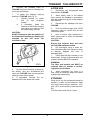
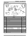
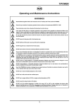
TORNADO T/A/LINE/SCOTT
Operating and Maintenance Instructions
WARNINGS
Before using this equipment, read the contents of EN 529 : 2005 and familiarise yourself with the
requirements for respiratory protective devices and their potential effects on the wearer.
TORNADO respiratory protection systems are designed for use by personnel who are familiar with
workplace hazards.
This Manual must be read in conjunction with the User Manual for the TORNADO headtop used with
T/A/LINE.
Air supplied by the airline system must conform to EN 12021 : 1999 for composition and permissible upper
limit of the following contaminants: Oil, Carbon Dioxide, Carbon Monoxide and moisture. Do not supply
any other gas such as Oxygen, Nitrogen, Carbon Monoxide etc, and ensure connection points are properly
marked. Use of any other gas apart from breathing-quality air may result in death.
Airline systems used to supply T/A/LINE must be fitted with a pressure relief valve.
DO NOT use when ambient oxygen content is less than 19.5% or greater than 23%. There is an increased
fire risk as the oxygen content increases.
Air for compressed airline respiratory protection devices must have a dew-point sufficiently low to prevent
condensing and freezing.
Where apparatus is used and stored at a known temperature the pressure dew-point must be at least 5°C
below the likely lowest temperature. Where conditions of use and storage of the compressed air supply is
not known, the pressure dew-point must not exceed -11°C.
DO NOT use equipment that is damaged or has passed its service-due date. A monthly inspection of the
apparatus is a mandatory requirement in the UK under COSHH regulations and inspection on a monthly
basis is strongly recommended for all other countries.
DO NOT use if the filter warning panel is discoloured. The filter warning panel must be white.
DO NOT use if contaminant levels are likely to be immediately dangerous to life or health.
The equipment may not provide adequate protection in certain highly-toxic atmospheres.
DO NOT use if the ambient temperature is outside of the range -15°C to +60°C. Humidity levels up to 95%
RH do not present any operational problems.
If accessories (for example a spray gun) are to be driven from the same compressed air supply tube, the
User should ensure that at least the minimum flow conditions are present in the equipment when the
accessory is consuming its maximum air-flow requirement.
1
TORNADO T/A/LINE/SCOTT
INTRODUCTION
T/A/LINE is a waistbelt-mounted pressure
regulator for use with a medium-pressure,
light-duty airline system in conjunction
with specific headtops within the
TORNADO range. Please refer to your
headtop User Manual for applicability
details.
This product should only be used where
the risk of damage to the compressed air
supply tube is low and where movement
of the wearer is limited.
Fig. 1
The host airline system must be capable
of delivering a minimum of 140 litres per
minute and a maximum of 200 litres per
minute, at between 2.5 and 7.0 bar.
T/A/LINE is approved for use with SCOTT
airline supply hoses of up to 10m in
length, with a working pressure of 15 bar.
Hoses are available in PVC and antistatic material. Anti-static hoses must be
used
in
flammable
or
explosive
atmospheres. All hoses are approved to
EN 1835.
1.
Combined Filter and Quick-fit
Connector for Headtop Hose.
2.
Warning Panel.
3.
CEJN Airline Hose Coupling.
4.
1/4 BSP Outlet for Power Tool.
OPERATING
1.
Check that T/A/LINE is clean, that
the filter indicator is not discoloured
(indicating that the filter is not
contaminated) and that the unit is fully
serviceable. Replace worn or damaged
parts as necessary.
WARNING:
Ensure that the length of supply hose
selected is sufficient for the task being
undertaken. DO NOT join airline supply
hoses together in order to give a
required length.
2.
Connect the airline to the CEJN
coupling on T/A/LINE and fit the flow-test
indicator to the quick-fit connector on the
filter outlet. Check that the float rises so
that the ‘TM‘ line is visible (see Fig. 2).
T/A/LINE is CE marked and approved to
EN 1835.
The following features are incorporated
within the T/A/LINE unit (see Fig. 1):
•
A replaceable filter that removes
particles and oil vapour from the air
supply.
•
A quick-fit connector on the filter
outlet
that
facilitates
rapid
connection of the headtop air
supply hose.
•
A low-pressure warning whistle that
sounds when the airline fails to
supply
the
minimum
airflow
required.
•
A CEJN airline hose coupling.
•
A 1/4 BSP outlet that provides
power to air-driven power tools.
Fig. 2
3.
Remove the flow-test indicator and
store safely for future use.
4.
Don the waistbelt so that the
T/A/LINE is on the hip and adjust for a
comfortable fit.
5.
Follow the instructions in the
TORNADO headtop User Manual to
inspect and don the headtop.
2
TORNADO T/A/LINE/SCOTT
6.
Connect the headtop hose to
T/A/LINE and check there is a steady flow
of air into the headtop.
AFTER USE
1.
Disconnect any air-powered tools
connected to T/A/LINE.
7.
To adjust the left/right wearing
position of T/A/LINE (see Fig. 3):
i)
Release screws (1), rotate
disc (2) and re-tighten
screws.
ii)
If necessary, swap the
location of the CEJN coupling
and power tool outlet so that
the hoses hang correctly.
2.
When safely clear of the hazard
area, remove the headtop in accordance
with the instructions given in the headtop
User Manual.
3.
Disconnect the headtop hose from
T/A/LINE.
4.
Push the airline supply hose CEJN
connector collar to unlock and pull the
connectors apart.
CAUTION:
DO NOT attempt to alter the position of
the inlet/outlet manifold by rotating the
manifold as this will cause the
manifold to leak.
5.
Use a lint-free cloth moistened in
warm soapy water to clean the waistbelt
and outer case.
CAUTION:
Ensure that moisture does not enter
the T/A/LINE waistbelt module.
6.
Dry thoroughly using a clean lintfree, absorbent cloth and inspect for wear
or damage. Replace any worn or
damaged parts.
7.
Check that the filter indicator is not
discoloured. If signs of discolouration are
evident, the filter MUST be replaced.
WARNING:
The filter and bonded seal MUST be
replaced after six months in service,
regardless of condition.
Fig. 3
8.
Ensure that the airflow required by
the wearer, plus any air-powered tool
used with T/A/LINE does not exceed the
capacity of the airline system.
8.
When completely dry, store in a
cool, clean environment, away from direct
sunlight and radiant heat.
9.
If applicable, connect the airpowered tool to the power tool outlet.
STORAGE
When not in use the equipment should be
stored in a clean, dry environment, away
from direct heat sources between -10ºC
and +30ºC, at a humidity of less than 65%
RH.
The filter has a shelf-life of 5 years.
3
TORNADO T/A/LINE/SCOTT
MAINTENANCE
RECORD INSPECTION AND
MAINTENANCE DETAILS
Inspect T/A/LINE before and after each
occasion of use and check that the plastic
body and connectors are not damaged or
excessively worn. Replace worn or
damaged parts as necessary.
Record test and maintenance details on
the Inspection and Maintenance Record
Sheet provided at the back of this
Manual.
During pre and post-use inspections,
check that the filter indicator is not
discoloured and that the unit is fully
serviceable. If signs of filter discolouration
are evident, the filter MUST be replaced.
Information recorded usually includes:
•
Name of employer responsible for
the apparatus.
•
Make,
model
number
or
identification mark of the apparatus,
together with a description of any
distinguishing features, sufficient to
enable clear identification.
•
Date
of
the
inspection/
maintenance together with the
name,
signature
or
unique
authentication
mark
of
the
examiner.
•
Condition of the apparatus, details
of any defects found and any
remedial action taken.
WARNING:
The filter and bonded seal MUST be
replaced after six months in service,
regardless of condition.
Perform a flow-test as detailed in the
Operating section of this Manual. If the
unit fails the flow-test, use a mediumpressure gauge to check that the
pressure is between 2.5 and 7.0 bar at
the wearer end of the airline.
Service and clean the headtop as
described in the appropriate User Manual.
4
TORNADO T/A/LINE/SCOTT
SPARE PARTS
Item No.
Description
1
Filter Body and Bonded Seal
2
Bonded Seal
3
Whistle Assembly
Part No.
T/AL/FILTER
(Pack of 5)
1027821
2003697
4
Y-piece Connector
-
5
CEJN Hose Coupling
1019325
6
Plug and O-Ring
-
7
Waistbelt
ECWB
8
Backplate Assembly
-
9
Screw
-
10
Regulator Assembly
-
11
Rear Cover
-
12
Screw
-
13
Front Cover
-
14
Top Cover
15
15
15
15
Airline Hose (PVC) - CEJN Couplings
Airline Hose (PVC) - CEJN Couplings
Airline Hose (Anti-static) - CEJN Couplings
Airline Hose (Anti-static) - CEJN Couplings
(3 Metres Long)
(10 Metres Long)
(3 Metres Long)
(10 Metres Long)
HOSE PVC 3M
HOSE PVC 10M
HOSE-AS-3M
HOSE-AS-10M
-
Loctite 542 Hydraulic Sealant
(50 cc)
1034526
-
Loctite 403 Adhesive
(50 g)
2004742
-
PTFE Tape
(12 Metre Roll)
2009625
-
Flow-test Indicator
PPFI92/ASSY/TOR
-
Medium-pressure Gauge
2001750
5
TORNADO T/A/LINE/SCOTT
FITTING SPARES
To Replace the Filter:
1.
Press the release tab (arrowed in
Fig. 4) to unlock the filter.
Fig. 4
7.
Withdraw the regulator unit from the
rear cover. Place rear cover aside.
2.
Unscrew the filter plastic body and
discard.
8.
Remove the seating washer from
the regulator unit and place aside.
3.
Screw the new filter into the
T/A/LINE body until finger-tight, taking
care to ensure that the filter warning
indicator is visible.
4.
9.
Securely clamp the regulator unit,
(by the two flats below the whistle
housing), in a vice.
Re-fasten the release tab.
CAUTION:
DO NOT apply excessive clamping
force to the vice.
To Replace the Whistle:
1.
Remove the filter as described
above. Place aside or discard.
2.
Pull the waistbelt clear of the
backplate
and
using
a
Bladed
Screwdriver, remove the two screws that
secure the backplate to the rear cover.
Place screws aside.
3.
Align the enlarged ends of the slots
in both the backplate and metal support
plate with the locating pegs on the rear
cover and withdraw the backplate
assembly.
4.
Using a Torx Screwdriver, remove
the six screws that secure the rear cover
to the front cover. Place screws aside.
5.
Withdraw the front and top covers
from the unit and place aside.
10. Use an 18mm A/F Spanner to
remove the whistle assembly from the
whistle
housing.
Discard
whistle
assembly.
6.
Unscrew the retaining ring that
secures the regulator unit to the rear
cover, using finger-pressure ONLY. Place
retaining ring aside.
11. Thoroughly clean the threads inside
the whistle housing to remove all traces of
hydraulic sealant and any debris or dirt
that may be present.
CAUTION:
DO NOT use an Adjustable Spanner,
Mole-grips or other similar tools to
remove the retaining ring.
12. Apply ONE drop of Loctite 542
hydraulic sealant to the threads on the
replacement whistle assembly.
13. Screw the replacement whistle
assembly into the whistle housing until
finger-tight.
6
TORNADO T/A/LINE/SCOTT
Fully secure using 18mm A/F Spanner.
DO NOT over-tighten.
To Replace the Hose Coupling:
1.
Remove the regulator unit from the
rear cover as described in operations 1 to
8 in To Replace the Whistle.
Note:
The replacement whistle is pre-set to the
correct operating pressure and therefore
no further adjustment is required.
2.
Securely clamp the regulator unit,
(by the Y-piece connector), in a vice.
14. Taking care to ensure that the
seating washer is correctly positioned on
the regulator, locate the regulator unit into
position on the rear cover.
CAUTION:
DO NOT apply excessive clamping
force to the vice.
3.
Use a 14mm A/F Spanner to
remove the hose coupling from the Ypiece connector. Discard hose coupling.
15. Apply TWO drops of Loctite 403
o
adhesive (180 apart) to the threads on
the regulator.
4.
Thoroughly clean the threads inside
the Y-piece connector to remove all
traces of PTFE Tape and any debris or
dirt that may be present.
16. Secure the regulator unit in position
with the retaining ring, using fingerpressure ONLY. DO NOT over-tighten.
CAUTION:
•
DO NOT use an Adjustable
Spanner, Mole-grips or other
similar tools to re-fit the retaining
ring.
•
Ensure that the regulator unit is
correctly seated within the rear
cover before proceeding further.
5.
Wrap approximately 100mm of
PTFE Tape around the threads on the
replacement hose coupling.
6.
Screw the replacement hose
coupling into the Y-piece connector until
finger-tight. Fully secure using a Torque
Wrench, tightening to a torque of 20 Nm.
7.
Remove the regulator unit from vice
and re-assemble the T/A/LINE unit as
described in operations 14 to 21 in To
Replace the Whistle.
17. Assemble the front and top covers
to the rear cover and secure in position
with the six screws. Tighten the screws
evenly until hand-tight. DO NOT overtighten.
To Replace the Waistbelt:
18. Align the enlarged ends of the slots
in both the backplate and metal support
plate with the locating pegs on the rear
cover and locate the backplate assembly
onto the rear cover.
1.
Undo the belt buckle and slide the
free end of the belt through the male half
of the buckle.
19. Align the two fixing
the backplate and metal
with the threaded holes in
and secure in position
screws.
3.
Fit the new belt through the slots in
the backplate and re-attach through the
male half of the buckle.
2.
Slide the belt fully through the slots
in the backplate. Discard waistbelt.
holes in both
support plate
the rear cover
with the two
20. Tighten the screws evenly until
hand-tight. DO NOT over-tighten.
21. Re-position the waistbelt through
the belt loops on the backplate and re-fit
or renew the filter as described above.
Note:
Before T/A/LINE is re-introduced into
service it may be necessary to adjust the
wearing position, as described within the
Operating section of this Manual.
7
TORNADO T/A/LINE/SCOTT
WARRANTY
NOTIFIED BODIES
The products manufactured at our
factories in Skelmersdale and Vaasa
carry a warranty of 12 months (unless
stated otherwise) for parts, labour and
return to site. The warranty period runs
from the date of purchase by the end
user.
Inspec International Limited (0194)
56 Leslie Hough Way,
Salford,
Greater Manchester,
M6 6AJ,
England.
British Standards Institute (0086)
389 Chiswick High Road,
London,
W4 4AL,
England.
These products are warranted to be free
from
defects
in
materials
and
workmanship at the time of delivery.
SCOTT will be under no liability for any
defect arising from wilful damage,
negligence, abnormal working conditions,
failure
to
follow
the
original
manufacturer’s instructions, misuse or
unauthorised alteration or repair.
Evidence of purchase date will need to be
provided for any claims arising during the
warranty period. All warranty claims must
be directed through SCOTT Customer
Services and in accordance with our
sales return procedure.
8