1
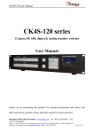
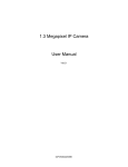
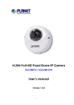
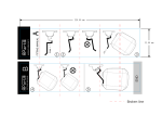
1.3 Megapixel
Compact IP
Dome Camera
User’s Manual
Ver1.4
Table of Contents
1.
2.
Software Version ........................................................................................................3
Introduction.................................................................................................................4
2.1
Features.............................................................................................................4
2.2
Package Contents..............................................................................................5
2.3
Camera Overview ..............................................................................................5
3.
Preparations for IP Camera Setup ............................................................................7
3.1
System Requirements........................................................................................7
3.2
Ethernet Connection ..........................................................................................7
4.
5.
Accessing Camera .....................................................................................................9
Configuration & Operation.......................................................................................16
5.1
Browser-based Viewer Introduction .................................................................16
5.2
Home Page ......................................................................................................18
5.3
System Related Settings..................................................................................19
5.3.1
Host Name and System Time Setting................................................20
5.3.2
Security..............................................................................................21
5.3.3
Network .............................................................................................23
5.3.4
DDNS ................................................................................................26
5.3.5
Mail ....................................................................................................27
5.3.6
FTP....................................................................................................28
5.3.7
Motion Detection................................................................................29
5.3.8
Snapshot ...........................................................................................31
5.3.9
Iris Adjustment (Box Camera and Vandal Proof Dome).....................32
5.4
5.5
5.3.10 View Log File .....................................................................................33
5.3.11 View User Information .......................................................................34
5.3.12 View Parameters ...............................................................................36
5.3.13 Factory Default ..................................................................................37
5.3.14 Software Version ...............................................................................38
5.3.15 Software Upgrade..............................................................................39
Video and Audio Streaming Settings ...............................................................42
5.4.1
Video Resolution and Rotate Type ....................................................42
5.4.2
Video Compression ...........................................................................44
5.4.3
Video OCX Protocol...........................................................................45
5.4.4
Video Frame Skip ..............................................................................46
5.4.5
Privacy Masking Function..................................................................47
5.4.6
Audio Setting .....................................................................................49
Camera Settings ..............................................................................................50
5.5.1
Exposure Setting ...............................................................................50
5.5.2
White Balance Setting .......................................................................51
1
5.6
5.5.3
Backlight Setting ................................................................................52
5.5.4
Brightness Setting..............................................................................52
5.5.5
Sharpness Setting .............................................................................53
5.5.6
Contrast Setting .................................................................................53
5.5.7
Digital Zoom Setting ..........................................................................53
Logout ..............................................................................................................54
6. CMS Software Introduction......................................................................................55
Appendix A: Technical Specifications ...........................................................................56
Appendix B: Internet Security Settings .........................................................................58
Appendix C: DC Viewer Download Procedure ..............................................................61
2
1.
Software Version
The Compact IP Dome Camera’s current software version is as follows:
Time Released
Version
Oct., 2012
p20091016PS
3
2.
Introduction
The 1.3 Megapixel Compact IP Dome Camera features a 1/3.8” Sony
Progressive CMOS Sensor and generates excellent image quality. Having
excellent high definition image quality in low-light conditions, this camera could
identify the individuals and objects of interest easily.
With Power over Ethernet (IEEE 802.3af) feature, the need of power outlets
could be totally eliminated; likewise installation and cabling cost would be
significantly reduced.
The IP Dome Camera’s flat and sophisticated design enhances more
application possibilities, such as indoor/outdoor and mobile surveillance.
Additionally, its light weight and compact size offer quick and simple installation
on the ceilings or walls of houses and vehicles.
2.1
Features
• 1/3.8” 1.3M progressive CMOS
• Simultaneous MPEG-4 and MJPEG video stream (dual stream)
• Resolution: MPEG-4 VGA,QVGA,CIF,QCIF
MJPEG 1280 x 960(4 VGA), VGA, QVGA, CIF, QCIF
• Frame Rate: MPEG-4 30fps@VGA; MJPEG 15fps@1280 x 960
• Image Setting:
Rotation: Flip, Mirror, and 180∘Rotate
Brightness, Sharpness, Contrast, White Balance, Exposure Control
Digital Zoom: x1 ~ x12
• Audio Compression: G.711 PCM 64 kbit/s
G.726 ADPCM 32 or 24 kbit/s
•
•
•
•
4
Shutter Speed: 1.5~1/15000 sec
Interface: 10/100 Ethernet
Compact Size Dome Cover and Housing
Power over Ethernet
2.2
Package Contents
Please check the package contains the following items listed below.
Security Torx
Indoor Camera/
Rugged Camera (with Cable )
Quick Guide
2.3
CD
Camera Overview
Designation
Description
1
Reset Button
Restore to default setting; press the
button with a proper tool
2
Lens
Rotate the lens right/left to adjust focus
3
Focus Fixed Screw
Loosen the screw to adjust the lens
4
Tilt Fixed Screw
Loosen the screw to adjust tilt angle
5
Dimensions
6
3.
Preparations for IP Camera Setup
This chapter outlines information about system requirements for IP Dome
Camera operation, power and Ethernet connection for Indoor/Outdoor IP Dome
Camera, and access to the camera.
3.1
System Requirements
To perform the IP Dome Camera via web browser, please ensure your PC is in
good network connection, and meet system requirements as described below.
Items
Minimum Requirement
1. Intel Pentium IV, 3 GHz or higher, Intel Core2 Duo, 2
Personal Computer
GHz or higher
2. 1 GB RAM or more
3. AGP graphics card 64 MB RAM, Direct Draw
3.2
Operating System
Windows VISTA or Windows XP
Web Browser
Microsoft Internet Explorer 6.0 or later
Network Card
10Base-T (10 Mbps) or 100Base-TX (100 Mbps) operation
Viewer
ActiveX control plug-in for Microsoft IE
Ethernet Connection
Please follow the instructions below to connect Indoor/Rugged IP Dome
Camera’s Ethernet cable.
Indoor Camera
PoE Connection
Connect the one end of the PoE cable to the Ethernet port on the camera,
and the other end to Power Sourcing Equipment (PSE) like hubs or routers.
7
Check the status of the link indicator and activity indicator LEDs; if the LEDs
are unlit, please check the connections.
Green Link Light indicates good network connection.
Orange Activity Light flashes for network activity indication.
Rugged Camera
M12 D-Coded Connector
PoE Waterproof Switch
M12 D-Coded Connection
For the Rugged IP Dome Camera, connect its Ethernet cable to a M12
waterproof switch as shown above.
NOTE: Please use a PoE waterproof switch/hub so that the camera
can work.
M12 D-Coded Connector’s Pin Definition
Pin 1: Rx+
Pin 2: Tx+
Pin 3: Rx-
Pin 4: Tx-
8
4.
Accessing Camera
For initial access to the IP Dome Camera, users can search the camera through
the installer program: DeviceSearch.exe, which can be found in “DeviceSearch”
folder in the supplied CD.
Device Search Software Setup
Step 1: Double click on the program Device Search.exe (see the icon below);
its window will appear as shown below. Then click the “Device Search”
button.
Step 2: The security alert window will pop up. Click “Unblock” to continue.
9
Device Search
Step 3: Click “Device Search” again, and all the finding IP devices will be listed
in the page, as shown in the figure below. The IP Dome Camera’s
default IP address is: 192.168.0.250.
Step 4: Double click or right click and select “Browse” to access the camera
directly via web browser.
Step 5: Then the prompt window of request for entering default username
and password (as shown below) will appear for logging in to the IP
Dome Camera.
10
The default login ID and password for the Administrator are:
Login ID
Password
Admin
1234
NOTE: ID and password are case sensitive.
NOTE: It is strongly advised that administrator’s password be
altered for the security concerns. Refer to section 5.3.2 Security
for further details.
Additionally, users can change the IP Dome Camera’s network property, either
DHCP or Static IP directly in the device finding list. Refer to the following section
for changing the IP Dome Camera’s network property.
Example of Changing IP Dome Camera’s Network Property
Users can directly change an IP Dome Camera’s network property, ex. from
static IP to DHCP, in the finding device list. The way to change the IP Dome
Camera’s network property is specified below:
Step 1: In the finding device list, click on the IP Dome Camera that you would
like to change its network property. On the selected item, right click and
select “Network Setup.” Meanwhile, record the IP Dome Camera’s
MAC address, for future identification.
Step 2: The “Network Setup” page will come out. Select “DHCP,” and press
“Apply” button down the page.
11
Step 3: Click “OK” on the Note of setting change. Wait for one minute to
re-search the IP Dome Camera.
Step 4: Click the “Device Search” button to re-search all the devices. Then
select the IP Dome Camera with the correct MAC address. Double click
on the IP Dome Camera, and the login window will come out.
12
Step 5: Enter User name and Password to access the IP Dome Camera.
Installing DC Viewer Software Online
For the initial access to the IP Dome Camera, a client program, DC Viewer, will
be automatically installed to your PC when connecting to the IP Dome Camera.
If the Web browser doesn’t allow DC Viewer installation, please check the
Internet security settings or ActiveX controls and plug-ins settings (see
Appendix B: Internet Security Settings) to continue the process.
The Information Bar (just below the URL bar) may come out and ask for
permission to install the ActiveX Control for displaying video in browser (see the
figure below). Right click on the Information Bar and select “Install ActiveX
Control…” to allow the installation.
13
Then the security warning window will pop up. Click “Install” to carry on software
installation.
Click “Finish” to close the DC Viewer window when download is finished. For
the detailed software download procedure, please refer to Appendix C: DC
Viewer Download Procedure.
Once login to the IP Dome Camera, users will see the Home page as shown
below:
Administrator/User Privileges
“Administrator” represents the person who can configure the IP Dome Camera
and authorize users access to the camera; “User” refers to whoever has access
to the camera with limited authority, i.e. entering Home and Camera setting
pages.
Lens Adjustment
The image displays on the Home page when successfully accessing to the IP
Dome Camera. Adjust the camera’s focus to produce a clear image. Please
refer to the procedure below.
14
Step 1: Unscrew the IP Dome Camera’s cover.
Step 2: Loosen the focus fixed screw, and rotate the lens counter-/clockwise to
adjust focus; loosen the tilt fixed screw, and adjust the camera’s tilt
angle.
15
5.
Configuration & Operation
The IP Dome Camera is provided with a user-friendly browser-based
configuration interface, and a free bundled CMS (Central Management System)
for record and playback video. In this chapter, information about main page
introduction, system related settings and camera settings will be described in
detail.
For further information about CMS software, please refer to Chapter 6. CMS
Software Introduction and CMS user manual.
5.1
Browser-based Viewer Introduction
The figure below shows the main page of the IP Dome Camera user interface.
At the bottom of the main page, users can adjust video display size (x1, x1/2
and full screen), select a kind of video format (MPEG-4 and MJPEG) and save
MJPEG snapshots (see 5.3.8 Snapshot).
16
There are five tabs: Home, System, Streaming, Camera and Logout on the top
panel.
Home
Users can monitor live video of the targeted area.
System setting
Administrator can set host name, system time, root password, network related
settings, etc. Further details will be interpreted in section 5.3 System Related
Settings.
Streaming setting
Administrator can modify video resolution and rotate type and select audio
compression mode in this page.
Camera setting
Users can adjust various camera parameters, including <Exposure>, <White
Balance>, <Brightness>, <Sharpness>, <Contrast> and <Digital Zoom>.
Logout
Click on the tab to relogin the IP Dome Camera with another username and
password.
17
5.2
Home Page
In the Home page, there are several function buttons right down the displayed
image.
Screen Size Adjustment
Image display size can be adjusted to x1/2 and full screen.
Digital Zoom Control
In the full screen mode, users can implement digital PTZ by right clicking the
mouse, rotating the mouse wheel (for zoom in/out), and drag the mouse into
any direction.
Snapshot
Press the button, and the MJPEG snapshots will automatically be saved in the
appointed place. The default place of saving snapshots is: C:\.
18
5.3
System Related Settings
The figure below shows all categories under the “System” tab. Each category in
the left column will be explained in the following sections.
NOTE: The “System” configuration page is only accessible by
Administrator.
19
5.3.1
Host Name and System Time Setting
Press the first category: <System> in the left column; the page is shown as
below.
Host Name
The name is for camera identification. If Motion Detection function (see 5.3.7
Motion Detection) is enabled and is set to send alarm message by Mail/FTP, the
host name entered here will display in the alarm message.
Sync With Computer Time
Select the item, and video date and time display will synchronize with the PC’s.
Manual
The Administrator can set video date, time and day manually. Entry format
should be identical with that shown next to the enter field.
20
5.3.2
Security
Click the category: <Security>, and the page is shown as the figure below.
Root password
Change the administrator’s password by inputting the new password in both text
boxes. The input characters/numbers will be displayed as dots for security
purposes. After clicking <Save>, the web browser will ask the Administrator for
the new password for access. The maximum length of the password is 14 digits.
NOTE: The following characters are valid: A-Z, a-z, 0-9, !#$%&’-.@^_~.
Add user
Type the new user's name and password and click <Add> to add the new user.
Both user name and password can be up to 16 characters. The new user will be
displayed in the user name list. There is a maximum of twenty user accounts.
Each user can be assigned the privileges of “Camera control” and/or
“Listen”.
21
•
I/O access
This item supports fundamental functions that enable users to view
video when accessing to the camera.
•
Camera control
This item allows the appointed User to change camera parameters on
the Camera Setting page.
•
Talk/Listen
Talk and Listen functions allow the appointed user in the local site (PC
site) communicating with, for instance, the administrator in the remote
site.
NOTE: The IP Mini Fixed Dome Camera does not have Talk
function.
Manage User
Delete user
To delete a user, pull down the user list, and select the user name you wish to
delete. Then click <Delete> to remove it.
Edit user
Pull down the user list and select a user name. Click <Edit> to edit the user’s
password and privilege.
NOTE: It is required to enter the User password as well as select the
function open to the user. When finished, click <Save> to modify the
account authority.
22
NOTE: The Compact IP Dome Camera does not have Talk function.
5.3.3
Network
Click <Network> in the left column, and the page will display as shown below.
23
Users can choose to use fixed IP address or dynamic (DHCP) IP address. The
following is descriptions for the two ways of setting IP address.
Get IP address automatically (DHCP)
The camera’s default setting is “Use fixed IP address”. Please refer to the
previous section Chapter 4. Accessing Camera for logging in with the default IP
address.
If select “Get IP address automatically”, after the IP Dome Camera restarts,
users can search it through the installer program: DeviceSearch.exe, which can
be found in “DeviceSearch” folder in the supplied CD.
NOTE: Please make the record of the IP Dome Camera’s MAC address,
which can be found in the label of the camera, for identification in the
future.
Use fixed IP address
To setup static IP address, select “Use fixed IP address” and move the cursor
to the IP address blank (as indicated below) and insert the new IP address, ex.
192.168.7.234; then go to the Default gateway (explained latter) blank and
change the setting, ex. 192.168.7.254. Press “Save” to confirm the new setting.
24
When using static IP address to login to the IP Dome Camera, users can access
it either through “DeviceSearch” software (see Chapter 4. Accessing Camera)
or input the IP address in the URL bar and press “Enter”.
General
•
IP address
This is necessary for network identification.
•
Subnet mask
It is used to determine if the destination is in the same subnet. The
default value is “255.255.255.0”.
•
Default gateway
This is the gateway used to forward frames to destinations in different
subnet. Invalid gateway setting will fail the transmission to destinations
in different subnet.
•
Primary DNS
Primary DNS is the primary domain name server that translates
hostnames into IP addresses.
•
Secondary DNS
Secondary DNS is a secondary domain name server that backups the
primary DNS.
•
Web Server port
Web server port could be set from 1 to 65535.
Advanced
•
RTSP port
RTSP port could be set from 1 to 65535. (Normal Setting Port: 554,
1024 ~65535)
NOTE: Be aware to choose the different port from the one set for the
web server port.
25
5.3.4
DDNS
Dynamic Domain Name System (DDNS) allows a DNS name to be constantly
synchronized with a dynamic IP address. In other words, it allows those using a
dynamic IP address to be associated to a static domain name so others can
connect to it by name.
Enable DDNS
Check the item to enable DDNS.
Provider
Select one DDNS host from the provider list.
Host name
Enter the registered domain name in the field.
Username/E-mail
Enter the username or e-mail required by the DDNS provider for authentication.
26
Password/Key
Enter the password or key required by the DDNS provider for authentication.
5.3.5
Mail
The Administrator can send an e-mail via Simple Mail Transfer Protocol (SMTP)
when motion is detected. SMTP is a protocol for sending e-mail messages
between servers. SMTP is a relatively simple, text-based protocol, where one or
more recipients of a message are specified and the message text is transferred.
The configuration page is shown as follows:
Two sets of SMTP can be configured. Each set includes SMTP Server, Account
Name, Password and E-mail Address settings. For SMTP server, contact your
network service provider for more specific information.
27
5.3.6
FTP
The Administrator can set as sending alarm message to a specific File Transfer
Protocol (FTP) site when motion is detected. Users can assign alarm message
to up to two FTP sites. The FTP setting page is shown below. Enter the FTP
details, which include server, server port, user name, password and remote
folder, in the fields. Press “Save” when finished.
28
5.3.7
Motion Detection
Motion Detection function allows detecting suspicious motion when motion
volume in the detected area reaches/exceeds the determined sensitivity
threshold value.
Active Motion Detection
You will be able to turn on/off Motion Detection in System section. Default
setting is Off.
Motion Detection Setting
Users could adjust the parameter and level of Motion Detection Settings.
•
•
•
•
Sampling pixel interval [1-100]: Default value: 10
Detection level [1-100]: Default value: 10
Sensitivity level [1-100]: Default value: 80
Time interval (sec) [0-7200]: Default value: 10
29
Alternative actions to motion can be selected.
Send E-mail when the motion detected
Once motion is detected, the system could automatically send a notice to user’s
E-mail address.
Send message to FTP when motion detected
The message will be sent to FTP site which administrator sets when motion is
detected.
NOTE: Make sure SMTP or FTP configuration has been completed. See
section 5.3.5 Mail and 5.3.6 FTP for further details.
30
5.3.8
Snapshot
The IP Dome Camera supports MJPEG snapshot function. Users can specify a
storage location for the snapshots. The default setting is: C:\. Once confirm the
setting, press “Save,” and all the snapshots will be saved in the designate
location.
NOTE: If the specified file folder is indicated as invalid, please check its
name and ensure it not containing characters such as spaces.
31
5.3.9
Iris Adjustment (Box Camera and Vandal Proof Dome)
Users could adjust auto iris lens when different lens is selected to install on the
camera. The iris adjustment page is shown below.
Please follow the steps below to adjust iris.
Step 1: Check if the auto iris lens is set up ready.
Step 2: Image a gray scale chart type 1(Gamma = 1) over the entire screen.
Step 3: Press “Start” button and began to adjust iris.
32
5.3.10 View Log File
Click on the link to view the system log file. The content of the file provides
useful information about configuration and connections after system boot-up.
33
5.3.11 View User Information
The Administrator can view each added user’s login information and privileges
(see 5.3.2 Security).
View User Login Information
All the users in the network will be listed in the “User information” zone, as
shown below. As the figure below shows:
User: 4321
It indicates that one user’s login username is: User, and the password is: 4321.
View User Privilege
Press “get user privacy” down the page, and the Administrator can view each
user’s privileges.
34
As the figure above shows:
User: 1:1:0:1
1:1:0:1= I/O access : Camera control : Talk : Listen (see 5.3.2 Security)
Therefore, it denotes the user is granted privileges of I/O access, Camera
control and Listen.
35
5.3.12 View Parameters
Click on this item to view the entire system’s parameter setting.
36
5.3.13 Factory Default
The factory default setting page is shown as below. Follow the instructions to
reset the IP Dome Camera to factory default setting if needed.
Set Default
Click on the “Set Default” button to recall the factory default settings. Then the
system will restart in 30 seconds.
NOTE: The IP address will be restored to default.
Reboot
Click on the “Reboot” button, and the system will restart without changing
current settings.
37
5.3.14 Software Version
The current software version is displayed in the software version page, which is
shown as the figure below.
38
5.3.15 Software Upgrade
Software upgrade can be carried out in the “Software Upgrade” page, as shown
below.
NOTE: Make sure the upgrade software file is available before carrying
out software upgrade.
The procedure of software upgrade is like the following:
Step 1: Click “Browse” and select the binary file to be uploaded, ex.
Userland.jffs2.
39
NOTE: Do not change the upgrade file name, or the system will fail to
find the file.
Step 2: Pull down the upgrade binary file list and select the file you want to
upgrade; in this case, select “userland.jffs2.”
Step 3: Press “Upgrade”. The system will first check whether the upgrade file
exists or not, and then begin to upload the upgrade file. Subsequently,
the upgrade status bar will display on the page. When it runs to 100%,
the upgrade process is finished.
40
After the upgrade process is finished, the viewer will return to Home page, and
operation can continue.
41
5.4
Video and Audio Streaming Settings
Press the tab ”Streaming” in the top of the page, and the configurable video and
audio items will display in the left column. In Streaming, the Administrator can
configure specific video resolution, video compression mode, video protocol,
audio transmission mode, etc. Further details of these settings will be specified
in the following sections.
5.4.1
Video Resolution and Rotate Type
The video setting page is shown below:
Video Resolution
The IP Dome Camera provides various video dual streaming formats like the
following:
• MJPEG 1280×960 (15fps) + MPEG-4 VGA (15fps)
• MJPEG 1280×960 (15fps) + MPEG-4 QVGA (15fps)
• MJPEG 1280×960 (15fps) + MPEG-4 CIF (15fps)
• MJPEG 1280×960 (15fps) + MPEG-4 QCIF (15fps)
• MJPEG 1280×960 (15fps) + MPEG-4 Disable
42
•
MJPEG 640×480 (30fps) + MPEG-4 VGA (30fps)
•
MJPEG 640x480 (15fps) + MPEG-4 VGA (15fps)
Click “Save” to confirm the setting.
Video Rotate Type
Users can change video display type if necessary. Selectable video rotate types
include Normal, Flip, Mirror and 180 degree. Differences among these types are
illustrated as below.
Suppose the displayed image of IP Dome Camera is shown as the figure below.
To rotate the image, users can select “Flip”, for instance. Then the displayed
image will be reversed as shown below.
The following is descriptions for different video rotate type.
•
Flip
If select <Flip>, the image will be rotated vertically.
•
Mirror
If select <Mirror>, the image will be rotated horizontally.
43
•
180 Degree
Selecting <180 Degree> will make the image 180° counter-/clockwise
inversed.
Click “Save” to confirm the setting.
5.4.2
Video Compression
Users can select a proper MJPEG/MPEG-4 compression mode in the video
compression page (see the figure below), depending on the application.
MJPEG compression settings include:
•
•
•
high compression, low bitrate, low quality
middle compression, default
low compression, high bitrate, high quality
MPEG-4 compression settings include:
•
•
•
44
128 kbps , highest compression , lowest quality
256kbps , default
512kbps
•
1024kbps , lowest compression , highest quality
Users can also decide whether to display compression information in Home
page.
Click “Save” to confirm the setting.
5.4.3
Video OCX Protocol
In the Video OCX protocol setting page, users can select RTP protocol using
UDP or TCP transport, for streaming media over the network. In the case of
multicast networking, users can select the Multicast mode. The page is shown
as follows.
Video OCX protocol setting options include:
•
RTP over UDP/RTSP(TCP)
Select a mode according to your data delivery requirements.
45
•
Multicast Mode
Enter all required data, including multicast IP address, MPEG-4 video
port, MJPEG video port and audio port, into each blank.
Click “Save” to confirm the setting.
5.4.4
Video Frame Skip
Video frame skipping is for saving bandwidth if necessary. The setting page is
shown as below.
MJPEG/MPEG-4 Frame Skip options include:
•
•
•
•
No skipping, default
Frame skipping at 5 frame internal (lowest frame loss rate)
Frame skipping at 10 frame internal
Frame skipping at 15 frame internal (highest frame loss rate)
NOTE: Higher frame skipping rate will decrease video smoothness.
46
5.4.5
Privacy Masking Function
Users can setup maximum two privacy masks in the selected areas to avoid any
intrusive monitoring. The Mask setting page is shown below:
Help Page
Mask Setup
Select either Mask1 or Mask2 in the section: Active Mask Function, and a red
frame will come out in the displayed image. To shift the red frame (mask) to a
desired position, move the mouse to the center of the frame and then left click
the mouse. As for adjusting the frame size, move the mouse onto the edges of
the frame to change its extent.
The mask(s) can be set with a selected color and type in the section: Mask
Setting. After configure all the settings mentioned previously, click the “Save”
button, and the mask(s) will be displayed as user-defined.
Mask Settings Modification
To reposition/resize a mask, draw its red frame to the new position or adjust the
frame’s size. The mask’s color and type can be reselected as well. Click the
“Save” button, and the rearranged mask will be displayed after few seconds.
47
Mask Cancel
Uncheck either Mask1 or Mask2 or both to cancel the mask(s).
Help Page
A Mask Description page is provided for your reference during privacy mask
setup. Click on the question mark in the upper left corner above the displayed
image (see the arrow in the figure above), and the Mask Description page will
open in a new window, as shown below:
48
5.4.6
Audio Setting
The audio setting page is show as below. In the Audio page, the Administrator
can select one transmission mode and audio bit rate.
Transmission Mode
•
Simplex (Listen only)
In the Listen only Simplex mode, the local/remote site can only listen to
the other site.
•
Disable
Select the item to turn off the audio transmission function.
Bit Rate
Selectable audio transmission bit rate include 16 kbps (G.726), 24 kbps (G.726),
32 kbps (G.726), 40 kbps (G.726), uLAW (G.711) and ALAW (G.711). Both
uLAW and ALAW signify 64 kbps but in different compression formats. Higher
bit rate will let higher audio quality and require bigger bandwidth.
Click “Save” to confirm the setting.
49
5.5
Camera Settings
The figure below is the camera configuration page. Details of each parameter
setting are described as follows.
5.5.1
Exposure Setting
The exposure is the amount of light received by the image sensor and is
determined by the width of lens diaphragm opening (iris adjustment), the
amount of exposure by the sensor (shutter speed) and other exposure
50
parameters. With this item, users can define how the Auto Exposure function
works.
Each exposure mode is specified as follows:
Full Auto Mode
In this mode, the camera’s Shutter Speed, IRIS and AGC (Auto Gain Control)
control circuits work together automatically to get consistent video output level.
Auto Flickerless (50Hz)/(60Hz) Mode
Television scanning (PAL & NTSC) and power supply systems (AC 50 & 60 Hz)
are not the same in different countries and regions. Users might find flickering
situation displayed on the screens because the devices are working under
different frequency systems. With Auto Flickerless function, users could reduce
the symptom.
Manual Mode
In this mode, users can select a number between 1 and 15, which represents
shutter speed ranging from 1/4 to 1/10000 sec; bigger number means slower
shutter. Once change the setting, press <SET> to confirm the new setting.
Fixed Shutter Mode
In this mode, fixed shutter speed could be selected from the draw-down menu.
The range is provided from 1.5 to 1/10000 sec. and total 17 different shutter
speed could be chose Users could select suitable shutter speed based on the
camera environment.
5.5.2
White Balance Setting
A camera needs to find reference color temperature, which is a way of
measuring the quality of a light source, for calculating all the other colors. The
unit for measuring this ratio is in degree Kelvin (K). Users can select one of the
White Balance Control modes according to the operating environment. The
51
following table shows the color temperature of some light sources for reference.
Light Sources
Color Temperature in K
Cloudy Sky
Noon Sun and Clear Sky
Household Lighting
75-watt Bulb
Candle Flame
6,000 to 8,000
6,500
2,500 to 3,000
2,820
1,200 to 1,500
Auto Mode
In this mode, white balance works within its color temperature range and
calculates the best-fit white balance.
Indoor/outdoor Mode
Select for indoor or outdoor mode.
Manual Mode
In this mode, users can change the White Balance value manually. Users can
select a number between 1 ~ 11, and press <SET> to confirm the new setting.
5.5.3
Backlight Setting
Based on various lighting situations, users could select to turn on or off the
function of backlight compensation to optimize the video quality. The default
value of Backlight is Off.
5.5.4
Brightness Setting
Users can adjust the image’s brightness by adjusting the item. To increase
video brightness, select a bigger number. Press <SET> to confirm the new
setting.
52
5.5.5
Sharpness Setting
Increasing the sharpness level can make the image looked sharper; especially
enhance the object’s edge. Press <SET> to confirm the new setting.
5.5.6
Contrast Setting
Camera image contrast level is adjustable; please select ranging from 1 to 11.
5.5.7
Digital Zoom Setting
The camera’s digital zoom is adjustable from x1 to x12 at VGA resolution. Press
<SET> to confirm the new setting.
53
5.6
Logout
Press the tab “Logout” in the top of the page, and the login window will pop up.
This enables login with another user name.
54
6.
CMS Software Introduction
The IP Dome Camera bundles Central Management System (CMS) software.
Offering powerful functionalities via intuitive interface, it is a centralized
monitoring solution of your video surveillance equipments.
It gives the user access to monitor multiple IP Dome Cameras and Digital Video
Recorders (DVRs), and allows the user to simultaneously monitor 64 sites per
group (up to 10 groups) within several clicks.
For further information on CMS software, please refer to the supplied CD.
55
Appendix A: Technical Specifications
Camera
Image Sensor
1/3.8" Sony progressive CMOS
Picture Elements
1280(H) x 960 (V), 1.3M CMOS
Optical
Lens Focal Length
f = 3.6 mm
F Number
F = 2.0
Angle of View
96o
Operation
Video Compression
MPEG-4 / MJPEG
Video Streaming
Simultaneous MPEG-4 and MJPEG video stream (dual
stream)
Resolution
MPEG-4: VGA,QVGA,CIF,QCIF
MJPEG: 1280x960(4VGA), VGA
Horizontal Resolution
>700TVL
Frame Rate
MPEG-4 30fps@VGA, MJPEG 15fps@1280x960
Image Setting
Brightness
manual control
Exposure
auto and manual control mode
Sharpness
manual control
Contrast
manual control
White Balance
Auto, indoor, outdoor, manual control mode
Digital Zoom
1x ~ 12x
Rotation
Flip, Mirror, and 180∘Rotate
Network
Interface
10/100 Ethernet
Protocol
IP, TCP, SMTP, DHCP, HTTP
Password Levels
User and Administrator
Internet Browser
Internet Explorer (6.0+)
Mechanical
Camera Angle Adjustment
Tilt 0-90° ; Pan 0-90°
Connectors
RJ-45 Connector (Indoor Type)
Ethernet
Audio
M12 D-Coding Cable (Rugged Type)
G.711 PCM 64 kbit/s
G.726 ADPCM 32 or 24 kbit/s
General
Operating Temperature
0°C ~ 50°C
Operating Humidity
10% to 90%, no condensation
Power Source
PoE
56
Power Consumption
3W
Regulatory
CE, FCC
Certificate
RoHS compliant
IP66 (Rugged Type Only)
Dimension
W*H*L
107 x 107 x 47 mm (4.2 x 4.2 x 1.9 inches)
57
Appendix B: Internet Security Settings
If ActiveX control installation is blocked, please either set Internet security level to default or
change ActiveX controls and plug-ins settings.
Internet Security Level: Default
Step 1: Start the Internet Explorer (IE).
Step 2: Select <Tools> from the main menu of the browser. Then Click <Internet Options>.
Step 3: Click the <Security> tab, and select <Internet>.
Step 4: Down the page, press “Default Level” (see the figure above) and click “OK” to
confirm the setting. Close the browser window, and open a new one later when
accessing the IP Dome Camera.
58
ActiveX Controls and Plug-ins Settings
Step 1~3: Refer to the previous section above.
Step 4: Down the page, press “Custom Level” (see the figure below) to change ActiveX
controls and plug-ins settings.
The Security Settings screen is displayed as below:
59
Step 5: Under “ActiveX controls and plug-ins”, set ALL items (as listed below) to <Enable>
or <Prompt>.
ActiveX controls and plug-ins settings:
1. Automatic prompting for ActiveX controls
2. Binary and scrip behaviors
3. Download signed ActiveX controls
4. Download using ActiveX controls
5. Initialize and script ActiveX not marked
as safe
6. Run ActiveX controls and plug-ins
7. Script ActiveX controls marked safe for
scripting
Step 6: Click <OK> to accept the settings and close the <Security> screen.
Step 7: Click <OK> to close the Internet Options screen.
Step 8: Close the browser window, and restart a new one later for accessing the IP Dome
Camera.
60
Appendix C: DC Viewer Download Procedure
The procedure of DC Viewer software download is specified as follows.
Step 1: In the DC Viewer installation page, click “Next” for starting installing.
Step 2: Setup starts. Please wait for a while until the loading bar runs out.
61
Step 3: Click “Finish” to close the DC Viewer installation page.
Then, the IP Camera’s Home page will display as follows:
62