1
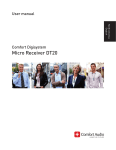
Building Wash
BW-180-RGBW
User Manual
Please read the instructions carefully before use
TABLE OF CONTENTS
1. Safety Instructions.........................................................................................................2
2. Techical Specfications ..................................................................................................3
3. Installation ......................................................................................................................4
4. How To Set The Unit ......................................................................................................4
4.1 Control Panel..........................................................................................................4
5. How To Control The Unit ...............................................................................................4
5.1 Master/Slave Built In Preprogrammed Function .................................................5
5.2 DMX 512 Configuration .........................................................................................5
5.3 Master-Slave Connection ......................................................................................7
6. Troubleshooting.............................................................................................................8
7. Cleaning and Maintenance............................................................................................9
1-
1. Safety Instructions
WARNING
Please read the instructions carefully which includes
important information about the installation, operation
and maintenance.
y Please keep this User Guide for future consultation. If you sell the unit to another user,
be sure that they also receive this instruction booklet.
Caution:
y All units are intact from the manufacturer, please operate follow up the user manual,
artificial fault are not under guarantee repair.
y Unpack and check carefully there is no transportation damage before using the unit.
y Do install and operate by operator.
y Use safety chain when fixes the unit.
y The unit must be installed in a location with adequate ventilation, at least 50cm from
adjacent surfaces.
y Be sure that no ventilation slots are blocked, otherwise the unit will be overheated.
y Before operating, ensure that the voltage and frequency of power supply match the
power requirements of the unit.
y It’s important to ground the yellow/green conductor to earth in order to avoid electric
shock.
y Maximum ambient temperature is 40℃. Don’t operate it where the temperature is
higher than this.
y Don’t connect the device to any dimmer pack.
y First run, there will be smoke or smells, and all disappearing a few minutes later.
y Make sure there are no flammable materials close to the unit while operating, as it is fire
hazard.
y Look over power wires carefully, replace immediately if there is any damage.
y Unit surface temperature may reach up to 85℃. Don’t touch the housing bare-hand
during its operation.
y Never run on for a long time lest shortening lifespan.
y Avoid any inflammable liquids, water or metal objects entering the unit. Once it happen,
cut off the mains power immediately.
y Do not operate in dirty and dusty environment, also cleaning units regularly.
2-
y Do not allow children to operate the unit.
y Do not touch any wire during operation as there might be a hazard of electric shock.
y Avoid power wires together arounding other cables.
y Replace fuse only with the same type.
y In the event of serious operating problem, stop using the unit immediately.
y Never turn on and off the unit time after time.
y The housing, the lenses, or the ultraviolet filter must be replaced if they are visibly
damaged.
y Do not open the unit as there are no user serviceable parts inside. Never try to repair
the unit by yourself. Repairs carried out by unskilled people can lead to damage or
malfunction. Please contact the nearest authorized technical assistance center.
y Disconnect the mains power if the unit is not used for a long time.
y Do use original packing materials once transport it again.
y Do not look directly at the LED light beam while the unit is on.
y To protect the machine, power off 10s rear can electrify.
2. Techical Specfications
y Light source:3W CREE LED x 180pcs(R40, G50, B50, W40)
y Voltage:AC 100-240V/50Hz~60Hz
y Power consumption:600W
y Lens Option:6°, 15°, 25°, 25×45°, 40°, 60°
y IP:66
y Dimension:748X446X422 mm
y Weight:43.1kg
3-
3. Installation
The unit can be placed directly on the stage floor which can support 10 times of the unit’s
weight. Ensure that the stage floor to which you are placing the unit is secure.
Enhanced care has to be considered during the installation.
The equipment must be fixed by professionals.
Note: Range of mounting height is 0~30m.
4. How To Set The Unit
4.1 Control Panel
You must use hand-held controller VD-T (sold separately) for DMX addressing or Channel
mode selection, etc.
①: Power
Water proof connectors for power input.
②: DMX input
Water proof connectors for DMX 512 operation, 3-pin XLR cable to input DMX signal.
③: DMX output
Water proof connectors for DMX 512 operation, 3-pin XLR cable to output DMX signal.
5. How To Control The Unit
You can operate the unit in two ways:
1. By master/slave built-in preprogram function
2. BY VD-T
VD-T is a specially designed handy setup tool for all Visio integral units and Controllers. By
connecting VD-T to any unit via XLR, you can easily setup DMX Address, Channel Modes,
White Balance, Manual Colors, and Fade Speed functions. If you use VD-T to control the
unit, you can follow User Manual of VD-T.
4-
5.1 Master/Slave Built In Preprogrammed Function
By linking the units in master/slave connection, the first unit will control the other units to
give an automatic, synchronized light show. This function is good when you want an instant
show. In Master/Slave mode, the first unit whose DMX input jack has with nothing connect
will be master automatically, set other units to slave mode.
5.2 DMX 512 Configuration
5-
6-
5.3 Master-Slave Connection
1. If you using a controller with 5 pins DMX output, you need to use a 5 to 3 pin
adapter-cable.
2. At last unit, the DMX cable has to be terminated with a terminator. Solder a 120 ohm
1/4W resistor between pin 2(DMX-) and pin 3(DMX+) into a 3-pin XLR-plug and plug it
in the DMX-output of the last unit.
3. Connect the unit together in a `daisy chain` by XLR plug from the output of the unit to
the input of the next unit. The cable can not branched or split to a `Y` cable. DMX 512 is
a very high-speed signal. Inadequate or damaged cables, soldered joints or corroded
connectors can easily distort the signal and shut down the system.
4. The DMX output and input connectors are pass-through to maintain the DMX circuit,
when one of the units’ power is disconnected.
5. Each lighting unit needs to have an address set to receive the data sent by the
controller. The address number is between 0-511 (usually 0 & 1 are equal to 1).
6. The end of the DMX 512 system should be terminated to reduce signal errors.
7. 3 pin XLR connectors are more popular than 5 pin XLR.
3 pin XLR: Pin 1: GND, Pin 2: Negative signal (-), Pin 3: Positive signal (+)
5 pin XLR: Pin 1: GND, Pin 2: Negative signal (-), Pin 3: Positive signal (+), Pin 4/Pin 5:
Not used.
7-
6. Troubleshooting
Following are a few common problems that may occur during operation and some
suggestions for easy troubleshooting:
Problem
The unit does not work, no
light.
Possible Cause
Incorrect power cable
connection.
Action
Check the connection of
power.
Incorrect mains voltage.
Measure the mains voltage
on the main connector.
Incorrect DMX cable
connection.
Check DMX connectors and
cables to see if link properly.
Repair or replace damaged
wires.
Incorrect address assignment Check the addresses of the
to the units.
units and the protocol
settings.
The unit does not respond
Unfinished data connection.
properly to the DMX control.
Insert a terminal plug in the
output jack of the last unit of
the connection.
It has been set up an
Check the operating mode set
operating mode different from up.
the DMX mode used.
Try to use another DMX
controller.
8-
7. Cleaning and Maintenance
DANGER!
Disconnect from the mains before starting any cleaning or maintenance work.
The unit must be cleaned periodically to optimize light output. Cleaning frequency depends
on the environment where the unit will operate: deposits of dust, smokes or other wastes
will reduce the light output performances.
y Clean regularly the glass of the unit with soft cotton towel dampened with a
glass-cleaning liquid or distilled water.
y Wash the housing with a soft brush or sponge and a mild, non-abrasive washing
detergent.
y Remove smoke and other wastes by a cotton towel dampened with isopropyl alcohol.
y Be careful when cleaning the components.
y Always dry the parts carefully by a clean, soft, non-scratching towel or by compressed air.
y Maintenance and service operations are only to be carried out by a qualified person.
9-
Innovation, Quality, Performance
10-