1
V&T Technologies Co., Ltd.
http://www.ecodrivecn.com
TM
Vectorque
V&T FREQUENCY INVERTER ADDITIVE MANUAL
for Injection Molding Machine
V&T
V5-I Series
ADDITIVE MANUAL
V5-I injection molding machine for inverter User's manual
1
V&T Technologies Co., Ltd.
http://www.ecodrivecn.com
Foreword
V5-I series frequency inverter is a kind of professional and high performance vector
control inverter provided by Shenzhen V&T Technologies Co.,Ltd. The products is
special for energy saving in injection molding machine, which adopts speed
sensorless vector control technology, the internationally leading technology,offers
excellent control performance and combines the application characteristics of
Chinese injection machine to further enhance the product reliability, environment
adaptability and customized and industrialized design. It can better meet the
demands of injection machine application.
Please use V5-H universal inverter manual with the additive manual.
V5-I injection molding machine for inverter User's manual
2
V&T Technologies Co., Ltd.
http://www.ecodrivecn.com
1. Change Scope:
Increase digital given stack allows functions;
The lowest carrier frequency down to 0.4K;
Increase the input terminal delay function;
Increase AI1 ~ AI3 support H0 group functions
AI terminal filter time and the the X1X2 terminal delay time factory default modified
2 . Changing function code description
V5-I injection molding machine for inverter User's manual
3
V&T Technologies Co., Ltd.
http://www.ecodrivecn.com
P5.08
X1 terminal delay time
0.0 ~ 999.9s
P5.09
X2 terminal delay time
0.0 ~ 999.9s
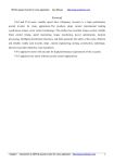
X1 and X2 terminals also have effective transition delay input function, when the
need inverter on external multifunction terminal signal input with a delayed response
can be achieved by setting the terminal delay time.
Figure 6-14 X1/X2 terminals delay
Note: Only when the width of the X1 (X2) signal is greater than X1 (X2) terminal to
the delay time t can be identified.
Eg: T - w1 are identified in Figure 6-14, t - w2 are
ignored.
H0.33
Figures given overlay allows
0~1
This function is effectively equivalent to the frequency in the current superimposed
on a given one figure given, the figure given by the multi-speed terminal to switch
options.
AI1+5.00Hz P0.04 = 1, H0.33 = 1, terminals in multi-frequency 5.00Hz, the final
frequency output AI1 is 5.00 Hz
Such as H0.00 = 1, H0.33 = 1, multi-frequency terminal select the numbers given 0,
that is, P <0.05, then the output of the analog frequency is determined by the AIP
and AIQ curve, + P <0.05.
V5-I injection molding machine for inverter User's manual
4
V&T Technologies Co., Ltd.
H0.34
http://www.ecodrivecn.com
0~1
AI1/AI2 extended input allows
This function is effective, the equivalent of AI1 and AI2 as injection machine on the
expansion card AV4/AI4, AV5/AI5 input H0 set of parameters can be set in
accordance with the the injection machine of expansion card from AV4/AI4 AV5/AI5
the introduction of the signal to use
Note: into AI1 and AI2 signal range is 0 to 10V / 0 ~ 20mA, not 0 ~ 24V/1A/2A
Note: The machine has been fixed AI1 as AV4/AI4 input, AI2 as a AV5/AI5 input.
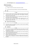
Function comparison table
the
last10
parameter
display mode
Keyboard and terminal UP /
DN function
PID Process
Injection molding machine
H0 function
X1X2 delay action
V5-H
V5-I-I0
Standard
Injection molding machine
Products
energy saving
√
×
√
×
√
×
×
√
×
√
V5-I Injection Molding Machine Energy-saving Inverter
V5-I injection molding machine for inverter User's manual
5
V&T Technologies Co., Ltd.
http://www.ecodrivecn.com
■The energy saving principle of variable frequency for injection molding
machine
On the injection molding machine, the pump motor power consumption accounted
for a high proportion of the whole power consumption, the frequency energy of the
injection molding machine for injection molding machine pump motor power-saving
control. Injection molding machines are changing the required pressure and flow in
the mold, mold shrinkage, injection, packing, cooling stage, all stages of electrical
engineering frequency operation, the output power is always the same; only by the
pump overflow flow valve to adjust the load pressure and flow, so that the utilization
efficiency of the pump motor is low, resulting in energy waste.
V5-inverter-based high-performance vector control technology to take the pressure
of injection molding machines and traffic signals as the control basis, to ensure that
the injection of different stages of flow and pressure at the same time, and adjust the
operating speed of the motor, the motor output power control in the optimal level, in
order to achieve the purpose of energy saving.
■ Technical characteristics of V5-I inverter
◆ Easy to install, no need to change the control mode of the original equipment, oil
and circuit structure.
◆ Inverter energy-saving standard configuration injection molding machine interface
card, independent of flow and pressure signals input signal specifications: 0 ~ 24V /
0 to 2A.
◆ Resistance to the current impact, excellent vector control features to ensure a
steady trip run, 200% overload 0.5 seconds.
◆ Super low speed with load capacity and fast speed control, 0.5Hz 180% starting
torque, the motor is accelerated to the fastest rated speed of 0.1 seconds.
◆ The output of high power factor, reactive power loss decreases when the
soft-start high-current shock.
◆ Supporting electric injection molding machine control performance is still superior
speed sensorless vector control mode, the output torque and accurate positioning.
6
V5-I injection molding machine for inverter User's manual
V&T Technologies Co., Ltd.
http://www.ecodrivecn.com
◆ Provides customized technology curve, when replacing the mold, the user need
to change the drive parameters, and easily the memory of the technology curve.
◆ A wide range of torque output, pressure and flow settings within the motor torque
output stability, to ensure the quality of the workpiece.
◆ The use of advanced power modules drive, eliminating the inverter operation
when the interference of the injection molding machine control circuits and sensors.
◆
V5-I Special function setting of inverter for injection molding machines
Function
number
H0.00
Name
The application if Injection molding machine
The injection
From the different definitions of the control parameter
machine frequency
set and stored in the inverter, through the control panel
given choice
The injection
H0.03
machine the
frequency for a
given user defined
Digital terminal
H1.00
logic operation
mode
or the terminal is available online and flexible switch
Flow and pressure curves (4 point 5 sections) each for
3, flow rate and pressure corresponding to the
frequency can be customized
Injection molding machine computer board on any
digital input of the inverter can be combined with "soft
PLC" logical operations and through inverter digital
terminal output result of the operation
Injection molding machine computer board on any
H1.08
Analog math
analog input of the inverter can be combined with "soft
mode
PLC" math and can control the output of the inverter
operation results
User-defined
A0.00
function code
explicit-implicit
password
the user can define your own code to hide the function
of converter and use password to protect code hidden
features
■ Flow and pressure signals to control the frequency setting
V5-I injection molding machine for inverter User's manual
7
V&T Technologies Co., Ltd.
http://www.ecodrivecn.com
■ programmable logic and math output
V5-I converter can provide a "soft PLC" programming function digital input terminal
of the inverter status and analog inputs, similar to the PLC software programming, by
the amount of the IO status “
Math, or, non-"logical operators or the analog input AI"
add, subtract, multiply, with the exception of "the result of the operation, and the
results sent to the inverter terminal output of a digital or analog terminal output, In
addition, the analog math results can also control the frequency output of the
inverter.
■ About logic operations
◆ The logic operation of the digital input state up to 11
◆ Can produce up to three separate logical result of the operation by the output of
the inverter Y1, Y2, relay terminal
◆ Each logic operation results up to the logical operations of the three digital input
status
◆ Each digital input status, or can be carried out, or, non-operating
◆ Can define the priority of logical operations between three digital input status
■ About math operation
◆ Involved in math analog input up to 5, voltage, current, pulse signal can be.
V5-I injection molding machine for inverter User's manual
8
V&T Technologies Co., Ltd.
http://www.ecodrivecn.com
◆ Math through the inverter AO1, AO2 terminal output
◆
Math results up to 3 analog input math
◆
Each analog input can be carried out between the "add, subtract, multiply, with
the exception of" Operation
◆
Can define the priority level of 3 between the analog input math
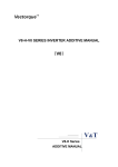
■
The use of the injection machine interface card
◆
Model
EX-PM01
◆
Technical indicators
Provides 2-way 24V input terminals.
2-way 0 ~ 2A, 0 ~ 1A Input terminal.
To determine the voltage / current input by jumper, jumper selectable current
input range of 0 ~ 2A, 0 ~ 1A.
◆ Interface card terminals appearance
The AV4/AI4 terminal input voltage or current flow signal, the input voltage
traffic signal, AV4 terminals AI4 terminal input current flow rate signal; AV5/AI5
terminal input voltage or current pressure signal, the pressure signal of the AV5
terminal input voltage, the AI5 terminal input current pressure signal.
◆ Interface card appearance
◆ Installation Diagram
V5-I injection molding machine for inverter User's manual
9
V&T Technologies Co., Ltd.
http://www.ecodrivecn.com
Function comparison table
V5-H V5-H
V5-I-I0 V5-I-I0 is
Standard
Injection molding
Products
machine energy saving
AV4/AI4, AV5/AI5 input
×
√
Digital input terminal delay
×
√
√
√
√
√
√
×
√
×
Simulated curves 2, 3 and 4 effective
User
terminal
485
and
the
master-slave mode
Auxiliary
to
the
set
as
well
as
computing
the last10 parameter display mode
Keyboard and terminal UP/DN function
√
×
Contents
V5-I injection molding machine for inverter User's manual
10
V&T Technologies Co., Ltd.
http://www.ecodrivecn.com
Chapter1 Function parameter list of the injection molding machine industry………9
1.1 Special Function parameter list of the injection molding machine industry…….9
1.2 The parameter setting and function list of input and output terminal…………12
Chapter2 The detailed explanation for the parameter function of injection molding
machine industry………………………………………………………………………….15
2.1 Energy-saving function parameters of the injection molding machine (H0
group) ……………………………………………………………………………………..15
2.2 Energy-saving function parameters
of the injection molding machine (H1
group) ……………………………………………………………………… ……………18
2.3 The input and output terminal function of the injection molding machine (P5
Group
P7
group) .......................... ................................ ........................... .......... ...................23
Chapter I
Function parameters list of the injection machine
industry
The indication and description of the function code parameter table
V5-I injection molding machine for inverter User's manual
11
V&T Technologies Co., Ltd.
http://www.ecodrivecn.com
Summary table
Explanation
Function code
H0.00 The code name of the function code, such as H0.00
Function code
The name of the function code, explaining the role of the functional
name
code
Factory setting
Setting range
Settings after the operation of the function code to restore factory
settings (see V5-H user manual the P0.01 instructions)
The function code allows a set of minimum to maximum
V: voltage; A: current;
℃: degree;
Ω: Ohm; mH: millihenry; rpm:
speed; %: Percentage; bps: the baud rate; Hz 、kHz: Frequency;
Unit
ms 、s 、min 、h 、kh : time kW: Power; m: m; km: one thousand
meters; /: Units
O: The function code running can be modified; ×: The function code
Property
can only be modified when in shutdown; *: The function code for
read-only parameter, can not be modified
Function code
option
Use setting
Function code parameter settings list
For the user to record parameters
1.1 Special function parameters for injection machine industry
V5-I injection molding machine for inverter User's manual
12
V&T Technologies Co., Ltd.
http://www.ecodrivecn.com
V5-I injection molding machine for inverter User's manual
13
V&T Technologies Co., Ltd.
http://www.ecodrivecn.com
Function
code
Function code name
Factory
setting
Setting
range
H0.09
the frequency curve 1 of
the injection machine is
input point A0
0
0.0~100.0
0.0-100.0
%
○
0.0%~100.0%
H0.10
the frequency curve 1 of
the injection machine is
input point A0. its
Reference value is B0.
0
0.0~100.0
%
○○
0.0%~100.0%
H0.11
the frequency curve 1 of
the injection machine is
input point A1
25
0.0~100.0
%
○
0.0%~100.0%
H0.12
the frequency curve 1 of
the injection machine is
input point A1. its
Reference value is B1
25
0.0~100.0
%
○
0.0%~100.0%
H0.13
the frequency curve 1 of
the injection machine is
input point A2
50
0.0~100.0
%
○
0.0%~100.0%
H0.14
the frequency curve 1 of
the injection machine is
input point A2. its
Reference value is B2
50
0.0~100.0
%
○
0.0%~100.0%
H0.15
the frequency curve 1 of
the injection machine is
input point A3
100
0.0~100.0
%
○
0.0%~100.0%
H0.16
the frequency curve 1 of
the injection machine is
input point A3. its
Reference value is B3
100
0.0~100.0
%
○
0.0%~100.0%
H0.17
the frequency curve 2 of
the injection machine is
input point A0
0
0.0~100.0
%
○
0.0%~100.0%
H0.18
the frequency curve 2 of
the injection machine is
input point A0. its
Reference value is B0
0
0.0~100.0
%
○
0.0%~100.0%
Unit Property
Function
code option
V5-I injection molding machine for inverter User's manual
14
V&T Technologies Co., Ltd.
http://www.ecodrivecn.com
Function
code
Function code name
Factory
setting
Setting
range
Unit
Property
Function
code option
H0.19
the frequency curve 2 of
the injection machine is
input point A1
25
0.0~100.0
%
○
0.0%~100.0%
H0.20
the frequency curve 2 of
the injection machine is
input point A1. its
Reference value is B1
25
0.0~100.0
%
○
0.0%~100.0%
H0.21
the frequency curve 2 of
the injection machine is
input point A2
50
0.0~100.0
%
○
0.0%~100.0%
50
0.0~100.0
%
○
0.0%~100.0%
100
0.0~100.0
%
○
0.0%~100.0%
100
0.0~100.0
%
○
0.0%~100.0%
0
0.0~100.0
%
○
0.0%~100.0%
0
0.0~100.0
%
○
0.0%~100.0%
25
0.0~100.0
%
○
0.0%~100.0%
H0.22
H0.23
H0.24
the frequency curve 2 of
the injection machine is
input point A2. its
Reference value is B2
the frequency curve 2 of
the injection machine is
input point A3
the frequency curve 2 of
the injection machine is
input point A3. its
Reference value is B3
the frequency curve 3 of
H0.25
the injection machine is
input point A0
the frequency curve3 of the
H0.26
injection machine is input
point A0. its Reference
value is B0
the frequency curve 3
H0.27
of
the injection machine is
input point A1
V5-I injection molding machine for inverter User's manual
15
V&T Technologies Co., Ltd.
http://www.ecodrivecn.com
Function
code
Function code name
Factory
setting
Setting
range
H0.28
the frequency curve3 of the
injection machine is input
point A1. its Reference
value is B1
25
0.0~100.0
%
○○
0.0%~100.0%
H0.29
the frequency curve 3 of
the injection machine is
input point A2
50
0.0~100.0
%
○○
0.0%~100.0%
H0.30
the frequency curve3 of the
injection machine is input
point A2. its Reference
value is B2
50
0.0~100.0
%
○
0.0%~100.0%
H0.31
the frequency curve 3 of
the injection machine is
input point A3
100
0.0~100.0
%
○
0.0%~100.0%
100
0.0~100.0
%
○
0.0%~100.0%
○
Retention
H0.32
H0.33
the frequency curve3 of the
injection machine is input
point A3. its Reference
value is B3
Manufacturer-specific
functions 11 (reserved)
0
0~6553 /
Function
code option
Unit Property
H0.34.
Manufacturer-specific
functions 12 (reserved)
0
0~65535
/
○
Retention
H0.35
Manufacturer-specific
functions 13 (reserved)
00
0~65535
/
○
Retention
Digital output
terminal logic
operation, the
operation result
H1.00
Digital terminal logic
operation mode
0
0~111
/
○
in H1.07 bit: an
digital output;
Ten: two digital
outputs; One
hundred: 3
digital outputs;
Function
Function
Factory
Setting
Unit
Property
Function
V5-I injection molding machine for inverter User's manual
16
V&T Technologies Co., Ltd.
code
H1.00
code
name
Digital
terminal
logic
operation
mode
http://www.ecodrivecn.com
setting
range
0
0~111
code option
/
○
H1.01
Y1
terminal
logic
operation
port
settings
1
1~AA
A
/
○○
H1.02
Y1
terminals
logical
relationsh
ip
settings
0
0~111
7
/
○
1000-bit: reservations; 0:
Disabled; 1: Effective
Bits:
a
digital
input
terminal
1~ A: X1 ~ X7, AI1 ~ AI3
(for digital terminals);
10-bit digital input
terminals 2: 0: digital
input terminal without a
valid choice; 1~ A: X1 ~
X7, AI1 ~ AI3 (for digital
terminals); one hundred
digital input terminals: The
digital input terminal
without a valid choice; 1 ~
A,: the X1 ~ X7, AI1 ~ AI3
(for digital terminals);
1000: Reserved
Bits: the digital input
terminal "non-operating
0 ~ 7: 3-8 decoding of the
digital terminal,
1: corresponds to the
non-operators;
10: in front of a digital
input terminal or operation
0:; 1: or; One hundred: two
digital input terminals "or"
Operation: 1: or; 1000:
operator priority setting
0: digital input terminals
1, 2 op-priority high;
1: digital input terminals 2,
3 op-priority high;
V5-I injection molding machine for inverter User's manual
17
V&T Technologies Co., Ltd.
http://www.ecodrivecn.com
Function
code
Function
code name
Factory
setting
Setting
range
Unit
Property
Function
code option
H1.03
terminal logic
operation port
settings
0
0~AAA
/
○
Same as H1.01
H1.04
Y2 terminals
logical
relationship
settings
1
1~1117
/
○
Same as H1.02
H1.05
Relay terminal
logic operation
port settings
0
0~AAA
/
○
Same as H1.01
H1.06
Logical
relationship
between setting
of the relay
terminal
1
1~1117
/
○
Same as H1.02
H1.07
Digital terminal
logic operation
output
Show
0
0~FFFF
/
*
H1.08
Analog math
mode
0
0~1
/
○
State of the digital
input terminal
logic operation
results: Bits: a
digital output;
Ten: two digital
outputs; One
hundred: 3 digital
outputs; 1000-bit:
reservations;
Analog input
terminal
arithmetic
operations, the
operation results
in H1.110: Invalid;
1: Effective
V5-I injection molding machine for inverter User's manual
18
V&T Technologies Co., Ltd.
Function
code
H1.09
H1.10
Function
code
name
Analog
Terminal
math
Port
Set
Analog
Terminal
math
relations
Factory
setting
http://www.ecodrivecn.com
Setting
range
Unit
Property
4
1~555
/
○
0
0~122
7
/
○
Function
code option
Bits: an analog input
terminal
1 ~ 5 : AI1~AI3 ,
AV4/AI4 , AV5/AI5 ;
ten: two analog input
terminal
0: Analog input
terminals without a
valid
1 ~ 5: AI1 ~ AI3,
AV4/AI4, AV5/AI5;
one hundred: 3
analog input terminal
0: Analog input
terminals without a
valid c 1 ~ 5: AI1 ~
AI3, AV4/AI4,
AV5/AI5; one
thousand: Reserved
Bits: analog input
"negated" operation
0 ~ 7: 3-8 decoding of
the digital terminal, 1:
corresponds to the
non-operators; 10: 1
before computing the
analog input
operation 0: "+"; 1:
"x";: "/" ;
One hundred: two
analog input
"operator" operation:
"+";: "x";: "/";
1000: operator
priority setting 0:
Analog input 1, 2
op-priority high; 1:
Analog input 2, 3 op
high priority;
V5-I injection molding machine for inverter User's manual
19
V&T Technologies Co., Ltd.
http://www.ecodrivecn.com
Function
code
Function
code name
H1.11
Analog
Terminal math
output
AIM Display
AIM
0.0
0.0~6553.5
%
*
H1.12
Analog
Terminal math
output
Function is set
0
0~1
/
○
0
0~65535
/
○
0~65535
0
0~65535
/
○
0~65535
0
0~65535
/
○
0~65535
0.0
0.0~6553.5
%
*
0~65535
0.0
0.0~6553.5
%
*
0~65535
0.0
0.0~6553.5
%
*
0~65535
0.0
0.0~6553.5
%
*
0~65535
H1.13
H1.14
H1.15
d2.18
d2.19
d2.20
d2.21
Industry
functionality
H113 in group
H1
H1 group of
industries,
functions H114
H1 group of
industries,
functions H115
AV4/AI4 enter
one
hundred
components
AV4/AI4 after
transformation
by the curve of
one
hundred
components
AV5/AI5 enter
one
hundred
components
AV5/AI5 after
transformation
by the curve of
one
hundred
components
Factory
setting
Setting
range
Unit
Property
Function
code option
0 ~ 100%
Arithmetic
operations of
analog input
terminals: 0 to
100%
The analog
input terminal
arithmetic
operation
result the role
of 0: no
effect; 1: The
frequency or
speed
settings;
1.2 Patameters list for input and output erminal function set
V5-I injection molding machine for inverter User's manual
20
V&T Technologies Co., Ltd.
http://www.ecodrivecn.com
Table 1-1 Multi-function input terminal definition table
V5-I injection molding machine for inverter User's manual
21
V&T Technologies Co., Ltd.
Serial
number
http://www.ecodrivecn.com
Function defined
Serial
number
Function defined
0
Inching Forward
1
Point dynamic inversion
2
Forward (FWD)
3
Reverse (REV)
4
Three-wire operation control
5
Pulse frequency DI input
(only X7/DI terminal)
6
The digital voltage terminal
1
7
The digital voltage terminal 2
8
The digital voltage terminal
3
9
Multi frequency Terminal 1
10
Multi-frequency terminals 2
11
Multi frequency Terminal 3
12
Multi frequency Terminal 4
13
1 Acceleration and
deceleration time of terminal
1
14
Acceleration and
deceleration time of terminal
2
15
Digital adjust the frequency
clear
16
Frequency increment
instruction
17
Frequency decrement
instruction
18
Acceleration and
deceleration prohibit
instruction
19
External fault input
20
Terminal fault reset input
21
External interrupt contact
input
22
Inverter operation prohibits
23
Terminal shutdown
24
Terminal free Parking
25
1 Terminal DC brake 1
26
Emergency stop (the fastest
stop)
27
Terminal DC braking 2
28
Counter trigger input
29
Counter trigger cleared
30
Retention
31
Retention
V5-I injection molding machine for inverter User's manual
22
V&T Technologies Co., Ltd.
http://www.ecodrivecn.com
32
Flow for a given force the
Select curve 1
33
Flow for a given force select
the curve
34
Flow for a given force select
the curve
35
Pressure for a given force
select the curve
36
Pressure for a given force
select the curve
37
Pressure for a given forced to
choose curve 3
38
40
Forced to switch to the the
injection machine frequency
for a given user-defined way
Forced to switch to the the
injection machine frequency
for a given user-defined way
39
41~46 4
47
Forced to switch to the the
injection machine frequency
for a given user-defined way
Retention
PG pulse closed-loop
feedback single-phase input
48
Command cut to the
operation panel
50
Command cut the first bit
machine
51
52
The main frequency source
switch to digital
53
54
The main frequency source
is cut to AI1
55
The main frequency source to
cut to the AI2
56
The main frequency source
cut to AI3
57
The main frequency source to
cut to the DI
58
The auxiliary frequency
source to cut to the invalid
59
Retention
60
Auxiliary frequency source
cut to AI1
61 61
Auxiliary frequency source to
cut to the AI2
62
Auxiliary frequency source
cut to AI3
63 63
Auxiliary frequency source to
cut to the DI
64
Control the speed / torque
control switch
65 ~ 98
49
Command cut to the terminal
Main
frequency
source
closed-loop and open-loop
switching input
Retention
Retention
Compared with the V5-H, new features 32-40.
V5-I injection molding machine for inverter User's manual
23
V&T Technologies Co., Ltd.
http://www.ecodrivecn.com
Table 1-2 multi-function switch output function definition table
Feature
Meaning
set
0
2
4
Inverter operation signal (RUN)
Frequency level detection
signal 1 (FDT1)
Inverter or motor overload
pre-alarm detection signal (OL)
Feature
1
3
5
6
External downtime (EXT)
8
Lower limit of frequency (FLL)
99
10
Preset count value action
11
12
Retention
13
14
Drive fault
15
16
Retention
17
18
Setting the continuous
operation time to reach
20
Output X2
22
Zero current is detected (as
opposed to motor)
24~31
32
7
19
21
23
Frequency arrival signal
(FAR)
Frequency level detection
signal 2 (FDT2)
Undervoltage lockout stop
(LU)
The upper frequency limit
restrictions (FHL)
Inverter running at zero
speed
Reaches a count of action
Inverter operation ready to
complete (the RDY)
Inverter alarm
Set the total running time
to reach
Output X1
Retention
Stop command
instructions
Retention
A digital output of the logic
operation
34
Meaning
set
3 digital outputs of the logic
operation
33
35~47
Two digital output of the
logic operation
Retention
V5-I injection molding machine for inverter User's manual
24
V&T Technologies Co., Ltd.
http://www.ecodrivecn.com
Table 1-3 Multi-function analog output and pulse output functions definition
Feature
set
48
49
50
51
52
53
54
Output
signal
The definition of the analog
Pulse output range
output range
defined
selection
Output
The maximum frequency P0.11
frequency
corresponds to 10V/20mA
Set the
The maximum frequency P0.11
frequency
corresponds to 10V/20mA
Output
current
Motor
current
2 times the nominal
current corresponding to the
drive current
10V/20mA
corresponds to P7.10
Two times the motor rated
Two times the motor
current
rated current
corresponds
corresponds to P7.10
corresponds to 10V/20mA
voltage of P0.12 corresponds
in 10V/20mA
1000V
AI1
AI2
in
10V/20mA
10V/20mA;
Same as AI1
torque corresponds to
2 times the maximum
output voltage
corresponding to at
P7.10
corresponding
corresponding
2 times the rated motor
P7.10
2 times the maximum output
corresponding 5V/10mA
56
to
10V/20mA
10V
55
frequency P0.11
2 times the nominal drive
torque
Bus voltage
The maximum
corresponds to P7.10
2 times the rated motor torque
voltage
frequency P0.11
corresponds to P7.10
Output
Output
The maximum
1000V corresponds to
at P7.10
in
of
20mA
10V corresponds to
20mA corresponds to
50% of the P7.10 to
P7.10;
Same as AI1
V5-I injection molding machine for inverter User's manual
25
V&T Technologies Co., Ltd.
57
58
59
AI3
Maximum input pulse
Maximum input pulse
frequency P5.10 corresponds
frequency P5.10
to 10V/20mA
corresponds to P7.10
2 times the motor rated output
2 times the rated motor
power corresponding in
output power
10V/20mA
corresponds to P7.10
10000 corresponds to at
10000 corresponds to at
10V/20mA
P7.10
Curve correction reference
Curve correction
value 100% corresponding to
reference value 100%
10V/20mA
corresponding to P7.10
AV5/AI5
Same as AV4/AI4
Same as AV4/AI4
AIM
The reference value through
The reference value
H1.11 100% corresponding to
through H1.11 100%
10V/20mA
corresponding to P7.10
DI
Output
power
of the host
Retention
AV4/AI4
64
65
66
-10V ~ 10V corresponds
to the 0 ~ P7.10
computer
61~63
-10V ~ 10V corresponds to 0
~ 10V/20mA
Percentage
60
http://www.ecodrivecn.com
V5-I injection molding machine for inverter User's manual
26
V&T Technologies Co., Ltd.
http://www.ecodrivecn.com
Chapter 2 detailed function parameters in Injection molding
machine industry
2.1 Injection machine energy-saving function parameters (H0
group)
H0.00
Injection molding machine frequency given
0-3
method choice
Make sure the given method of inverter frequency in the energy-saving mode of the
injection machine. Depend on the different use environment or mold can set different
user injection machine frequency given user-defined mode.
0: do not use the the injection machine frequency for a given user-defined;
If the flow and pressure signal of injection machine for 0 ~ 10V or 0 to 20mA
available to input of the inverter terminals, there is no need to use injection machine
interface card; P6 group frequency curve can be achieved by controlling the terminal
AI input and the frequency of the inverter given.
1: Use the the injection machine frequency for given user defined method 1;
If you use Injection machine interface card to change the flow and pressure
signals sent to the inverter, the flow and pressure signals in accordance with the the
H0.03 Injection machine frequency of a given user-defined to determine the
frequency of the inverter is given.
2: Use Injection machine frequency for given user-defined method 2;
If you use injection machine interface card to change the flow and pressure
signals and sent it to the inverter, the flow and pressure signals in accordance with
the the H0.05 Injection machine frequency for given user-defined method 2 to
determine the frequency given of frequency inverter.
3: use injection machine frequency for given user-defined method 3;
If you use Injection machine interface card to change the flow and pressure
signals and sent it to frequency inverter, the flow and pressure signals in accordance
with H0.07 Injection machine frequency for given user-defined method 3 to
V5-I injection molding machine for inverter User's manual
27
V&T Technologies Co., Ltd.
http://www.ecodrivecn.com
determine the frequency given of frequency inverter.
Note: to select different injection machine frequencies for a given user-defined way
through the switching of
terminal.
H0.01
Flow signal AV4/AI4 filter time
0.000 ~ 1.000s
H0.02
Pressure signal AV5/AI5 filter time
0.000 ~ 1.000s
Can be realized digital filtering of the flow and pressure signals through the above
function code , in order to improve anti-jamming capability; but large filter time
response speed will cause the system to perform slower.
H0.03
Injection machine the frequency given
0 ~ 1222
user-defined way 1
User-defined the injection machine frequency given method 1.
The operator panel display
Flow pressure input selection
Bits
0: the flow and pressure signals are valid; 1: the only traffic signal
is valid;
2: Only the pressure signal;
Flow for a given curve to select
tens
0: the Injection machine frequency curve 1;
1:Injection machine
frequency curve;
2: the Injection machine frequency curve;
Pressure for a given curve to select
hundreds
0: the Injection machine frequency curve 1;
1:Injection machine
frequency curve;
2: the injection machine frequency curve;
kilobit
The relationship between flow and pressure selection
0: K1, * flow + (1-K1) pressure; 1: Max {flow, pressure};
Function code to determine the flow and pressure signals can be determined as the
frequency given. When only choice one of signals between the flow signal and
28
V5-I injection molding machine for inverter User's manual
V&T Technologies Co., Ltd.
http://www.ecodrivecn.com
pressure signals as the frequency given
another signal on the frequency given is
no effect.
0: the flow and pressure signals are valid;
1: only the traffic signal;
2: Only the pressure signal;
10-bit function code determine the amendments to the traffic signal frequency curve.
Frequency curve of the external input flow signal into the analog machine, the signal
input through the conversion in accordance with the 0 to the maximum input
corresponds to the 0 to 100% per unit amount of converted; per unit volume and the
maximum output frequency of P0.11 The product of the traffic signal corresponding
to the set frequency component.
0: the Injection machine frequency curve;
1: the Injection machine frequency curve;
2: the injection machine frequency curve;
hundreds of the function code determine the frequency curve of the correction
pressure signal. Frequency curve to the pressure of external input signal into the
analog machine, the signal input through the conversion in accordance with the 0 to
the maximum input corresponds to the 0 to 100% per unit amount of converted; per
unit volume and the maximum output frequency ofP0.11 The product of the pressure
signal corresponding to the set frequency component.
0: the Injection machine frequency curve;
1: the Injection machine frequency curve;
2: the Injection machine frequency curve;
kilobit of the function code to determine the flow and pressure signals at the same
time as the frequency to the timing, Flow signal and pressure signal corresponding
to the frequency component of the manner in which the synthesis of the final set
frequency output. If you select only the flow and pressure signals in a signal as the
frequency of a given time, this bit is set is not valid.
0: Synthesis for weight, weight K1 is set by the H0.04;
Final set frequency output = K1 × flow frequency components + (1-K1) ×
pressure frequency components;
V5-I injection molding machine for inverter User's manual
29
V&T Technologies Co., Ltd.
http://www.ecodrivecn.com
1: check the flow and pressure signals corresponding to the maximum frequency
component;
The final set frequency output = Max {flow, pressure};
H0.04
Flow coefficient K1
0.0-100.0
Make sure the user-defined Injection machine frequency given the flow and pressure
signals at the same time as the frequency to the timing frequency component of the
right weight.
H0.05
Injection machine the frequency for a given
0 ~ 1222
user-defined mode
H0.06
Flow coefficient K2
0.0~ 100.0
H0.07
Injection machine the frequency for a given
0 ~ 1222
user-defined mode
H0.08
Flow coefficient K3
0.0~ 100.0
Determine the user-defined the injection machine frequency given way 2 and 3, the
same meaning as above.
H0.09
injection molding machine the frequency curve of 1
input point A0
0.0-100.0
V5-I injection molding machine for inverter User's manual
30
V&T Technologies Co., Ltd.
H0.10
H0.11
http://www.ecodrivecn.com
Injection molding machine the frequency curve of 1
input point A0 per unit volume corresponding to B0
Injection molding machine the frequency curve of 1
input A1
0.0-100.0
0.0-100.0
Injection molding machine the frequency curve of 1
H0.12
input point A1 per unit volume corresponding to the
0.0-100.0
B1
H0.13
Injection molding machine the frequency curve of 1
input A2
0.0-100.0
Injection molding machine the frequency curve of 1
H0.14
input point A2 corresponding to the per unit amount of
0.0-100.0
B2
H0.15
Injection molding machine the frequency curve of 1
input point A3
0.0-100.0
Injection molding machine the frequency curve of 1
H0.16
input point A3 corresponding to the amount of per unit
0.0-100.0
B3
Above function code can be set to the frequency curve of the first group. Frequency
curve of the external input signal into the analog machine, input signal after
conversion in accordance with the 0 to the maximum input corresponding to 0~100%
per unit amount of converted; per unit volume and the product of the maximum
output frequency of P0.11 determine the component of the signal corresponding to
the set frequency.
H0.17
Injection machine the frequency curve of the input point
0.0-100.0
A0
V5-I injection molding machine for inverter User's manual
31
V&T Technologies Co., Ltd.
H0.18
http://www.ecodrivecn.com
Injection machine frequency curve input per unit volume
0.0-100.0
B0 A0 corresponds
H0.19
The Injection machine frequency curve 2 input A1
0.0-100.0
H0.20
Injection machine frequency curve input points A1
0.0-100.0
corresponding per unit volume B1
H0.21
Injection machine the frequency curve 2 input point A2
0.0-100.0
H0.22
Injection machine frequency curve of the input point A2
0.0-100.0
corresponding to the amount of per unit B2
H0.23
The Injection machine frequency curve input A3
0.0-100.0
H0.24
Injection machine the frequency curve of two input points
0.0-100.0
A3 per unit volume corresponding to the B3
The above function code can be set to the second group of frequency curve, the
same way as the first set of frequency curves.
H0.25
H0.26
H0.27
H0.28
H0.29
H0.30
H0.31
H0.32
Injection molding machine frequency curve 3 input point
A0
Injection molding machine frequency curve input per unit
volume B0 A0 corresponds
Injection molding machine the frequency curve 3 input
point of A1
Injection molding machine frequency curve input points
A1 corresponding per unit volume B1
the injection machine frequency curve 3 input A2
Injection molding machine the frequency curve per unit
volume of three input A2 corresponding B2
the injection machine frequency curve input A3
Injection molding machine the frequency curve input A3
per unit volume corresponding to the B3
0.0 ~100.0
0.0-100.0
0.0-100.0
0.0-100.0
0.0-100.0
0.0-100.0
0.0-100.0
0.0-100.0
Above function code can be set to the third group of the frequency curve, the same
way as the first set of frequency curves.
V5-I injection molding machine for inverter User's manual
32
V&T Technologies Co., Ltd.
http://www.ecodrivecn.com
H0.33
Manufacturer-specific functions 11 (reserved)
0 - 65535
H0.34
Manufacturer-specific functions 12 (reserved)
0 - 65535
H0.35
Manufacturer-specific functions 13 (reserved)
0 - 65535
The above function code reserved.
2.2 Injection machine energy-saving function parameters (H1
group)
H1.00
Digital terminal logic operation mode
0 to 111
Can achieve three digital input terminal signal after "AND, or NON-" the digital output
and non-logical operations, so that the digital output of up to 3. The logical result of
the operation of the three digital terminal in H1.07, If select the digital output is
invalid, the logical result of the operation of the digital terminal is always 0. Digital
terminals logical result of the operation through a programmable digital output port
Y1, Y2 or relay output.
The operator panel display
A digital input
Bits
0: Disabled; 1: Effective
2 digital inputs
tens
0: Disabled; 1: Effective
hundreds
kilobit
H1.0 1
3 digital inputs
0: Disabled; 1: Effective
Retained;
Digital terminal a logical operator port settings
1 ~ AAA-
Determine the three digital input terminal signal involved in the logical operators to
determine a digital output port, after the logic operation.
V5-I injection molding machine for inverter User's manual
33
V&T Technologies Co., Ltd.
http://www.ecodrivecn.com
The operator panel display
1 digital output
Bits
1 ~ A,: the X1 ~ X7, AI1 ~ AI3 (for digital terminals);
2 digital outputs
tens
1 ~ A,: the X1 ~ X7, AI1 ~ AI3 (for digital terminals);
3 digital outputs
hundreds
1 ~ A,: the X1 ~ X7, AI1 ~ AI3 (for digital terminals);
kilobit
H1.0 2
Retained;
A logical relationship of the digital terminal settings
0 ~ 1117
Determine the logical operations between three digital input, determined after the
logic operation of a digital output.
The operator panel display
"Operation of the digital input terminal "NON-" (0 to 7
Bits
corresponding Bit0 ~ 2)
Bit0 ~ 2 corresponding to digital input 1
to 3; 1 means non-operating;
The first
tens
digital input terminal "AND / OR "operator <OP1>
0: AND; 1: OR;
The second digital input terminals "AND / OR " operating <OP2>
hundreds
0: AND; 1: OR;
Computing the priority level set
kilobit
0: digital input terminals 1, 2 Operation high priority;
1: digital input terminals 2, 3 Operation high priority;
A bit determines whether digital input firstly go through the "non-action"; the setting 0
to 7 the corresponding binary Bit0 ~ 2
Digital terminal operator <NON> (the H1.02 a bit determines)
Digital
input
0
1
2
3
4
5
6
V5-I injection molding machine for inverter User's manual
7
34
V&T Technologies Co., Ltd.
http://www.ecodrivecn.com
terminal
Terminal 1
<NON1>
Terminal 2
<NON2>
Terminal 3
<NON3>
tens
and
/
Non-
/
Non-
/
Non-
/
Non-
/
/
Non-
Non-
/
/
Non-
Non-
/
/
/
/
Non-
Non-
Non-
Non-
hundreds
determine
the
operator
among
the
digital
input
terminals<OP1> and <OP2>;"and" operation is expressed as the <AND>, "or"
operation is expressed as <OR>.
kilobit determine the sequence of logical operations between the digital input
terminals;
0: digital input terminals 1, 2 Operation high priority;
1: digital input terminals 2, 3 Operation high priority;
For example: Select X1, X2, X3, as three digital input terminals, respectively
corresponding to the digital input terminals 1 ~ 3, after logic operations the results
showed In the first digital output ; to achieve the following logical operations: the
first digital output = (X3 <AND> (<NON> X2)) <OR> X1; other digital output is not
valid.
Determine digital terminals1 logical operator port : H1.01 = 0321.
Make sure the setting mode of digital terminal logic operation: H1.00 = 0001.
Determine the "non-operation: X3 and X1 no" NON-"operation, X2 has a "
NON-"operation; so <NON3> = <NON1> =" / "; <NON2> =" non ", based on table
digital terminal 1 logic relationship set of 2;
Determine the first digital input terminal "AND,OR" Operation: <OP1> = <OR>,
tens of a logical relationship of the digital terminal is set to 1;
Determine the second digital input terminals "AND,OR" operation: set by <OP2>
= the <AND> Hundred of a logical relationship of the digital terminal is set to 0;
Determine the operator priority: the digital input terminals 2, 3 computing priority,
kilobit of a logical relationship of the digital terminal is set to 1;
Ultimately determine digital terminal 1 logical relationship is setting H1.02 = 1012.
V5-I injection molding machine for inverter User's manual
35
V&T Technologies Co., Ltd.
http://www.ecodrivecn.com
The result of logic operation of the digital terminal for the first digital output, shown by
H1.07 of bits, and through a programmable digital output port of Y1, Y2 or relay
output.
H1.03
Digital terminal 2 logic operation port setting
0 ~ AAA
H1.04
Digital terminal 2 logical relationship setting
1 ~ 1117
H1.0 5
Digital terminal 3 logic operation port setting
0 ~ AAA
H1.0 6
Digital terminal 3 logical relationship setting
1 ~ 1117
Determine with logic operation, the three digital input terminal signal port and
determine the relationship between three digital input logic operations, after the logic
operation to determine the second and the third digital outputs.
H1.0 7
Digital terminal logic operation output
0 ~ FFFF
Showed 3 digital terminals logical result of the operation, if the defined digital output
is invalid, the logical
operation result of the digital terminal is always 0.
The operator panel display
Bits
A digital output: 0 to 1;
tens
2 digital outputs: 0 to 1;
hundreds
3 digital outputs: 0 to 1;
kilobit
Reservation
H1.0 8
Analog math mode
0 to 1
Three analog inputs can be realized though "Math" of math operation to produce
results, the results displayed in the analog terminals math output H1.11, if you
choose analog math mode is invalid, the results of the analog input math to 0. The
result of the operation can be used to make the inverter frequency setting AO
terminal or through a programmable output.
0: invalid;
1: effective;
V5-I injection molding machine for inverter User's manual
36
V&T Technologies Co., Ltd.
H1.09
http://www.ecodrivecn.com
Math port settings of the analog terminals
1 ~ 555
Determine the logic operation three analog input signal port
The operator panel display
The First analog input terminal 1-5: AI1 ~ AI3, AV4/AI4,
Bits
AV5/AI5;
The second analog input terminal
tens
0: Analog input terminals 5
and 1: AI1 ~ AI3, AV4/AI4, AV5/AI5;
The third analog input terminal
hundreds
0: Analog input terminals is invalid
1-5: AI1 ~ AI3, AV4/AI4, AV5/AI5;
kilobit
H1.10
Reservation
Analog terminal math relations set
0 ~ 1277
Determine 3 analog input math relations, after a number crunching to determine the
final output.
The operator panel display
Analog inputs inverted operation (0 to 7 corresponding to Bit0 ~ 2)
Bits
Bit0 ~ 2 corresponding to digital input 1 to 3; 1 indicates that the
inversion operation;
First An analog input "operator" operator
tens
0: "+"; 1: "×"; 2: " /'';
hundreds
kilobit
First Two analog input "operator" operator
0: "+"; 1: "×"; 2: " / ";
0: Analog input 1, 2 computing high priority;
1: Analog input 2, 3 operator priority;
Bits to determine whether the analog input go through the "inversion" operation, if
the original analog positive becomes to negative, the original analog negative
becomes to positive;
the setting of 0 ~ 7 to corresponding binary Bit0 ~ 2.
V5-I injection molding machine for inverter User's manual
37
V&T Technologies Co., Ltd.
http://www.ecodrivecn.com
tens and hundreds to determine the operator between the analog input <OP1>,
<OP2> .
kilobit determine the sequence of logical operations between the analog input;
0: Analog input 1, 2 computing high priority;
1: Analog input 2, 3 operator priority;
An example: Choose the analog input of AI1, AI2, AI3 corresponding to 3 analog
inputs, the results showed after math in H1.11 ; Achieve the following math: H1.11 =
(AI3 × (- AI2)) + AI1.
Math ports of analog terminals: H1.09 = 0321.
Determine analog Terminal math mode settings: H1.08 = 1.
Make sure "negated "Operation: AI3 and AI1 have no "negated operation, AI2 has
"negated" operation; So <NON3> = <NON1> = "/";
<NON2> = "Negated", According above Table bits of analog terminal math operation
relations is set to
2;
Determine before "Operator" operation of the first analog inputs: <OP1> = "+" 10-bit
of analog terminal math operation relations set to 0;
Determine before "Operator" operation of the second analog inputs: <OP2> = "x"
hundreds of analog terminal math operation relations set to 1;
Determine the operator priority: the analog input 2, 3 between the operator priority,
kilobit of analog terminal math operation relations set to1;
To finalize the analog terminals math relations settings H1.10 = 1102.
Analog terminal math results by The H1.11 show. The result of the operation can be
used to make the inverter frequency setting volume or by programmable AO
V5-I injection molding machine for inverter User's manual
38
V&T Technologies Co., Ltd.
http://www.ecodrivecn.com
Terminal output.
Note: The analog input in the machine are normalized 0 ~ 10V signal, such as AI1
current signal 0 ~ 20mA, AV4/AI4 current signal 0 ~ 1.0A,
AV5/AI5 voltage signal 0 ~ 24V are in the machine specification into a 0 ~ 10V
signal.
H1.11
Analog terminal math output display
0.0 ~ 6553.5
Show 3 analog input math results, has been defined to invalidate the results of
mathematical operations, analog terminal math results always is 0.
The results show that as a percentage of the amount of 0 ~100.0% corresponds to
0 ~ 10V math results.
H1.12
Math output function settings of the analog
0~1
terminals
Determine the analog terminal math output H1.11 is set as the frequency of the
inverter; 0 ~100.0% corresponds to 0 ~ maximum output frequency P0.11.
0: no effect.
1: Analog terminal math operation output H1.11 is set as the frequency of the
inverter.
H1.13
Industry functionality H113 in group H113
0 ~ 65535
H1.14
H1 group of industries, functions H114
0 ~ 65535
H1.15
H1 group of industries, functions H115
0 ~65535
Reservation
d2.18
d2.19
d2.20
d2.21
AV4/AI4 enter hundreds components
AV4/AI4 after transformation by the curve of
hundreds components
AV5/AI5 enter hundreds components
AV5/AI5 after transformation by the curve of
hundreds components
0 ~ 65535
0 ~ 65535
0 ~65535
0 ~ 65535
d2.18 and d2.20 is the maximum input hundred components about the AV4/AI4 and
AV5/AI5 input relative to the of AV4/AI4 and AV5/AI5 ;d2.19 and d2.21 is the Per unit
volume of the injection machine frequency curve correction of AV4/AI4, and
AV5/AI5 . d2 group are read-only parameter.
V5-I injection molding machine for inverter User's manual
39
V&T Technologies Co., Ltd.
http://www.ecodrivecn.com
2.3 Injection machine the input and output terminals function (P5
group ~ P7 group)
P0.01
Functional Protection
0 ~5
This function is used to set change permissions and initialization level of
parameters .
0: All parameters are allowed to change.
1: all parameters are prohibited changes.
2: all The parameters of the P region restore to the factory settings.
3: Except the motor group parameters (P9 group) The parameters of the P region
restore to the factory settings.
4: all The parameters of H restore to the factory settings.
5: reservation.
P5.00
X1 video input select function
0 ~99
P5.01
X2 video input selection
0 ~ 99
P5.02
X3 video input selection function
0 ~99
P5.03
X4 terminal input select
0 ~99
P5.04
X5 terminal input select
0 ~99
P5.06
The X6 video input selection
0 ~99
P5.07
X7 terminal input select
0 ~99
The following list only add and modify the menu item, not listed in the function V5-H
is consistenst. Please refer to V5-H user manual.
32
Flow for a given force to select
33
Flow for a given force to
V5-I injection molding machine for inverter User's manual
40
V&T Technologies Co., Ltd.
http://www.ecodrivecn.com
the curve 1
34
36
select the curve 2
Flow for a given force to select
the curve 3
Pressure for a given force to
select the curve 2
35
37
machine frequency for a given
to select the curve A
Pressure for a given force
to select the curve 3
Forced to switch to the
Forced to switch to the Injection
38
Pressure for a given force
39
user-defined way 1
Injection machine
frequency for a given
user-defined way 2
Forced to switch to the Injection
40
machine frequency for a given
41 to 46
user-defined way 3
32 to 34: flow given forced choice
Flow given AV4/AI4 forced through the function to select the injection machine
frequency curves 1 ~3, but if forced to select two or more traffic given injection
machine at the same time
The frequency curve of the terminal function is invalid, Flow given to maintain the
original way.
35-37: Pressure given forced choice
Pressure given AV5/AI5
forced through the function to select the injection machine
frequency curves 1 ~3, but if forced to select two or more traffic given injection
machine at the same time The frequency curve of the terminal function is invalid,
Voltage given to maintain the original way.
38 to 40:Injection machine forced to select the frequency of a given user defined
Select three kinds of injection machine frequency given a user-defined way through
the terminal. However, if forced to select more than two injection machine frequency
at the same time,
Given user defined function is not terminal. Injection machine the frequency of a
V5-I injection molding machine for inverter User's manual
41
V&T Technologies Co., Ltd.
http://www.ecodrivecn.com
given user defined to maintain the original way.
P7.00
Y1 terminal output selection function
0 to 47
P7.01
Y2/DO terminal output selection
0 to 71
P7.02
Continued electrical terminals output options
0 to 47
P7.03
The AO1 terminal output options
48 to 71
P7.05
AO2 terminal output selection function
48 to 71
Y1 and the relay terminals can be defined as a multi-function digital output; AO1
and AO2 terminal can be defined as a multi-function analog output, and Jumper
choose the type of analog output (0 ~ 10V / 0 ~ 20mA).
Y2 terminals can be used as a multi-function digital output is also available as
high-speed pulse output (0 ~ 50kHz).
Noted as Below are just new functions, consistenst with the V5-H general-purpose
inverters usage. Please refer to the V5-H general purpose inverter user manual.
Table Functions defined in Table 2-1 multi-function switch output
Featur
Meaning
e set
32
34
A digital output of the logic
operation
3 digital outputs of the logic
operation
Feature
Meaning
set
33
Two digital output of the
logic operation
35 to 37
Retenstion
32 to 34: logical operations digital output
Can be realized Three digital input terminal signal after "AND, OR and NON-" logical
operations to determine the digital output, digital output up to 3
A. 3 digital terminal logic operation results in H1.07, When select the digital output is
not valid ,result of logic operation of the digital terminal is always 0. Digital terminals
Logical result of the operation can by digital of programmable to output port Y1, Y2
or relay output.
Table 2-2 multi-function analog output function definition table
Feature
Output
The definition of the analog
Pulse output range
V5-I injection molding machine for inverter User's manual
42
V&T Technologies Co., Ltd.
set
signal
http://www.ecodrivecn.com
output range
defined
selection
Curve correction per unit
64
AV4/AI4
volume corresponds to 100%
10V/20mA
65
66
AV5/AI5
AIM
Curve correction per
unit volume
corresponds to 100%
P7.10
The Same with AV4/AI4
The Same withAV4/AI4
H1.11 per unit amount of
H1.11 per unit amount
100% corresponds to
of 100% corresponds to
10V/20mA
P7.10
64: p.u. AV4/AI4 machine output
Flow signal AV4/AI4 input is converted into After Injection machine expansion board
signal processing, 0 to the maximum corresponding to the input 0 to 100% d2.18
display;
Percentage of the per unit value d2.18 after the Injection machine frequency curve
correction in d2.19 display, and programmable analog output AO terminal output.
65: AV5/AI5 per unit value of output
Pressure signal AV5/AI5 input is converted into 0 to the maximum corresponding to
the input 0~100% d2.20 display ,After Injection machine expansion board signal
processing;
The Percentage of the per unit value d2.20 in d2.21 display after the Injection
machine frequency curve correction , and programmable analog output AO terminal
output.
66: AIM machine per unit value of output
Output is H1.11 that is 3 analog input math results. if it has been defined to
invalidate the results of mathematical operations, the result of the operation is
always 0.
Dear users:
Based on your actual requirements, we made a change on the local
design of the frequency inverter in order not to influence your Use,
please refer to this change instructions to change the information and
43
V5-I injection molding machine for inverter User's manual
V&T Technologies Co., Ltd.
http://www.ecodrivecn.com
debug instructions. This change Manual Used in conjunction with the
V&T Technologies Co., Ltd. user manual.
V&T Tecnologies Co., Ltd.
Address: #B XinFeng Buliding, YangGuang, XiLi Town, NanShan District
Shenzhen, 518055, China
Tel: +86-133-42969370
Fax: +86-755-23342186
Web site: www.ecodrivecn.com
E-mail: [email protected]
V5-I injection molding machine for inverter User's manual
44