1
CX 2000 Installation and Developer’s Manual
P/N 9000-62160-10
NMS Communications Corporation
100 Crossing Boulevard
Framingham, MA 01702
CX 2000 Installation and Developer’s Manual
No part of this document may be reproduced or transmitted in any form or by any means without prior written consent of NMS
Communications Corporation.
© 2002 NMS Communications Corporation. All Rights Reserved.
Alliance Generation is a registered trademark of NMS Communications Corporation or its subsidiaries. NMS Communications, Natural
MicroSystems, AG, CG, CX, QX, Convergence Generation, Natural Access, CT Access, Natural Call Control, Natural Media, NaturalFax,
NaturalRecognition, NaturalText, Fusion, PacketMedia, Open Telecommunications, Natural Platforms, NMS HearSay, and HMIC are
trademarks or service marks of NMS Communications Corporation or its subsidiaries. Multi-Vendor Integration Protocol (MVIP) is a registered
trademark of GO-MVIP, Inc. UNIX is a registered trademark in the United States and other countries, licensed exclusively through X/Open
Company, Ltd. Windows NT, MS-DOS, MS Word, Windows 2000, and Windows are either registered trademarks or trademarks of Microsoft
Corporation in the United States and/or other countries. Clarent and Clarent ThroughPacket are trademarks of Clarent Corporation. Sun, Sun
Microsystems, the Sun logo are trademarks or registered trademarks of Sun Microsystems, Inc. in the United States and/or other countries. All
SPARC trademarks are used under license and are trademarks or registered trademarks of SPARC International, Inc. in the United States
and/or other countries. Products bearing SPARC trademarks are based upon an architecture developed by Sun Microsystems, Inc. All other
marks referenced herein are trademarks or service marks of the respective owner(s) of such marks. All other products used as components
within this product are the trademarks, service marks, registered trademarks, or registered service marks of their respective owners.
Every effort has been made to ensure the accuracy of this manual. However, due to the ongoing improvements and revisions to our products,
NMS Communications cannot guarantee the accuracy of the printed material after the date of publication or accept responsibility for errors or
omissions. Revised manuals and update sheets may be published when deemed necessary by NMS Communications.
P/N 9000-62160-10
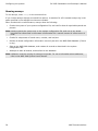
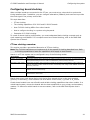
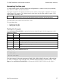
Revision history
Revision
Release date
Notes
1.0
May, 2002
NBS, based on 9000-6747-16, NACD 2002-1 GA
Last modified: May 16, 2002
Refer to the NMS web site (www.nmscommunications.com) for product updates and for information about NMS support policies, warranty
information, and service offerings.
2
NMS Communications
Table of Contents
Introduction ..................................................................................................................... 7
Overview of the CX 2000 board family.............................................................................. 9
CX 2000 product family features......................................................................................... 9
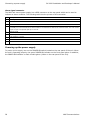
Power supply ..................................................................................................................12
Developer's cable kit ........................................................................................................12
Software components.......................................................................................................13
Natural Access..............................................................................................................13
NMS OAM ....................................................................................................................13
CX board plug-in...........................................................................................................14
NMS OAM configuration files...........................................................................................14
CDI service ..................................................................................................................15
CX driver software ........................................................................................................15
Installation summary .......................................................................................................16
Installing a CX 2000 board ............................................................................................. 17
System requirements .......................................................................................................17
Selecting a PCI chassis ..................................................................................................18
Board components ...........................................................................................................19
Installing the CX 2000 board.............................................................................................20
Terminating the H.100 bus.............................................................................................20
Installing the hardware..................................................................................................20
Connecting to station phones ............................................................................................22
Developer's cable kit .....................................................................................................24
Connecting a power supply............................................................................................. 25
Using the NMS rack mount power supply chassis .................................................................25
Normal configuration .....................................................................................................26
Redundant power supply configuration ............................................................................26
Rack mount considerations ............................................................................................27
Connecting the NMS power supply ..................................................................................27
Powering up the power supply ........................................................................................28
Using an alternative power supply .....................................................................................29
Power supply requirements ............................................................................................29
Connecting an alternative power supply...........................................................................30
Configuring the system .................................................................................................. 31
Referencing the CDI manager for Natural Access .................................................................31
Adding board configurations to the NMS OAM database ........................................................32
Configuring the system using oamsys.................................................................................33
Using board keyword files ..............................................................................................33
Creating a system configuration file for oamsys ................................................................34
Running oamsys ...........................................................................................................36
Changing configuration parameter settings .........................................................................37
Configuring ring cadences.................................................................................................38
Default ring cadences ....................................................................................................39
Configuring board clocking................................................................................................41
CT bus clocking overview ...............................................................................................41
Clocking capabilities ......................................................................................................42
CX 2000 clocking exceptions ..........................................................................................43
Configuring CT bus clocks with keywords .........................................................................43
Examples .....................................................................................................................45
Notes on modem connections............................................................................................48
Verifying the installation ................................................................................................ 49
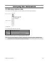
CX 2000 status indicator LEDs...........................................................................................49
NMS Communications
3
Table of Contents
CX 2000 Installation and Developer’s Manual
Verifying the board installation ..........................................................................................50
Verifying the board's operation..........................................................................................51
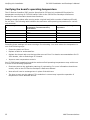
Verifying the board's operating temperature .......................................................................52
Implementing switching................................................................................................. 53
CX 2000 board switch model .............................................................................................53
Lucent T8100A switch blocking .......................................................................................54
Default connections for a standalone board .........................................................................55
Using the switching service ...............................................................................................56
Opening the switch .......................................................................................................56
Configuring local devices................................................................................................56
Accessing the line gain .....................................................................................................57
Getting the line gain......................................................................................................57
Setting the line gain ......................................................................................................59
Keyword reference ......................................................................................................... 61
Using keywords ...............................................................................................................61
Setting keyword values..................................................................................................61
Retrieving keyword values .............................................................................................62
Keyword summaries.........................................................................................................63
Editable keyword summary ............................................................................................63
Informational keyword summary ....................................................................................64
CX plug-in keywords .....................................................................................................64
Using the keyword reference .............................................................................................65
AutoStart........................................................................................................................66
AutoStop ........................................................................................................................67
Boards[x] .......................................................................................................................68
BootDiagnosticLevel .........................................................................................................69
Clocking.HBus.AutoFallBack ..............................................................................................70
Clocking.HBus.ClockMode .................................................................................................71
Clocking.HBus.ClockSource ...............................................................................................72
Clocking.HBus.ClockSourceNetwork ...................................................................................73
Clocking.HBus.FallbackClockSource....................................................................................74
Clocking.HBus.NetRefSource .............................................................................................75
Clocking.HBus.NetRefSpeed ..............................................................................................76
Clocking.HBus.SClockSpeed ..............................................................................................77
Clocking.HBus.Segment....................................................................................................78
Clocking.Type..................................................................................................................79
DebugMask .....................................................................................................................80
DefaultQslacFile...............................................................................................................81
DetectedBoards[x]...........................................................................................................82
Driver.Name ...................................................................................................................83
DSPFile ..........................................................................................................................84
DSP.Image .....................................................................................................................85
Eeprom.AssemblyRevision ................................................................................................86
Eeprom.Family ................................................................................................................87
Eeprom.MFGWeek ...........................................................................................................88
Eeprom.MFGYear .............................................................................................................89
Eeprom.SerialNum...........................................................................................................90
Eeprom.SoftwareCompatibility ..........................................................................................91
Eeprom.TestLevel ............................................................................................................92
Eeprom.TestLevelRev .......................................................................................................93
Encoding ........................................................................................................................94
ExternalRingerEnable .......................................................................................................95
HighBatteryEnable ...........................................................................................................96
Location.PCI.Bus .............................................................................................................97
Location.PCI.Slot .............................................................................................................98
4
NMS Communications
CX 2000 Installation and Developer’s Manual
Table of Contents
Location.Type..................................................................................................................99
LowBatteryEnable .......................................................................................................... 100
Name ........................................................................................................................... 101
Number ........................................................................................................................ 102
Product ........................................................................................................................ 103
Products[x] ................................................................................................................... 104
Ring.Cadences[x].Toff1 .................................................................................................. 105
Ring.Cadences[x].Toff2 .................................................................................................. 106
Ring.Cadences[x].Toff3 .................................................................................................. 107
Ring.Cadences[x].Ton1 .................................................................................................. 108
Ring.Cadences[x].Ton2 .................................................................................................. 109
Ring.Cadences[x].Ton3 .................................................................................................. 110
Ring.Period ................................................................................................................... 111
RingVoltageEnable ......................................................................................................... 112
SignalingLoopbackEnable................................................................................................ 113
State............................................................................................................................ 114
SwitchConnections......................................................................................................... 115
SwitchDriver.Name ........................................................................................................ 116
Version.Major................................................................................................................ 117
Version.Minor ................................................................................................................ 118
CX 2000 hardware specifications.................................................................................. 119
General Specifications .................................................................................................... 119
Host interface............................................................................................................. 119
Telephone interface..................................................................................................... 119
H.100 compliant interface ............................................................................................ 119
Environment ................................................................................................................. 120
Maximum board operating temperature ......................................................................... 120
Power requirements ....................................................................................................... 121
Telco power per board ................................................................................................. 121
Signaling module ........................................................................................................... 122
Compliance and approvals .............................................................................................. 123
EMC .......................................................................................................................... 123
Safety ....................................................................................................................... 123
Telecom..................................................................................................................... 123
Other hardware specifications...................................................................................... 125
Rack mount ringing power supply specifications ................................................................ 125
Standards ..................................................................................................................... 126
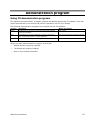
Demonstration program ............................................................................................... 127
Using CX demonstration programs ................................................................................... 127
Interactive test program: cditest ..................................................................................... 128
NMS Communications
5
Introduction
The CX 2000 Installation and Developer's Manual explains how to install and configure boards from
the CX 2000 family of products. Specifically, it explains how to:
•
Select a proper chassis for safety and heat considerations
•
Install a CX 2000 board in a chassis
•
Configure external power supplies
•
Install the driver software
•
Verify that the board has been installed correctly and is operating correctly
•
Perform CT bus switching with CX 2000 boards
NMS Communications
7
Overview of the CX 2000 board family
CX 2000 product family features
Boards in the CX 2000 family of products are station interfaces for Enterprise markets. They
provide analog interfaces to analog devices such as telephones, fax machines, modems, etc. within
a private network. They can be used to build such systems as Private Branch Exchanges, Automatic
Call Distributors, and IP-PBXs.
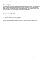
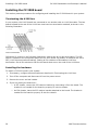
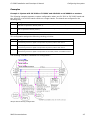
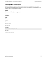
In a system containing CX 2000 products, any communication with the public network is performed
by trunk interface boards (such as CG 6000Cs or AG 4000s). CX 2000 or CX 2000C boards
communicate with these boards over the H.100 or H.110 bus (see the following illustration).
CX 2000 products have sufficient on-board DSP resources for simple, low-level call control
functions. More complex, resource-intensive operations (such as voice playing or recording) must
be performed by other boards (such as the CG 6000C or AG 4000).
Typical system including CX 2000 or CX 2000C boards
The CX 2000 product family consists of four board models. They differ in:
•
The chassis each was designed for
•
The number of stations each model supports
•
The method each model uses to provide ring voltage to station phones.
NMS Communications
9
Overview of the CX 2000 board family
CX 2000 Installation and Developer’s Manual
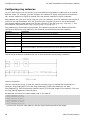
The following table lists and describes each board model:
Board model
Chassis type
CX 2000C-32
CompactPCI (main board and
rear transition board)
CX 2000C-32-R
CX 2000C-48
CX 2000-32
CompactPCI (main board and
rear transition board)
CompactPCI (main board and
rear transition board)
PCI
Features
•
Supports up to 32 stations
•
Maximizes airflow and
reduces heat
•
Uses only J5 for telco lines
•
Provides high ring capacity
•
Supports up to 32 stations
•
Maximizes airflow and
reduces heat
•
Uses only J5 for telco lines
•
Requires 24-32V DC talk
battery power supply only
•
Supports up to 48 stations
•
Offers highest density for
applications where number
of stations simultaneously
active is low
•
Uses J3 and J5 for telco
lines. (J3 must have
proper safety clearance.)
•
Provides high ring capacity
•
Supports up to 32 stations
•
Provides high ring capacity
Limitations
•
Requires external ring
voltage supply
•
Limited ring capacity (12
simultaneous ringing
phones)
•
Less than 2000 feet of
cable to phone
•
Requires external ring
voltage supply
•
Requires chassis features
described in the CX 2000C
Installation and
Developer's Manual
•
Limited to applications
where less than 24
stations are in continuous
operation, due to heat
issues
•
Requires external ring
voltage supply
•
Requires a chassis with air
flow considerations
described in Selecting a
PCI chassis
•
UL and CSA requirements
limit cabling to within the
building
CX 2000 and CX 2000C boards offer a standard set of station call control features. Functions such
as playing, recording, and conferencing are performed by the trunk interface boards or other
resource boards in the system.
10
NMS Communications
CX 2000 Installation and Developer’s Manual
Overview of the CX 2000 board family
The following table summarizes the features of each product in the family:
Feature
CX 2000C-32
CX 2000C-32-R
CX 2000C-48
CX 2000-32
Chassis type
CompactPCI
CompactPCI
CompactPCI
PCI
Number of ports
32
32
48
32
CT bus
H.110
H.110
H.110
H.100
Call center applications
Supported
Supported
NOT Supported
Supported
PBX applications
Supported
Supported
Supported
Supported
Detect on/off hook
Supported
Supported
Supported
Supported
Detect flash-hook
Supported
Supported
Supported
Supported
DTMF detection
Supported
Supported
Supported
Supported
DTMF generation
Supported
Supported
Supported
Supported
Dial tone
Supported
Supported
Supported
Supported
Call progress tones
Supported
Supported
Supported
Supported
CT bus switching API
Supported
Supported
Supported
Supported
Heart beat diagnostic
Supported
Supported
Supported
Supported
Transmit gain
Supported
Supported
Supported
Supported
Receive gain
Supported
Supported
Supported
Supported
Temperature sensors
Supported
Supported
Supported
Supported
On premise extensions
Supported
Supported
Supported
Supported
Off premise extensions
Supported
NOT Supported
Supported
NOT Supported
Wiring between buildings
Supported
Supported
Supported
NOT Supported
The PCI product is limited
to inside cabling, due to
both heat and safety
power cross certification.
Internal ringing supply
NOT Supported
Supported
Easy chassis selection
Supported
Supported
Hot Swap
Supported
Supported
NOT Supported
NOT Supported
NOT Supported
NOT Supported
Because the CX 2000C-48
exceeds the 32-line
CompactPCI specification,
selecting a chassis for
these applications has
special considerations. For
details, see CX 2000C
Installation and
Developer's Manual.
Selecting a PCI chassis with proper air
Supported
NOT Supported
flow is critical for multiple CX 2000-32
boards to operate. For details, see
Selecting a PCI chassis.
The CX 2000C fully supports the H.110 bus specification. The CX 2000 fully supports the H.100 bus
specification. Switching for both boards is implemented with the T8100A chip. The T8100A offers
full support for the H.110/H.100 bus within the H.110/H.100 architecture providing access to all
4096 slots on the bus.
On the boards, switch connections are allowed for up to 128 full duplex connections between local
devices and the bus. Non-blocking switch connections are allowed between local devices.
NMS Communications
11
Overview of the CX 2000 board family
CX 2000 Installation and Developer’s Manual
Power supply
To provide power for talk battery and for ringing station phones (if necessary), an external power
supply is required. NMS Communications supplies a rack mount power supply chassis that can
contain up to four interchangeable supply modules. Alternatively, you can obtain a power supply
from another source. You can connect the power supply to each board.
For more information on choosing and connecting power supplies, refer to Using the NMS rack
mount power supply chassis.
Developer's cable kit
To ease connecting telephones to CX 2000 boards, a developer's cable kit is available. It consists of
the following components:
•
Two RJ-21, twenty-five pair, 10 feet cables
•
Two breakout boxes RJ-21 to 25 RJ-11
For more information about the developer's cable kit, refer to Connecting to station phones.
12
NMS Communications
CX 2000 Installation and Developer’s Manual
Overview of the CX 2000 board family
Software components
CX 2000 boards require the following software components:
•
The Natural Access development environment that provides application programming
interfaces (APIs) for call control, voice store and forward, and switching.
•
NMS OAM (Operations, Administration, and Maintenance), a Natural Access service that
configures, administers, and maintains telephony resources in a system..
•
The CX 2000 software package that includes the:
•
CX board plug-in
•
NMS OAM configuration files
•
CDI service DLLs and libraries that provide the call control functions on CX 2000 and CX
2000C boards
•
Device driver and downloadable firmware
•
cxsw switching driver
Natural Access
Natural Access is a complete software development environment for voice applications. It provides
a standard set of voice functions grouped into logical services. Each service has a standard
programming interface. For more information about standard and optional Natural Access services,
refer to the Natural Access Developer's Reference Manual.
NMS OAM
NMS Operations, Administration, and Maintenance (OAM) service manages and maintains the
telephony resources in a system. These resources include hardware components (including CX
boards) and low-level board management software modules (such as clock management).
Using NMS OAM, you can:
•
Create, delete, and query the configuration of a component
•
Start (boot), stop (shut down), and test a component
•
Receive notifications from components
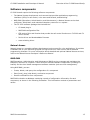
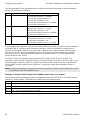
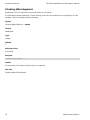
NMS OAM maintains a database containing records of configuration information for each
component, as shown in the following illustration. This information consists of parameters and
values.
NMS Communications
13
Overview of the CX 2000 board family
CX 2000 Installation and Developer’s Manual
NMS OAM components
Each NMS OAM database parameter and value is expressed as a keyword name/value pair (for
example, Encoding = MuLaw). You can query the NMS OAM database for keyword values for any
component. Keywords and values can be added, modified, or deleted.
Note: Before using NMS OAM or any of its related utilities, verify that ctdaemon is running. For
more information about ctdaemon, refer to the Natural Access Developer's Reference
Manual. For general information about NMS OAM and its utilities, refer to the NMS OAM
System User's Manual.
CX board plug-in
NMS OAM uses the CX board plug-in module to communicate with CX boards. The name of the CX
plug-in is cx.bpi. The file must reside in one of the following directories in order for NMS OAM to
load it when it starts up:
Operating system
Path to cx.bpi
Windows 2000
\nms\bin
UNIX
/opt/nms/bin
NMS OAM configuration files
NMS OAM uses two types of configuration files:
File Type
Description
System configuration
NMS OAM system configuration files contain a list of boards in the system and the name of one or
more board keyword files for each board.
Board keyword
NMS OAM board keyword files contain parameters to configure the board (refer to the following
illustration). These settings are expressed as keyword name and value pairs.
14
NMS Communications
CX 2000 Installation and Developer’s Manual
Overview of the CX 2000 board family
Sample keyword files are installed with Natural Access. You can reference these files in your
system configuration file or modify them.
NMS OAM configuration files
When you run the oamsys utility, it creates NMS OAM database records based on the contents of
the specified system configuration file and board keyword files. It then directs the OAM service to
start the boards, configured as specified. Refer to Configuring the system using oamsys for more
information about configuration files and oamsys.
CDI service
The CX Devices Interface (CDI) service is a Natural Access service that performs low-level stationoriented call control and board management functions for CX 2000 and CX 2000C boards. These
functions include tone generation, DTMF detection, signaling, on-board timer actuation,
temperature monitoring, power detection, and station module detection.
CX driver software
The following drivers are installed with Natural Access for operating CX 2000 boards:
Operating system
Driver names
Windows 2000
cxddrv.sys
UNIX
cx
cxsw
NMS Communications
15
Overview of the CX 2000 board family
CX 2000 Installation and Developer’s Manual
Installation summary
The following table summarizes the steps required to install CX 2000 hardware and software
components:
Step
Description
For details, refer to...
1
Ensure that your PC system meets the system requirements.
System requirements
2
Install the board and connect it to station phones.
Installing the CX 2000 board
3
Connect a power supply.
Connecting a power supply
4
Install Natural Access (including Hot Swap), CX drivers, and NMS CAS
protocols from the Natural Access CD.
The Natural Access installation booklet
5
Configure the system.
Configuring the system
6
Verify that your installation is operational.
Verifying the board installation
16
NMS Communications
Installing a CX 2000 board
System requirements
To install and use CX 2000 boards, your system must have
•
An available PCI bus slot.
•
The PCI version 2.2 compliant bus and BIOS.
•
Natural Access version 4.0 or later installed.
•
An uninterruptable power supply (UPS). Although a UPS is not strictly required, it is strongly
recommended for increased system reliability. The UPS does not need to power the PC video
monitor except in areas prone to severe lightning storms.
•
An H.100 bus cable if you are connecting to any other H.100 boards.
•
A grounded chassis with a three-prong power cord.
•
Adequate cooling for the chassis. See Selecting a PCI chassis for more information.
•
A power supply. For more information, refer to Using the NMS rack mount power supply
chassis or to Using an alternative power supply.
Caution:
Each CX 2000 board is shipped in a protective anti-static container. Leave the board in its container until you
are ready to install it. Handle the board carefully and hold it only by its handles. We recommend that you
wear an anti-static wrist strap connected to a good earth ground whenever you handle the board.
NMS Communications
17
Installing a CX 2000 board
CX 2000 Installation and Developer’s Manual
Selecting a PCI chassis
Use the following guidelines when choosing a chassis for the CX 2000 board:
•
CX 2000 boards must be oriented vertically on the backplane to aid convection cooling. Avoid
using a PC tower if you have more than two CX 2000 boards.
•
In a large system (five or more slots) use at least one fan for every four slots. Use fans with a
minimum rating of 40 cubic feet per minute (CFM) for blowing or drawing air lengthwise along
the boards.
•
In a smaller system (four or fewer slots) use fans that total at least 100 CFM for blowing or
drawing air lengthwise along the boards.
Each chassis is different, and cooling is affected by such factors as:
•
The distance between the fans on the boards
•
The total volume of the chassis
•
The pressure differential between the inside and outside of the chassis
These guidelines are for a typical application. In some cases, more airflow may be necessary to
ensure the board is operating at an acceptable temperature.
If you install an uninterrupted power supply, and use it to back up the NMS rack mount power
supply (described in Using the NMS rack mount power supply chassis), it should be rated for a
minimum of 1.8 kW.
WARNING:
18
This product will not boot in a PC chassis that does not conform to PCI specification version 2.2.
If a PC was made before 1999, it probably does not conform to this specification.
NMS Communications
CX 2000 Installation and Developer’s Manual
Installing a CX 2000 board
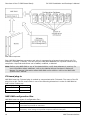
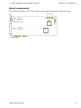
Board components
The following illustration shows where various components are located on a CX 2000 board:
CX 2000 board
NMS Communications
19
Installing a CX 2000 board
CX 2000 Installation and Developer’s Manual
Installing the CX 2000 board
This section presents procedures for configuring and installing the CX 2000 board in your system.
Terminating the H.100 bus
In your system, the H.100 boards are connected to one another with an H.100 bus cable. The two
boards located at the end of the H.100 bus must have bus termination enabled, as shown in the
following illustration.
CT bus termination
DIP switch S1 (shown in the following illustration) controls the H.100 bus termination. The DIP
switch is located on the component side of the CX 2000 board. By default, all switches are set to
OFF (H.100 bus termination disabled). Setting all S1 switches to ON enables H.100 bus
termination. Set all S1 switches to ON for the boards that are on the ends of the H.100 bus.
Installing the hardware
To install a CX 2000 board in your system:
1. If necessary, configure bus termination as described in Terminating the H.100 bus.
2. Turn off the computer and disconnect it from the power source.
3. Remove the cover and set it aside.
4. If you are placing the board into:
20
•
A PCI chassis, remove the PCI retainer bracket by unscrewing it from the board. The
bracket is not needed for the board to properly fit into the chassis.
•
An ISA chassis, leave the PCI retainer bracket attached to the board. The bracket is
needed for the board to properly fit into the chassis.
NMS Communications
CX 2000 Installation and Developer’s Manual
Installing a CX 2000 board
PCI retainer bracket
5. Arrange the CX 2000 board and other H.100 boards in adjacent PCI bus slots.
6. Make sure each board's PCI bus connector is seated securely in a slot.
7. Secure the end bracket on the CX 2000 board to the PC.
8. Connect the H.100 bus cable to the CX 2000 board.
9. If you have multiple H.100 boards, connect the H.100 bus cable to each of the H.100 boards.
10. Replace the cover, and connect the computer to its power source.
11. Install the CX software as described in the Natural Access installation booklet.
12. Connect station phones to the board as described in Connecting to station phones.
13. Connect a power supply to the board as described in Using the NMS rack mount power supply
chassis or to Using an alternative power supply.
NMS Communications
21
Installing a CX 2000 board
CX 2000 Installation and Developer’s Manual
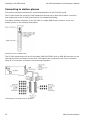
Connecting to station phones
This section provides instructions for connecting telephones to the CX 2000 board.
The CX 2000 board can connect to local telephones through up to 2000 feet of cable. Lines from
local telephones to the CX 2000 board cannot run outside the building.
The station interface connector on the CX 2000 is a single MDR 68 pin connector on the end
bracket (shown in the following illustration):
Connectors on a CX 2000 board
The CX 2000 board ships with one 3-foot cable (NMS P/N 32590) with an MDR 68 connector on one
end and two RJ-21 connectors on the other. The stations are connected to the RJ-21 connectors
using 66 or 110 blocks, as shown in the following illustration:
Connecting the CX 2000 board to stations
22
NMS Communications
CX 2000 Installation and Developer’s Manual
Installing a CX 2000 board
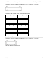
The following illustration shows the pin locations for each RJ-21 connector on the cable:
Pinouts for MDR-68 connector on CX 2000 board
The following table shows the pinouts for the MDR 68 connector:
Station
Ring pin
Tip pin
Station
Ring pin
Tip pin
1
2
3
17
36
37
2
4
5
18
38
39
3
6
7
19
40
41
4
8
9
20
42
43
5
10
11
21
44
45
6
12
13
22
46
47
7
14
15
23
48
49
8
16
17
24
50
51
9
18
19
25
52
53
10
20
21
26
54
55
11
22
23
27
56
57
12
24
25
28
58
59
13
26
27
29
60
61
14
28
29
30
62
63
15
30
31
31
64
65
16
32
33
32
66
67
Note: Pins 1 and 68 are not used.
The following illustration shows the pin locations for each RJ-21 connector on the cable:
Cable (NMS P/N 32590) Connector pinouts
NMS Communications
23
Installing a CX 2000 board
CX 2000 Installation and Developer’s Manual
The following table lists the pinouts for the first RJ-21 connector on the cable:
Station
Ring pin
Tip pin
Station
Ring pin
Tip pin
1
1
26
13
13
38
2
2
27
14
14
39
3
3
28
15
15
40
4
4
29
16
16
41
5
5
30
17
17
42
6
6
31
18
18
43
7
7
32
19
19
44
8
8
33
20
20
45
9
9
34
21
21
46
10
10
35
22
22
47
11
11
36
23
23
48
12
12
37
24
24
49
Note: Pins 25 and 50 are not used on this connector.
The following table lists the pinouts for the second RJ-21 connector on the cable:
Station
Ring pin
Tip pin
25
1
26
26
2
27
27
3
28
28
4
29
29
5
30
30
6
31
31
7
32
32
8
33
Note: Pins 9-25 and 34-50 are not used on this connector.
Developer's cable kit
To help you get started, NMS provides an optional developer's cable kit (NMS P/N 80659). The kit
contains two 10-foot RJ-21 cables and two breakout boxes. Each breakout box connects one RJ-21
to 24 standard RJ-11 (POTS) jacks for individual phones. You can use the cables to connect to the
breakout boxes or to standard 66 or 110 blocks.
All components of the developer's cable kit sold by NMS are also commercially available from
telephone product distributors such as Graybar and Anixter. These distributors can provide
variations in cable lengths.
24
NMS Communications
Connecting a power supply
Using the NMS rack mount power supply chassis
To supply talk battery power to the station phones and to power ringing (if necessary), an external
power supply is required.
NMS supplies a rack mount power supply chassis that can contain up to four interchangeable
supply modules. Each module can power up to two CX 2000 boards. Four modules produce a total
combined output of 8.8A for
-48V and -30V/-24V. The ring output total is 0.68A. The supply outputs are isolated from ground
and rely on the CX 2000 board to ground the return line. This provides the best EMI performance.
(See the following illustration.)
Rack mount power supply chassis and modules
The power supply autoranges for global power standards, and can be configured for local ring
frequency standards to satisfy global deployment requirements.
Note: Power supplies NMS P/N 2961 and NMS P/N 31468 used with S Connect and CX 1000
products are not compatible with CX 2000 boards.
NMS Communications
25
Connecting a power supply
CX 2000 Installation and Developer’s Manual
Normal configuration
The following table indicates the number of power supply chassis and modules you will need, based
upon the number of CX 2000 boards in your system. The table assumes a normal configuration, in
which all stations are active on each board. Sufficient ring signal is supplied so that for short (not
continuous) peak demand periods, more than 20 phones rated at 1.0 REN can ring simultaneously.
Number of CX
boards
Power supply chassis required
1
1
0
2
1
0
3
1
1
4
1
1
5
1
2
6
1
2
7
1
3
8
1
3
(Each chassis includes one power supply
module)
Expansion modules
required
Redundant power supply configuration
To provide redundancy, or to supply additional ring power to your system, you can install one more
power supply module then you need. The module-to-board connectors on all modules are wired in
parallel, so if one module fails, another module supplies power to the first module's board
connector. This helps ensure uninterrupted power to any connected boards in the unlikely event
that a module fails.
If you connect the power supply to a UPS, the contribution of a fully populated power supply
chassis is 1.8 kW.
The following table indicates the number of power supply chassis modules you will need, in a
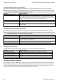
configuration in which an extra power supply module is installed:
Number of CX boards
Power supply chassis required
Expansion modules required
(Each chassis includes one power supply
module)
1
1
1
2
1
1
3
1
2
4
1
2
5
1
3
6
1
3
7
N/A
N/A
8
N/A
N/A
When you have seven or eight CX boards, there is a maximum of four modules per chassis.
26
NMS Communications
CX 2000 Installation and Developer’s Manual
Connecting a power supply
Rack mount considerations
Consider the following items when installing a power supply in a rack:
•
Do not block the power supply vents, or otherwise restrict airflow when installing the unit into
a rack.
•
Ensure that the rack is properly secured, so the rack is stable and cannot easily tip.
•
Ensure that the electrical requirements of the system do not exceed the capacity of the
electrical circuit.
•
If an uninterrupted power supply is used to back up the rack mount supply, it should be rated
for at least 1.8 kW.
Note: In the unlikely event that the power supply current exceeds the current rating, the power
supply output clamps to zero to protect the supply. The power supply may need to be turned
off momentarily and then turned back on to restore normal operation.
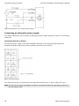
Connecting the NMS power supply
You can connect power supply modules directly to CX 2000 boards.
NMS supplies two cables for these connections:
•
NMS P/N 32523 (shipped with the module) - a cable with a male 8-pin Positronic connector on
one end (to connect to the module), and two 10-pin MOLEX mini junior connectors on the
other end to connect to the TELCO POWER connectors on CX 2000 boards.
•
NMS P/N 32522 (can be ordered separately) - a cable with a male 8-pin Positronic connector
on one end (to connect to the module), and #8 spade lugs on the other end to connect to the
chassis telecom power bus.
Connecting directly to boards
To connect the NMS power supply directly to each board:
1. On the power supply chassis, set the VOLTAGE switch to 24V.
2. On the power supply, set the FREQUENCY switch to a ringing frequency (default = 20 Hz).
The default ringing frequency setting (20 Hz) will operate correctly in most applications.
However, you can change this setting if a station does not ring when directed, or to change
the sound of the ringer to match that of other devices in the target country or region.
WARNING:
Do not change the frequency or voltage while the power supply is operating.
Plug the Y end of the cable (NMS P/N 32523) into the TELCO POWER connectors on the CX 2000
boards.
Plug the other end of the cable into the power supply.
When you have finished configuring the power supply, plug it into a power source.
NMS Communications
27
Connecting a power supply
CX 2000 Installation and Developer’s Manual
Alarm signal connector
The NMS rack mount power supply has a DB9 connector on the rear panel which can be used to
indicate an alarm condition. The following table lists the pinouts of this connector:
Pin
Description
1
Chassis ground
2
1.5K resistor to +12 V DC
3
4.7K resistor to +5 V DC
4
Alarm signal output. This is an open collector NPN transistor with the emitter connected to COMMON. The transistor
is normally on. It is turned off for an alarm condition. The transistor is rated for 20 V DC and 5 mA. The 4.7K resistor
on pin 3 or pin 7 can provide pull-up to +5 V DC.
5
Optional signal
6
+5 V DC @ 3 mA
7
4.7K resistor to +5 V DC
8
COMMON
9
COMMON
Powering up the power supply
To power up the supply, turn on the POWER ON switch located on the rear panel of the unit. When
the unit is operating properly, the green POWER ON indicator on the front panel glows. In addition,
the POWER ON indicator on each module glows (visible on the rear panel of the unit).
28
NMS Communications
CX 2000 Installation and Developer’s Manual
Connecting a power supply
Using an alternative power supply
You can use a power supply other than the NMS power supply. This power supply must provide:
•
DC voltage to provide talk battery power to the station phones
•
AC and DC ring voltage, if your application involves ringing station phones. The AC voltage
provides the ringing power. The DC voltage provides loop current that signals the CX board
when the phone goes on or off hook.
This section specifies the power supply requirements for different boards, and describes how to
connect an alternative power supply.
Note: If you are using CX 2000-32-R boards with the on-board ringing option enabled, you do not
need to provide external ring voltage. However, you still need to provide the talk battery
power.
Power supply requirements
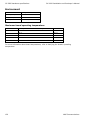
The tables in the following sections specify power supply requirements for different boards, cable
lengths and resistive loads.
Cables between the power supply and the board must be rated for 2A per board or greater. Twisted
pair cabling is recommended for noise reduction.
WARNING:
In the worst case, the ring voltage must not exceed 92 V AC, and the DC voltage must not
exceed 52 V DC.
Note: The AG 2000 power supply can be substituted for the rack mount supply for one CX 2000
board. The cable supplied with the AG 2000 power supply will mate with the connector on
the board.
CX 2000 power supply requirements
For CX 2000 boards, AC voltage is required only if you are enabling ringing of station phones.
Recommended output
Length of 24
AWG cable
Max resistive
load
Talk
Battery
Ring voltage
(only if ringing
required)
0 to 2000 feet
600 Ohms
-24VDC
55 to 89VAC and -24VDC
> 2000 feet
Not supported.
The ring signal circuitry in the power supply must be equivalent to the schematic shown in the
following illustration:
NMS Communications
29
Connecting a power supply
CX 2000 Installation and Developer’s Manual
Ring signal schematic (for CX 2000 power supply)
Connecting an alternative power supply
This section describes how to connect an alternative power supply directly to board, or to a telecom
power bus.
Connecting directly to boards
Connect the power supply to the TELCO POWER connector on the rear transition board. the
following illustration shows the power connector pinouts for the CX 2000:
Power connector pinouts
The mating connector is Molex 43025-1000 with Molex 43030-0001 or Molex 43030-007 pins.
Note: If only one DC output is available, it must be connected to both the high battery input and
the low battery input.
30
NMS Communications
Configuring the system
Referencing the CDI manager for Natural Access
For the CDI manager component to be available to the Natural Access server when it boots, it must
be referenced in your Natural Access configuration file, cta.cfg, as shown below:
[ctasys]
Service =
Service =
Service =
Service =
Service =
Service =
Service =
Service =
Service =
ncc,
adi,
cdi,
ais,
dtm,
ppx,
swi,
vce,
oam,
adimgr
adimgr
cdimgr
aismgr
adimgr
ppxmgr
swimgr
vcemgr
oammgr
For more information about cta.cfg and its contents, refer to the Natural Access Developer's
Reference Manual.
NMS Communications
31
Configuring the system
CX 2000 Installation and Developer’s Manual
Adding board configurations to the NMS OAM database
For the NMS OAM software to be able to configure and start the boards, each board must have a
separate set of configuration parameters and values in the NMS OAM database. Each parameter
and value is expressed as a keyword name/value pair (for example, Encoding = MuLaw).
The following utilities shipped with NMS OAM allow you to set up the database:
Utility
Description
oamsys
Performs system-wide configuration and startup of boards. Configures the NMS OAM database based on system
configuration files you supply. Then attempts to start all boards listed in the database.
oamcfg
Provides greater access to individual NMS OAM configuration functions.
oaminfo
Displays keywords and settings for one or more components. Can also set individual keywords.
Note: Applications can use OAM service functions to retrieve and modify configuration parameters.
For more information, refer to the NMS OAM Service Developer's Reference Manual.
For general documentation of NMS OAM utilities, refer to the NMS OAM System User's Manual.
32
NMS Communications
CX 2000 Installation and Developer’s Manual
Configuring the system
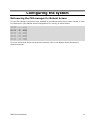
Configuring the system using oamsys
To configure a system using the oamsys utility:
1. Install the boards as described in Installing the CX 2000 board.
2. Create a board keyword file for each board, containing keywords and values to configure the
board.
3. Determine the PCI bus and slot locations of the boards, using the pciscan utility. For more
information about pciscan, refer to the NMS OAM System User's Manual.
4. Create a system configuration file describing the overall board configuration. In this file, give
each board a unique name and board number, and assign it a board keyword file.
5. Use oamsys to create records for your boards in the NMS OAM database based on the system
configuration file, and to start all installed boards.
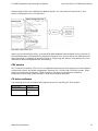
Using board keyword files
A board keyword file contains a list of parameters and values to configure a board. The board
keyword file for each board is assigned to the board in another file, called a system configuration
file. When oamsys runs, it creates a record for each board in the NMS OAM database, and stores
the parameters and values of the board. It then starts the board, configured as described in the
database. (See the following illustration.)
NMS OAM configuration files
A sample board keyword file, cx2000.cfg, is installed by the CX 2000 software installation program.
You can copy this file and modify it. The file is located in one of the following paths, depending
upon your operating system:
Operating system
Path to cx2000.cfg
Windows 2000
\nms\cx\cfg
UNIX
/opt/nms/cx/cfg
NMS Communications
33
Configuring the system
CX 2000 Installation and Developer’s Manual
You can customize additional features:
•
Configure the ring cadence (see Configuring ring cadences)
•
Specify the H.100 clock configuration (see Configuring board clocking)
The contents of cx2000.cfg are shown in the following example. For information on specific
keywords, refer to Using keywords. For general information about NMS OAM board keyword files,
refer to the NMS OAM System User's Manual.
#
# Standalone operation
#
Clocking.HBus.ClockMode
= STANDALONE
Clocking.HBus.ClockSource = OSC
#
# Master the CT Bus (drive clock A)
#
#Clocking.HBus.ClockMode
= MASTER_A
#Clocking.HBus.ClockSource = OSC
#
# Slave to the CT Bus (slave from clock A)
#
#Clocking.HBus.ClockMode
= SLAVE
#Clocking.HBus.ClockSource = A_CLOCK
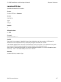
Creating a system configuration file for oamsys
When your board keyword file(s) are complete, create a system configuration file describing the
overall configuration of your system, and assigning a board keyword file to each board. oamsys
creates records in the NMS OAM database for your boards based on this file.
The system configuration file is typically named oamsys.cfg. By default, oamsys looks for a file with
this name when it starts up.
Refer to the NMS OAM System User's Manual for specific information on the syntax and structure of
this file.
34
NMS Communications
CX 2000 Installation and Developer’s Manual
Configuring the system
The following chart describes the CX 2000 board-specific settings to include in the file for each
board:
Keyword
Description
Allowed values for CX 2000 products
[name]
The name of the board, used to refer to the board in
software. The board name must be unique.
Any string, in square brackets [].
Product
The name of the board product.
CX 2000-16
CX 2000-32
CX_2000
Number
The board number that your Natural Access
application associates with the board.
Any integer from 0 to 31. Each board's number must
be unique.
Bus
The PCI bus number. The bus:slot location for each
board must be unique.
Values returned by pciscan.
Slot
The PCI slot number. The bus:slot location for each
board must be unique.
Values returned by pciscan.
File
The name of the board keyword file containing
settings for the board.
The name of the board keyword file you want to
assign the board.
You can specify more than one file after the File
keyword:
File = mya.cfg myb.cfg myc.cfg
Alternatively, you can specify the File keyword more
than once:
File = mya.cfg
File = myb.cfg
File = myc.cfg
Board keyword files are sent in the order listed. The
value for a given keyword in each file overrides any
value specified for the keyword in earlier files.
Keywords and values can also be specified directly in the system configuration file. This is often
useful if your board configurations are identical, except for one or two parameters (such as
clocking information).
Sample system configuration file
The following sample system configuration file describes two CX 2000 boards:
•
Board number 0 is located at bus 0, slot 15. It is assigned a keyword file named cxmaster.cfg.
•
Board number 1 is located at bus 0, slot 16. It is assigned a keyword file named cx-slave.cfg.
[CX-0]
Product
Number
Bus
Slot
File
=
=
=
=
=
CX 2000-32
0
0
15
c:\nms\cx\cfg\cx-master.cfg
[CX-1]
Product
Number
Bus
Slot
File
=
=
=
=
=
CX 2000-32
1
0
16
c:\nms\cx\cfg\cx-slave.cfg
NMS Communications
35
Configuring the system
CX 2000 Installation and Developer’s Manual
Running oamsys
To run oamsys, enter oamsys on the command line.
If you invoke oamsys without command line options, it searches for a file named oamsys.cfg in the
paths specified in the AGLOAD environment variable.
When invoked with a valid filename, oamsys does the following:
•
Checks the syntax of your system configuration file, and verifies that all required keywords are
present.
Note: oamsys checks the syntax only on the system configuration file, and not on any board
keyword files referenced in the system configuration file. oamsys reports all syntax errors it
finds.
•
Checks for uniqueness of board name, number, and bus/slot.
•
Deletes all board configuration information currently stored in the NMS OAM database (if there
is any).
•
Sets up the NMS OAM database, and creates all records as described in the system
configuration file.
•
Attempts to start all boards, as described in the database.
Note: ctdaemon must be running for oamsys to operate. For more information about ctdaemon,
refer to the NMS OAM System User's Manual.
36
NMS Communications
CX 2000 Installation and Developer’s Manual
Configuring the system
Changing configuration parameter settings
Once you have initialized the database with oamsys, you can make further parameter changes in
any of the following ways:
•
Modify the board keyword file for the board, make sure the name is correctly specified in the
File statement in oamsys.cfg, and run oamsys again.
•
Specify parameter settings using the oamcfg utility. For information about this utility, refer to
the NMS OAM System User's Manual.
•
Specify the settings using OAM service functions. (See the NMS OAM Service Developer's
Reference Manual for more information.)
NMS Communications
37
Configuring the system
CX 2000 Installation and Developer’s Manual
Configuring ring cadences
For a CX 2000 board, you can specify up to three different ring patterns (cadences) to be used at
different times. For example, you can configure one cadence to signify an extension-to-extension
call, another cadence to signify an outside call, and another cadence to signify a callback.
Each cadence can have up to three rings per cycle. For example, your first cadence could consist of
one 2000 ms ring followed by 4000 ms of silence (like a typical ring tone in the United States).
Your second cadence could sound more like the ring tone in the UK (ring ring...ring ring...). Your
third cadence could have three rings (ring ring ring...ring ring ring...).
Ring cadencing is controlled using keywords. The cadencing keywords have default values that
specify three distinctive ring cadences. The following keywords determine each cadence:
Keyword
Description
Ring.Cadences[x].Ton1
Determines the length (in ms) of the first ring in the cadence.
Ring.Cadences[x].Toff1
Determines the length (in ms) of the silence between the first and second rings in the cadence.
Ring.Cadences[x].Ton2
Determines the length (in ms) of the second ring in the cadence.
Ring.Cadences[x].Toff2
Determines the length (in ms) of the silence between the second and last rings in the cadence.
Ring.Cadences[x].Ton3
Determines the length (in ms) of the last ring in the cadence.
Ring.Cadences[x].Toff3
Determines the length (in ms) of the silence between the last ring in the cadence and the first
ring of the next cadence. This value must be equal to 2/3 of the total length of the cadence.
Ring.Period
Must be set to the total length of the cadence (in ms).
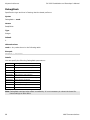
The following illustration illustrates the role of each keyword in determining a cadence:
Cadence components
You can omit the third ring, or both the second and third rings, by setting their keywords to 0.
However, Ring.Cadences[x].Ton1 and Ring.Cadences[x].Toff3 must always be set. Also,
Ring.Cadences[x].Toff3 must always equal at least 2/3 of the total length of the cadence. This is so
the ring phasing algorithm works correctly.
All cadences must be of the same length; that is, the total of
+
+
+
+
+
Ring.Cadences[x].Ton1
Ring.Cadences[x].Toff1
Ring.Cadences[x].Ton2
Ring.Cadences[x].Toff2
Ring.Cadences[x].Ton3
Ring.Cadences[x].Toff3
... must be the same for each cadence. Set the Ring.Period keyword to this length.
38
NMS Communications
CX 2000 Installation and Developer’s Manual
Configuring the system
Default ring cadences
The cadencing keywords have default values that specify three distinctive ring cadences. The
following table lists the default values for the keywords:
x
Ton1
Toff1
Ton2
Toff2
Ton3
Toff3
Total ms
Ring pattern
0
2000
0
0
0
0
4000
6000
ring...(silence)...
1
600
800
600
0
0
4000
6000
ring...ring...(silence)...
2
400
400
400
400
400
4000
6000
ring...ring...ring...(silence)...
The following illustration, the following illustration, and the following illustration illustrate the three
default cadences:
Default cadence (x=0)
Default cadence (x=1)
NMS Communications
39
Configuring the system
CX 2000 Installation and Developer’s Manual
Default cadence (x=2)
40
NMS Communications
CX 2000 Installation and Developer’s Manual
Configuring the system
Configuring board clocking
When multiple boards are connected to the CT bus, you must set up a bus clock to synchronize
timing between them. In addition, you can configure alternative (fallback) clock sources to provide
the clock signal if the primary source fails.
This topic describes:
•
CT bus clocking.
•
The clocking capabilities of CX 2000 and CX 2000C boards.
•
How CX 2000 clocking differs from other boards.
•
How to configure clocking in a system using keywords.
•
Examples of CX 2000 clocking.
To create a robust clocking configuration, you must understand basic clocking concepts such as
clock mastering and fallback. For a complete overview of board clocking, refer to the NMS OAM
System User's Manual.
CT bus clocking overview
This section provides a generalized discussion of CT bus clocking.
Note: The CX 2000 board does not implement all of the aspects of clocking described here. Refer
to Clocking capabilities to learn the capabilities which apply to these boards.
Boards in a CT bus system can be configured in any of the following modes:
Board mode
Description
Primary clock master
Drives the primary timing reference for boards connected to the CT bus. It can switch between
two specified timing sources in order to maintain the primary timing reference.
Secondary clock master
Drives the secondary timing reference. If both of the primary clock master's timing references
fail, the secondary master continues to drive a secondary clock using a clock fallback source as
its timing reference.
Clock slave
References its timing from the primary clock master. Can use the secondary clock master as a
fallback source of clock timing.
Standalone
Does not reference the primary or secondary master, and consequently cannot make switch
connections to the CT bus.
Boards that act as clock slaves derive their timing from signals driven by the clock masters
(primary or secondary). Clock masters can drive either of two clocks, A_CLOCK or B_CLOCK.
Certain board models have more flexible and reliable clocking capabilities than other models. In a
mixed board system, choose the boards with the best capabilities as your primary and secondary
masters. To determine which boards to use as masters, refer to the NMS OAM System User's
Manual.
NMS Communications
41
Configuring the system
CX 2000 Installation and Developer’s Manual
Timing references
Clock masters (primary or secondary) can synchronize their own timing signals from the following
sources:
Timing reference
source
Description
NETWORK
A signal originating within the public network, and entering the system through a digital trunk.
NETREF
A clock signal broadcast on the bus by another device, which can be used by a clock master as a
timing reference from which to synchronize A_CLOCK or B_CLOCK.
NETREF2
H.110 only
OSC
A signal originating from a board's oscillator.
For details on configuring bus clocks, refer to the NMS OAM System User's Manual or the ECTF
H.110 Hardware Compatibility Specification: CT Bus R1.0.
Clock fallback
The CT bus supports a system of clock fallback that allows the system to use alternate timing
references when one or more sources fail.
To enable clock fallback, set Clocking.HBus.AutoFallBack = YES. If clock fallback is disabled, the
application must perform all clocking changes.
To implement clock fallback:
1. Configure a primary clock master to drive the CT bus clock (A clock or B clock) based on a
network timing reference. All slave boards will synchronize their timing through this clock.
2. Configure a secondary clock master to use the signal from the primary clock to drive the
alternate CT bus clock (in other words, if the primary master drives A_CLOCK, configure the
secondary master to drive B_CLOCK based on A_CLOCK, or vice versa).
3. Specify a fallback network timing reference for the secondary clock master to use in the event
the primary clock master fails.
4. Configure all slave boards to specify the secondary clock master as their clock fallback source.
5. When the boards are configured in this way, the secondary clock master continues to drive the
secondary clock (based on its own network timing reference) if the primary clock master fails.
Slave boards within the system fall back to synchronize their timing from the secondary clock
master.
Note: CT bus clock fallback establishes a redundant system of timing references for the CT bus. It
does not create an autonomous clock timing environment. When clock fallback occurs, you
must intervene to reset system clocking before the all of the specified fallback timing
references are exhausted. If all of the timing references specified for the primary and
secondary clock masters fail (and no intervention takes place), boards on the system default
to standalone mode.
Clocking capabilities
CX 2000 boards do not have any direct access to an external source to derive a timing reference.
Thus the NETWORK timing reference is not directly available to these boards. The only timing
source available to CX 2000 boards is OSC.
Note: It is also possible to configure a CX 2000 board to use NETREF as a timing reference.
However, a simpler solution is to have the board driving NETREF serve as the clock master
instead, and eliminate use of these signals altogether.
42
NMS Communications
CX 2000 Installation and Developer’s Manual
Configuring the system
If another board has access to an outside clock signal, use this board as the clock master. CX 2000
boards are best used as clock masters only if none of the boards on the H.100 bus have any access
to an outside digital clock signal (for example, if your system contains only boards with analog
trunk interfaces). In this case, the CX 2000 board can drive A_CLOCK or B_CLOCK using its
internal oscillator (OSC) as the timing reference.
CX 2000 clocking exceptions
CX 2000 clocking differs from other boards in the following ways.
There are four watchdogs in the T8100A: A_CLOCK, B_CLOCK, NR1, and NR2. All of the watchdogs
are cleared by a single bit in a command register. In a fallback situation, clearing the watchdogs
results in reverting to the original clock source. When fallback is enabled and the watchdog for the
primary clock source triggers, the CX 2000 latches current and future watchdog errors until the
next MVIP95_CMD_CONFIG_BOARD_CLOCK command is received. This command can be issued
directly to the switching driver or indirectly by the OAM clock manager's apply keyword.
If, for example, A_CLOCK failed and a slaving CX 2000 falls back to B_CLOCK, and if B_CLOCK
were to go bad momentarily and recover, the CX 2000 would latch both clocks as bad until the
board is reconfigured even though B_CLOCK recovered.
If no clock sources are available to a SLAVE-mode CX 2000, the on-board DSP will stall and calls
may be dropped. Normal operation will resume with the resumption of system clock.
Configuring CT bus clocks with keywords
The CX 2000 board keywords allow you to configure the board in the following ways:
•
System primary clock master
•
System secondary clock master
•
Clock slave
•
Standalone board
•
You can also use board keywords to establish clock fallback sources.
The following sections describe how to use board keywords to specify clocking configurations on
multiple-board or multiple-chassis systems.
To configure clocking, set the following keywords for each board:
Keyword
Description
Clocking.HBus.ClockSource
Specifies the source from which a board derives its timing.
Clocking.HBus.ClockMode
Specifies the CT bus clock mode for the board (for example, A_CLOCK master,
B_CLOCK master, slave or standalone).
Clocking.HBus.AutoFallBack
Enables or disables clock fallback on the board.
Clocking.HBus.FallbackClockSource
Specifies an alternate clock reference to use when the primary clock source fails.
NMS Communications
43
Configuring the system
CX 2000 Installation and Developer’s Manual
Configuring the primary clock master
Use the following keyword settings to configure a CX 2000 board as the primary clock master:
Note: A CX 2000 should not be used as primary or secondary clock master unless no board in the
system has access to an external timing reference.
Keyword
CX board setting
Clocking.HBus.ClockSource
OSC
You can also set this keyword to NETREF. However, you should use these settings
only if another board has access to an external timing reference, and the CX board
must act as clock master. This configuration is not recommended.
Clocking.HBus.ClockMode
MASTER_A or MASTER_B
Clocking.HBus.AutoFallBack
YES if Clocking.HBus.ClockSource is set to NETREF. Otherwise, set to NO.
Clocking.HBus.FallbackClockSource
A timing reference other than the one specified with Clocking.HBus.ClockSource:
NETREF or OSC.
Configuring the secondary clock master
Use the following keyword settings to configure a CX 2000 board as the secondary clock master:
Note: A CX 2000 should not be used as primary or secondary clock master unless no board in the
system has access to an external timing reference.
Keyword
CX board setting
Clocking.HBus.ClockSource
The bus clock driven by the primary master: A_CLOCK or B_CLOCK.
Clocking.HBus.ClockMode
The bus clock not driven by the primary master (for example, MASTER_B if the
primary master is set to MASTER_A).
Clocking.HBus.AutoFallBack
YES
Clocking.HBus.FallbackClockSource
Any timing reference not used by the primary clock master: NETREF or OSC.
Configuring clock slaves
Use the following keyword settings to configure a CX 2000 board as a clock slave:
Keyword
CX board setting
Clocking.HBus.ClockMode
SLAVE to indicate that the board does not drive any CT bus clock.
Clocking.HBus.ClockSource
A_CLOCK or B_CLOCK.
Clocking.HBus.AutoFallBack
YES
Clocking.HBus.FallbackClockSource
Set to the bus clock driven by the secondary master (A_CLOCK or B_CLOCK.
Configuring standalone boards
To configure a board in standalone mode so the board references its own clocking information, set
Clocking.HBus.ClockMode to STANDALONE. In standalone mode, the board uses its own oscillator
as its timing signal reference. However, the board cannot make switch connections to the CT bus.
Switching commands involving CT bus streams will return an error.
44
NMS Communications
CX 2000 Installation and Developer’s Manual
Configuring the system
Examples
Example 1: System with CX 2000 or CX 2000C and AG 4000s or AG 4000Cs as masters
The following example assumes a system configuration where one CX 2000 or CX 2000C board and
two AG 4000 or AG 4000C boards reside on a single chassis. The boards are configured in the
following way:
Board
Configuration
Board 0
AG 4000 or AG 4000C board. Primary bus master. Drives A_CLOCK, based on signal from network (trunk 1).
Falls back to signal from network (trunk 3).
Board 1
AG 4000 or AG 4000C board. Secondary bus master. Drives B_CLOCK, based on signal from A_CLOCK. Falls
back to signal from network (trunk 2).
Board 2
CX 2000 or CX 2000C board. Clock slave to A_CLOCK (auto-fallback enabled).
This configuration assigns the following clocking priorities:
Priority
First
Timing reference
Board 0, digital trunk 1.
A network signal from a digital trunk provides the primary master clock source.
Second
Board 0, digital trunk 3.
A network signal from a digital trunk provides the primary master clock source.
Third
Board 1, digital trunk 2.
A network signal from a digital trunk provides the secondary master clock fallback source.
The following illustration illustrates this configuration:
Sample board clocking configuration
NMS Communications
45
Configuring the system
CX 2000 Installation and Developer’s Manual
The following table shows keywords used to configure the boards according to the configuration
shown in the following illustration.
Board
Role
Clocking keyword settings
0
Primary clock master
Clocking.HBus.ClockMode = MASTER_A
Clocking.HBus.ClockSource = NETWORK
Clocking.HBus.ClockSourceNetwork = 1
Clocking.HBus.AutoFallBack = YES
Clocking.HBus.FallBackClockSource = NETWORK
Clocking.HBus.FallBackNetwork = 3
1
Secondary clock master
Clocking.HBus.ClockMode = MASTER_B
Clocking.HBus.ClockSource = A_CLOCK
Clocking.HBus.AutoFallBack = YES
Clocking.HBus.FallBackClockSource = NETWORK
Clocking.HBus.FallBackNetwork = 2
2
Clock slave
Clocking.HBus.ClockMode = SLAVE
Clocking.HBus.ClockSource = A_CLOCK
Clocking.HBus.AutoFallBack = YES
Clocking.HBus.FallBackClockSource = B_CLOCK
In this configuration, Board 0 is the primary clock master and drives A_CLOCK. All slave boards on
the system use A_CLOCK as their first timing reference. Board 0 references its timing from a
network timing signal received on its own trunk 1. Board 0 also uses the network timing signal
from its own trunk 3 as its clock fallback source. This means that if the network timing signal
derived from its own digital trunks fails, Board 0 will continue to drive A_CLOCK based on the
timing reference from trunk 3.
If, however, both of the signals used by Board 0 fail, Board 0 stops driving A_CLOCK. The
secondary master (Board 1) then falls back to a timing reference received on its own trunk 2, and
uses this signal to drive B_CLOCK. B_CLOCK then becomes the timing source for all boards that
use B_CLOCK as their backup timing reference. The primary master also attempts to slave to
B_CLOCK.
Note: For this to take effect, all the clock slaves must specify A_CLOCK as their clock source, and
B_CLOCK as their clock fallback source.
Example 2: System with CX 2000 or CX 2000C boards only, CX is master
The following example assumes a system configuration where four CX 2000 or CX 2000C boards
reside on a single chassis. The boards are configured in the following way:
Board
Configuration
Board 0
Primary clock master. Drives A_CLOCK, based on signal from internal oscillator. Auto-fallback disabled.
Board 1
Secondary clock master. Drives B_CLOCK, based on signal from A_CLOCK. Falls back to its internal oscillator.
Board 2
Clock slave to A_CLOCK. Falls back to B_CLOCK.
Board 3
Clock slave to A_CLOCK. Falls back to B_CLOCK.
46
NMS Communications
CX 2000 Installation and Developer’s Manual
Configuring the system
The following illustration illustrates this configuration:
Sample board clocking configuration
The following table shows keywords used to configure the boards according to the configuration
shown in the following illustration.
Board
Role
Clocking keyword settings
0
Primary clock master
Clocking.HBus.ClockMode = MASTER_A
Clocking.HBus.ClockSource = OSC
Clocking.HBus.AutoFallBack = NO
1
Secondary clock master
Clocking.HBus.ClockMode = MASTER_B
Clocking.HBus.ClockSource = A_CLOCK
Clocking.HBus.AutoFallBack = YES
Clocking.HBus.FallBackClockSource = OSC
2
Clock slave
Clocking.HBus.ClockMode = SLAVE
Clocking.HBus.ClockSource = A_CLOCK
Clocking.HBus.AutoFallBack = YES
Clocking.HBus.FallBackClockSource = B_CLOCK
3
Clock slave
Clocking.HBus.ClockMode = SLAVE
Clocking.HBus.ClockSource = A_CLOCK
Clocking.HBus.AutoFallBack = YES
Clocking.HBus.FallBackClockSource = B_CLOCK
In this configuration, Board 0 is the primary master and drives A_CLOCK. All slave boards on the
system use A_CLOCK as their first timing reference. Board 0 references its timing from a signal
derived from its oscillator. Auto-fallback is disabled for this board.
Board 1 is the secondary master, driving B_CLOCK based on A_CLOCK. If board 0 stops driving
A_CLOCK, board 1 continues driving B_CLOCK based upon its internal oscillator.
All other boards are slaves to A_CLOCK. If Board 0 stops driving the clock, all boards fall back to
B_CLOCK, which is driven by board 1. If board 1 stops driving B_CLOCK, all boards fall back to
their internal oscillators.
NMS Communications
47
Configuring the system
CX 2000 Installation and Developer’s Manual
Notes on modem connections
The CX 2000 board interface can provide the same grade of connection to high-speed modems
(such as V.34 and V.90) as PBXs and telephone office switches. However, the speed of the
connections is not guaranteed to be at the highest rates. The following system factors are
important in obtaining optimum modem performance:
•
Cables from the board to the modem must be short, telephone grade twisted pair. Avoid
routing cables near noise sources. Avoid moisture in cables.
•
There should be only one 2-wire analog loop connection from the modem to the ISP. Also,
there should be at most one analog-to-digital conversion in the link from the modem to the
ISP. Digital trunks to the public network are preferred for V.34 and are required by V.90
technology.
•
Add loss in the uplink connection to speed up the downlink connection if analog trunks are
used. This reduces the echo signal.
Note: Even with these precautions, network impairments such as noise, echo, or distortion can
continue to limit modem performance, causing slower transfer speeds than desired. These
are limitations of the network and modem technologies.
48
NMS Communications
Verifying the installation
CX 2000 status indicator LEDs
The CX 2000 has LEDs located on its rear bracket (see the following illustration):
CX 2000 LEDs
The following table describes each LED:
LED
Description
Board Locate
Locates a board using pciscan.
Ring Voltage
LED on verifies that a ring signal is available to the board.
Battery
LED on verifies -24 V DC is available to the board.
The fourth LED is not used. It is on when the battery LED is on.
Note: Even with these precautions, network impairments such as noise, echo, or distortion can
continue to limit modem performance, causing slower transfer speeds than desired. These
are limitations of the network and modem technologies.
NMS Communications
49
Verifying the installation
CX 2000 Installation and Developer’s Manual
Verifying the board installation
To verify that you have installed a CX 2000 board correctly:
1. Install the hardware, as described in Installing the CX 2000 board. For simplicity, ensure that
no other telephony boards are driving bus clocks.
2. Install the software. Refer to the Natural Access installation booklet for more information.
3. Connect the power supply to the rear power connector as explained in Using the NMS rack
mount power supply chassis.
4. Run pciscan to locate the CX 2000 hardware on the PCI bus. To run pciscan, enter pciscan.
a. pciscan displays information on the boards that are configured in the system, including
the Bus and Slot values.
b. You can identify individual boards by flashing an LED on the front panel or end bracket.
The Board Locate LED flashes. To flash an LED, invoke pciscan with a specific bus and
slot (for example, pciscan 2 14).
c. The LED begins flashing. Press any key to stop flashing. For more information about
pciscan, refer to NMS OAM System User's Manual.
5. Edit your system configuration file to reflect the PCI settings. For information about this file,
refer to Configuring the system using oamsys.
6. Configure the target board to operate in standalone mode by driving clocks with the internal
oscillator. To do so, add the following keyword statements to the board's keyword file:
Clocking.HBus.ClockMode = STANDALONE
Clocking.HBus.ClockSource = OSC
SwitchConnections = Auto
7. Attach a telephone to the port for station number 1. (Port numbering is 1-based; timeslot
numbering is 0-based. To determine the timeslot for a port, subtract 1 from the port number.)
For more information on attaching telephones to the board, refer to Connecting to station
phones.
8. Run the oammon utility. This utility monitors for board errors or other events.
9. Run oamsys to boot the board. oamsys interprets the system configuration file and loads the
parameters in the keyword files to the boards. oamsys searches for configuration files in the
AGLOAD path.
To run oamsys, open a command window and enter oamsys.
For more information about oamsys and pciscan, refer to the NMS OAM System User's Manual.
10. Examine the oammon output for errors and other events.
50
NMS Communications
CX 2000 Installation and Developer’s Manual
Verifying the installation
Verifying the board's operation
Once you have verified that the board is properly installed (as described in Verifying the board
installation), use the cditest utility to check that the board is operating correctly. Using cditest and
a telephone, you can see off-hook/on-hook events, play dial tone, see DTMF events, ring the
telephone and more.
For more information about cditest, see Using CX demonstration programs.
Follow this procedure to perform a simple board operation test:
1. Set up the board, and verify that it is working correctly in standalone mode as described in
Verifying the board installation.
2. Run the cditest utility. cditest can be found in one of these directories:
Operating system
Path
Windows 2000
\nms\ctaccess\demos\cditest
UNIX
/opt/nms/ctaccess/demos/cditest
On the cditest command line, specify the address of the DSP port corresponding to the attached
telephone's line interface port. For example, if the telephone is attached to port 1 (timeslot 0) on
board 0, and the DSP is attached to stream 4, run cditest by entering: cditest -b 0 -s 4:0
3. When you run cditest, cditest displays a command prompt.
4. Enter the following commands at the prompt:
a. Type op to open the port.
b. Type et to enable talk battery power.
c. Type eb to start the signaling detector.
d. Take the phone off-hook. The event CDIEVN_OFF_HOOK is displayed.
e. Type ed to start the DTMF detector.
f. Type gn, and press the Return key to generate a dial tone.
Dial digits on the telephone. As you do so, digit events are displayed as follows:
Event:
Event:
Event:
Event:
Event:
Event:
CDIEVN_DTMF_STARTED, digit 1
CDIEVN_DTMF_ENDED
CDIEVN_DTMF_STARTED, digit 2
CDIEVN_DTMF_ENDED
CDIEVN_DTMF_STARTED, digit 3
CDIEVN_DTMF_ENDED
6. Place the phone on-hook. The event CDIEVN_ON_HOOK is displayed.
7. Type sr to start ringing the phone. The phone rings.
8. Type ar to stop ringing the phone.
9. Type cp to close the port.
10. Type q to quit cditest.
NMS Communications
51
Verifying the installation
CX 2000 Installation and Developer’s Manual
Verifying the board's operating temperature
The CX Devices Interface (CDI) service (described in CDI service) provides API functions for
temperature monitoring on CX 2000 boards. Refer to the CDI Service Developer's Reference
Manual for more information about these functions.
Readings should be taken after running under a typical load (with a number of stations off-hook)
for one hour. The following table indicates the maximum safe operating temperatures for various
environments:
On-board temperature sensor
ID
Maximum temperature reading in
temperature controlled laboratory
environment
Maximum field operating
temperature
0
65° C
90° C
1
65° C
90° C
2
60° C
90° C
3
60° C
90° C
4
60° C
90° C
Exceeding these readings will cause warnings of overheating. You must reduce the temperature in
one of the following ways:
•
Clean the chassis air filters.
•
Replace a failed or underrated fan.
•
Replace the chassis with one that provides more air flow. For chassis recommendations for CX
2000 boards, refer to Selecting a PCI chassis.
•
Improve room temperature controls.
Any CX 2000 board operating beyond the maximum field operating temperatures may exhibit one
or more of the following symptoms:
•
Events are sent to the application warning of overheating. For more information about these
events, refer to the CDI Service Developer's Reference Manual.
•
New calls will receive a strange tone in place of the dial tone.
•
The loop current may be reduced. This reduction in current may impact the operation of
telephones or other attached devices.
52
NMS Communications
Implementing switching
CX 2000 board switch model
The following illustration shows the CX 2000 and CX 2000C board switch model using the H.100
bus. The H.100 bus information for the CX 2000 board is the same as the CX2000C, except where
noted. The specific use of each stream is as follows:
H.110/H.100 streams
H.110 and H.100 Bus
Streams 0..31, timeslots 0..127 (Streams clocked at 8 MHz)
Local streams
Station Voice Information
Stations 0 - 47: Streams 0 and 1, timeslots 0..47 for 48 ports
Stations 0 - 31: Streams 0 and 1, timeslots 0..31 for 32 ports
Station Signaling Information
Stations 0 - 47: Streams 2 and 3, timeslots 0..47 for 48 ports
Stations 0 - 31: Streams 2 and 3, timeslots 0..31 for 32 ports
DSP Voice Information
Streams 4 and 5, timeslots 0..47 for 48 ports
Streams 4 and 5, timeslots 0..31 for 32 ports
DSP Signaling Information
Streams 6 and 7, timeslots 0..47 for 48 ports
Streams 6 and 7, timeslots 0..31 for 32 ports
NMS Communications
53
Implementing switching
CX 2000 Installation and Developer’s Manual
CX 2000 / CX 2000C board switch model
Lucent T8100A switch blocking
The CX 2000 and CX 2000C board switching is implemented by the Lucent T8100A chip (HMIC).
The Lucent T8100A can perform local bus to local bus switching in full non-blocking fashion.
The number of H.110 or H.100 connections is limited to a maximum of 128 full duplex or 256
simplex (or half duplex) connections, in any combination, from either the
•
H.110 bus to the local bus, or
•
H.110 bus to H.110 bus
54
NMS Communications
CX 2000 Installation and Developer’s Manual
Implementing switching
Default connections for a standalone board
For a standalone CX 2000 board, disable H.100 connectivity in the configuration file
(Clocking.HBus.ClockMode = DISABLE). In this case, default connections are made on the board to
connect the voice and signaling information to DSP resources.
Station Type
Setting
Full Duplex Voice Station
Local:0:0..47 => Local:5:0..47, Local:4:0..47 => Local:1:0..47 for 48 ports
Local:0:0..31 => Local:5:0..31, Local:4:0..31 => Local:1:0..31 for 32 ports
Full Duplex Signaling Station
Local:2:0..47 => Local:7:0..47, Local:6:0..47 => Local:3:0..47 for 48 ports
Local:2:0..31 => Local:7:0..31, Local:6:0..31 => Local:3:0..31 for 32 ports
NMS Communications
55
Implementing switching
CX 2000 Installation and Developer’s Manual
Using the switching service
To use the Natural Access Switching service (SWI) with CX 2000 boards, applications must create a
context and open the switching service on that context. Since switching is a board-level function,
applications typically open the switching service on a non-DSP port, such as 0:0.
Refer to the Natural Access Developer's Reference Manual and the Switching Service Developer's
Reference Manual for additional information and examples of opening services.
Opening the switch
After opening the switching service, applications can open the switch block on the board to obtain a
switch handle for further switching service calls. To open the switch block on a board, specify the
switching driver name in the call to swiOpenSwitch. For CX 2000 boards, the driver name is
cxsw. The following example shows how to use cxsw in an application:
//Open the switchblock for the board using the proper driver
dwRetValue = swiOpenSwitch(hContext,
"cxsw",
BoardNumber,
0x0,
&hSwitch);
Configuring local devices
Local device configuration on CX 2000 boards is controlled by the Switching service. The Switching
service provides generic API functions for accessing device configuration parameters defined by the
underlying hardware and device driver.
Applications can use swiConfigLocalTimeslot and swiGetLocalTimeslotInfo to configure a
device on a given local stream and timeslot by specifying a particular parameter and providing a
data structure specific to that parameter. For more information about these functions, refer to the
Switching Service Developer's Reference Manual.
56
NMS Communications
CX 2000 Installation and Developer’s Manual
Implementing switching
Accessing the line gain
CX 2000 boards support input and output gain configurations on network voice ports (timeslots)
from -6 dB to +6 dB in one dB increments.
Input gain is applied to the signal received from the network. Output gain is applied to the signal
transmitted to the network. The default value for both input line gain and output line gain on CX
2000 boards is nominally 0 dB.
Caution:
Increasing gain may also increase noise, echo, degrade DTMF detection, and possibly cause oscillations on
the telephone network. There also may be regulatory authority implications. Use gain with caution.
Decreasing gain may reduce echo and other noise.
This topic describes:
•
Getting the line gain
•
Setting the line gain
Getting the line gain
Use swiGetLocalTimeslotInfo to query the input or output line gain. Set the arguments to this
function as follows:
Argument
Field
swihd
args
Value
Handle returned by swiOpenSwitch.
localstream
0 or 1. Refer to the switch model presented in CX 2000 board switch model.
localtimeslot
0..47. Refer to the switch model presented in CX 2000 board switch model.
deviceid
MVIP95_ANALOG_LINE_DEVICE
parameterid
MVIP95_INPUT_GAIN or MVIP95_OUTPUT_GAIN
buffer
Points to the NMS_LINE_GAIN_PARMS structure. Refer to the structure presented in this
section.
size
Size of buffer, in bytes.
The NMS_LINE_GAIN_PARMS structure is
typedef struct
{
INT32 gain;
} NMS_LINE_GAIN_PARMS;
The value returned in the gain component of NMS_LINE_GAIN_PARMS is the gain in dB multiplied
by 1000. For example, if the input gain on a particular network timeslot is currently set to -3 dB,
after calling swiGetLocalTimeslotInfo for parameter MVIP95_INPUT_GAIN, the gain field is 3000.
NMS Communications
57
Implementing switching
CX 2000 Installation and Developer’s Manual
The following sample code shows how to retrieve line gain applied to a signal received from the
network:
#include "swidef.h"
#include "mvip95.h"
#include "nmshw.h"
/*
/*
/*
Natural Access Switching service
MVIP-95 definitions
NMS hardware-specific definitions
*/
*/
*/
DWORD myGetReceiveGain ( SWIHD swihd, SWI_TERMINUS terminus, INT32*
gain_dB )
{
SWI_LOCALTIMESLOT_ARGS args;
NMS_LINE_GAIN_PARMS
device ;
DWORD
rc ;
args.localstream
args.localtimeslot
args.deviceid
args.parameterid
=
=
=
=
terminus.stream ;
terminus.timeslot ;
MVIP95_ANALOG_LINE_DEVICE ;
MVIP95_INPUT_GAIN ;
rc = swiGetLocalTimeslotInfo(
swihd,
/* Natural Access switch handle
& args,
/* target device and config item
(void*) & device, /* buffer (defined by parameterid)
sizeof(device)); /* buffer size in bytes
*gain_dB
=
device.gain / 1000
*/
*/
*/
*/
;
return rc ;
}
The following sample code shows how to retrieve line gain applied to a signal transmitted to the
network:
#include "swidef.h"
#include "mvip95.h"
#include "nmshw.h"
/*
/*
/*
Natural Access Switching service
MVIP-95 definitions
NMS hardware-specific definitions
*/
*/
*/
DWORD myGetTransmitGain ( SWIHD swihd, SWI_TERMINUS terminus,
INT32* gain_dB )
{
SWI_LOCALTIMESLOT_ARGS args;
NMS_LINE_GAIN_PARMS
device ;
DWORD
rc ;
args.localstream
args.localtimeslot
args.deviceid
args.parameterid
=
=
=
=
terminus.stream ;
terminus.timeslot ;
MVIP95_ANALOG_LINE_DEVICE ;
MVIP95_OUTPUT_GAIN ;
rc = swiGetLocalTimeslotInfo(
swihd,
/* Natural Access switch handle
& args,
/* target device and config item
(void*) & device, /* buffer (defined by parameterid)
sizeof(device)); /* buffer size in bytes
*gain_dB
=
device.gain / 1000
*/
*/
*/
*/
;
return rc ;
}
58
NMS Communications
CX 2000 Installation and Developer’s Manual
Implementing switching
Setting the line gain
Use swiConfigLocalTimeslot to set the input or output line gain. Set the arguments to this
function as follows:
Argument
Field
Value
swihd
args
Handle returned by swiOpenSwitch.
localstream
0 or 1. Refer to the switch model presented in
CX 2000 board switch model.
localtimeslot
0..47 (maximum 31 in 32 station models). Refer to the switch model presented in CX 2000
board switch model.
deviceid
MVIP95_ANALOG_LINE_DEVICE
parameterid
MVIP95_INPUT_GAIN or MVIP95_OUTPUT_GAIN
buffer
Points to the NMS_LINE_GAIN_PARMS structure. Refer to the structure below.
size
Size of buffer, in bytes.
The NMS_LINE_GAIN_PARMS structure is
typedef struct
{
INT32 gain;
} NMS_LINE_GAIN_PARMS;
Multiply the desired gain setting in dB by 1000. For example, to set the input line gain on a
network voice port to -4 dB, set the gain field of NMS_LINE_GAIN_PARMS to -4000.
The following sample code shows how to configure gain applied to a signal received from the
network:
#include "swidef.h" /* Natural Access Switching service
*/
#include "mvip95.h" /* MVIP-95 definitions
*/
#include "nmshw.h"
/* NMS hardware-specific definitions
*/
*/
DWORD mySetReceiveGain ( SWIHD swihd, SWI_TERMINUS terminus, INT32 gain_dB )
{
SWI_LOCALTIMESLOT_ARGS args;
NMS_LINE_GAIN_PARMS
device ;
args.localstream
args.localtimeslot
args.deviceid
args.parameterid
device.gain
=
=
=
=
=
terminus.stream ;
terminus.timeslot ;
MVIP95_ANALOG_LINE_DEVICE ;
MVIP95_INPUT_GAIN ;
gain_dB * 1000
;
return swiConfigLocalTimeslot (
swihd,
/* Natural Access switch handle
& args,
/* target device and config item
(void*) & device, /* buffer (defined by parameterid)
sizeof(device)); /* buffer size in bytes
*/
*/
*/
*/
}
NMS Communications
59
Implementing switching
CX 2000 Installation and Developer’s Manual
The following sample code shows how to configure line gain applied to a signal transmitted to the
network:
#include "swidef.h" /* Natural Access Switching service
#include "mvip95.h" /* MVIP-95 definitions
#include "nmshw.h"
/* NMS hardware-specific definitions
*/
DWORD mySetTransmitGain ( SWIHD swihd, SWI_TERMINUS terminus, INT32
{
SWI_LOCALTIMESLOT_ARGS args;
NMS_LINE_GAIN_PARMS
device ;
args.localstream
args.localtimeslot
args.deviceid
args.parameterid
device.gain
=
=
=
=
=
*/
*/
*/
gain_dB )
terminus.stream ;
terminus.timeslot ;
MVIP95_ANALOG_LINE_DEVICE ;
MVIP95_OUTPUT_GAIN ;
gain_dB * 1000
;
return swiConfigLocalTimeslot (
swihd,
/* Natural Access switch handle
& args,
/* target device and config item
(void*) & device, /* buffer (defined by parameterid)
sizeof(device)); /* buffer size in bytes
*/
*/
*/
*/
}
60
NMS Communications
Keyword reference
Using keywords
The keywords for a given CX 2000 board describe that board's configuration. Some keywords are
read/write; others are read-only:
•
Read/write (editable) keywords determine how the board is configured when it starts up.
Changes to these keywords become effective after the board has been rebooted.
•
Read-only (informational) keywords indicate the board's current configuration. Read-only
keywords cannot be modified.
This topic describes:
•
Setting keyword values
•
Retrieving keyword values
Note: To learn how to use NMS OAM utilities such as oamsys and oamcfg, refer to the NMS OAM
System User's Manual. To learn about setting and retrieving keywords using OAM service
functions, refer to the NMS OAM Service Developer's Reference Manual.
Plug-in keywords exist in a separate record in the NMS OAM database. They indicate certain board
family-level information. CX plug-in keywords are documented in this section.
A keyword has the general syntax:
keyword = value
Keywords are case-insensitive. Values are case-insensitive except where operating system
conventions prevail (for example, file names under UNIX). All values are strings, or strings that
represent integers. An integer keyword may have a fixed numeric range of legal values. A string
keyword may support a fixed set of legal values, or may accept any string.
Setting keyword values
There are several ways to set the values of read/write keywords:
•
Use or modify one of the sample board keyword files corresponding to your country and board
type. Specify the name of this new file in the File statement in oamsys.cfg, and run oamsys
again. Refer to the NMS OAM System User's Manual for information about board keyword file
syntax.
Note: Using oamsys reboots all boards in the system.
•
Create a new board keyword file, either with additional keywords or keywords whose values
override earlier settings.
•
Specify parameter settings using the oamcfg utility. Refer to the NMS OAM System User's
Manual for information about oamcfg.
•
Specify the settings using OAM service functions. Refer to the NMS OAM Service Developer's
Reference Manual for more information.
Note: Keyword values take effect after the board is rebooted.
NMS Communications
61
Keyword reference
CX 2000 Installation and Developer’s Manual
Specifying the keyword level
When you set keyword values, you specify the NMS OAM database record to modify, either in the
system configuration file or the oamcfg command line. To set board keywords, specify the board
name here. To set AG plug-in level keywords, specify the AG plug-in name (agplugin.bpi).
Retrieving keyword values
There are several ways to retrieve the values of read/write and read-only keywords:
•
Retrieve the settings using OAM service functions. Refer to the NMS OAM Service Developer's
Reference Manual for more information.
•
Run the oaminfo sample program. On the command line, specify the board using either its
name (with the -n option) or number (with the -b option):
oaminfo -n boardname
oaminfo -b boardnum
To access AG plug-in level keywords, specify the AG plug-in name on the command line:
oaminfo -n agplugin.bpi
oaminfo returns a complete list of keywords and values. For more information about oaminfo,
refer to the NMS OAM Service Developer's Reference Manual.
62
NMS Communications
CX 2000 Installation and Developer’s Manual
Keyword reference
Keyword summaries
This topic provides a summary of the different types of keywords. They are:
•
Editable keywords
•
Informational keywords
•
CX plug-in keywords
Editable keyword summary
The following table summarizes the keywords that can change:
If you want to...
Use these keywords...
•
AutoStart
•
AutoStop
•
Encoding
•
Location.PCI.Bus
•
Location.PCI.Slot
•
Name
•
Number
•
Product
•
Clocking.HBus.AutoFallBack
•
Clocking.HBus.ClockMode
•
Clocking.HBus.ClockSource
•
Clocking.HBus.ClockSourceNetwork
•
Clocking.HBus.FallbackClockSource
•
Clocking.HBus.NetRefSource
•
Clocking.HBus.NetRefSpeed
•
Clocking.HBus.SClockSpeed
•
Clocking.HBus.Segment
•
Clocking.Type
•
Ring.Cadences[x].Ton1
•
Ring.Cadences[x].Toff1
•
Ring.Cadences[x].Ton2
•
Ring.Cadences[x].Toff2
•
Ring.Cadences[x].Ton3
•
Ring.Cadences[x].Toff3
•
Ring.Period
•
SwitchConnections
•
SwitchDriver.Name
Configure debugging information
•
DebugMask
Specify files to download to the board
•
DefaultQslacFile
•
DSPFile
•
DSP.Image
Specify whether the board is started or stopped automatically
Specify information about the board
Set up clocking information
Configure ring cadences
Configure switching
Configure the DSP
NMS Communications
63
Keyword reference
CX 2000 Installation and Developer’s Manual
If you want to...
Use these keywords...
Enable/disable power to station phones
•
ExternalRingerEnable
•
HighBatteryEnable
•
LowBatteryEnable
•
RingVoltageEnable
•
SignalingLoopbackEnable
Informational keyword summary
The following table summarizes informational (read-only) keywords:
If you want to...
Use these keywords...
•
Eeprom.AssemblyRevision
•
Eeprom.Family
•
Eeprom.MFGWeek
•
Eeprom.MFGYear
•
Eeprom.SerialNum
•
Eeprom.SoftwareCompatibility
•
Eeprom.TestLevel
•
Eeprom.TestLevelRev
•
ExternalRingerEnable
•
HighBatteryEnable
•
LowBatteryEnable
Retrieve the bus type
•
Location.Type
Retrieve the state of the board
•
State
Retrieve board driver information
•
Driver.Name
Retrieve other information
•
SignalingLoopbackEnable
Retrieve Eeprom information
Retrieve power status
CX plug-in keywords
The following is a list of keywords in the CX plug-in record in the NMS OAM database:
•
Boards[x]
•
BootDiagnosticLevel
•
DetectedBoards[x]
•
Products[x]
•
Version.Major
•
Version.Minor
64
NMS Communications
CX 2000 Installation and Developer’s Manual
Keyword reference
Using the keyword reference
The keywords are presented in detail in the following sections. Each keyword description includes:
Syntax
The syntax of the keyword
Access
Read/Write or Read-only
Type
The data type of the value: String or Integer
Default
(Read/Write keywords only) the default value
Allowed values
A list of all possible values
Example
(Read/Write keywords only) an example of usage
Description
A detailed description of the keyword's function
See also
A list of related keywords
NMS Communications
65
Keyword reference
CX 2000 Installation and Developer’s Manual
AutoStart
Specifies whether the board automatically starts when ctdaemon is started or when the board is
inserted using Hot Swap functionality.
Syntax
AutoStart = argument
Access
Read/Write
Type
String
Default
NO
Allowed values
YES | NO
Example
AutoStart = NO
Details
The Supervisor keyword AutoStartEnabled enables or disables the autostart feature. If
AutoStartEnabled is set to YES when ctdaemon is started, the Supervisor starts each board whose
AutoStart keyword is set to YES. If AutoStartEnabled is set to NO, no boards are started
automatically, regardless of the setting of the AutoStart keyword in the board keyword files.
For details, refer to the NMS OAM System User's Manual.
See also
AutoStop
66
NMS Communications
CX 2000 Installation and Developer’s Manual
Keyword reference
AutoStop
Specifies whether the board automatically stops when ctdaemon is stopped.
Syntax
AutoStop = argument
Access
Read/Write
Type
String
Default
NO
Allowed values
YES | NO
Example
AutoStart = NO
Details
The Supervisor keyword AutoStopEnabled enables or disables the autostop feature. If
AutoStopEnabled is set to YES, when ctdaemon is stopped the Supervisor stops each board whose
AutoStop keyword is set to YES. If AutoStopEnabled is set to NO, no boards are stopped
automatically, regardless of the setting of the AutoStop keyword in the board keyword files.
For details, refer to the NMS OAM System User's Manual.
See also
AutoStart
NMS Communications
67
Keyword reference
CX 2000 Installation and Developer’s Manual
Boards[x]
This array keyword contains a list of all boards managed by the plug-in (the list of all CX 2000
boards that have managed objects in the NMS OAM database.
Syntax
Boards[x] = board_name
Access
Read-only (plug-in)
Type
String
Allowed values
Any valid board name.
Details
The NMS OAM Supervisor managed object also contains a Boards[x] array keyword. All values in
each plug-in Boards[x] array keyword are added to the keyword at the Supervisor level. This
means that you can retrieve the values in the Boards[x] array keyword at the Supervisor level to
determine the names of boards currently managed by NMS OAM.
You can retrieve the value of the Supervisor Boards.Count keyword to determine the number of
items in the Supervisor Boards[x] array keyword. Retrieve the value of the board plugin
Boards.Count keyword to determine the number of items in the plugin Boards[x] array keyword.
For details, refer to the NMS OAM Service Developer's Reference Manual.
68
NMS Communications
CX 2000 Installation and Developer’s Manual
Keyword reference
BootDiagnosticLevel
Specifies the level of diagnostics during initialization of the board. When disabled (set to 0) the
board ignores any diagnostic errors returned while it is being initialized.
Syntax
BootDiagnosticLevel = level
Access
Read/Write (plug-in level)
Type
Integer
Default
1
Allowed values
-65535 to 65535
Example
BootDiagnosticLevel = 1
Details
The valid values for level are 0, and 1. Zero (0) indicates that no diagnostics are performed, and 1
is the maximum level.
If a test fails, the test number is reported back as the error code.
Note: Some tests can pass back more than one error code, depending on the options selected
and/or the mode of failure.
You must be running oammon to view diagnostic results.
NMS Communications
69
Keyword reference
CX 2000 Installation and Developer’s Manual
Clocking.HBus.AutoFallBack
Enables or disables clock fallback on the board: whether or not the board automatically switches to
a secondary timing reference if its primary timing reference fails.
For information about setting up CT bus clocking, and rules and restrictions for configuring CT bus
clocking, refer to Configuring board clocking.
Syntax
Clocking.HBus.AutoFallBack = argument
Access
Read/Write
Type
String
Default
NO
Allowed values
YES | NO
Example
Clocking.HBus.AutoFallBack = NO
Details
The primary timing reference is specified by the Clocking.HBus.ClockSource keyword. The
secondary timing reference is specified by the Clocking.HBus.FallbackClockSource keyword.
Note: The swish command queryBoardClock can be used to determine what timing reference the
board is actively using.
For more information about clock fallback, refer to the NMS OAM System User's Manual.
See also
Clocking.HBus.ClockMode, Clocking.HBus.ClockSource, Clocking.HBus.FallbackClockSource,
Clocking.HBus.NetRefSource
70
NMS Communications
CX 2000 Installation and Developer’s Manual
Keyword reference
Clocking.HBus.ClockMode
Specifies whether the board is a clock master driving A_CLOCK or B_CLOCK, or is a clock slave
driven by one of these clocks.
For information about setting up CT bus clocking, and rules and restrictions for configuring CT bus
clocking, refer to Configuring board clocking.
Syntax
Clocking.HBus.ClockMode = setting
Access
Read/Write
Type
String
Default
STANDALONE
Allowed values
MASTER_A | MASTER_B | SLAVE | STANDALONE
Example
Clocking.HBus.ClockMode = MASTER_A
Details
Valid entries for this keyword include:
Value
Description
MASTER_A
The board is a clock master, driving A_CLOCK.
MASTER_B
The board is a clock master, driving B_CLOCK.
SLAVE
The board is a clock slave, deriving its timing from the primary bus master.
STANDALONE
The board does not drive any CT bus clocks.
Note: Connections are not allowed to the board's CT bus timeslots in standalone mode. For more
information about this mode, refer to Clocking capabilities.
For more information about clocking, refer to the NMS OAM System User's Manual.
See also
Clocking.HBus.AutoFallBack, Clocking.HBus.ClockSource, Clocking.HBus.FallbackClockSource,
Clocking.HBus.NetRefSource
NMS Communications
71
Keyword reference
CX 2000 Installation and Developer’s Manual
Clocking.HBus.ClockSource
Specifies the primary timing reference for the board.
For information about setting up CT bus clocking, and rules and restrictions for configuring CT bus
clocking, refer to Configuring board clocking.
Syntax
Clocking.HBus.ClockSource = argument
Access
Read/Write
Type
String
Default
OSC
Allowed values
OSC | A_CLOCK | B_CLOCK | NETREF | NETREF2
Example
Clocking.HBus.ClockSource = OSC
Details
The following table describes allowed values for this keyword for CX 2000 boards:
Value
Description
OSC
Valid only if the board is the primary clock master, or in standalone mode. OSC causes the board to drive the
bus clock using the signal from its on-board oscillator.
Use this setting only when no external timing reference is available. The on-board oscillator is accurate to 32
ppm (parts per million) and meets the requirements for a Stratum 4E clock.
A_CLOCK
Valid only if the board is a clock slave or secondary master. This setting causes the board to act as a slave to
A_CLOCK.
B_CLOCK
Valid only if the board is a clock slave or secondary master. This setting causes the board to act as a slave to
B_CLOCK.
NETREF
Valid only if the board is the primary clock master. NETREF causes the board to drive the bus clock using a
signal from the NETREF carrier on the CT bus. Another source is driving NETREF. (This source is specified using
the Clocking.HBus.NetRefSource keyword.)
The board returns an error if you select a CT bus clock source and no source is detected.
For more information about clocking, refer to the NMS OAM System User's Manual.
See also
Clocking.HBus.AutoFallBack, Clocking.HBus.ClockMode, Clocking.HBus.FallbackClockSource,
Clocking.HBus.NetRefSource
72
NMS Communications
CX 2000 Installation and Developer’s Manual
Keyword reference
Clocking.HBus.ClockSourceNetwork
Specifies the number of the trunk that the board uses as its external network timing reference for
its internal clock.
For information about setting up CT bus clocking, and rules and restrictions for configuring CT bus
clocking, refer to Configuring board clocking.
Syntax
Clocking.HBus.ClockSourceNetwork = networknum
Access
Read/Write
Type
Integer
Default
0
Allowed values
0
Example
Clocking.HBus.ClockSourceNetwork = 0
Details
Since CX 2000 boards do not have digital trunks, this keyword is always set to 0.
See also
Clocking.HBus.ClockSource
NMS Communications
73
Keyword reference
CX 2000 Installation and Developer’s Manual
Clocking.HBus.FallbackClockSource
For information about setting up CT bus clocking, and rules and restrictions for configuring CT bus
clocking, refer to Configuring board clocking.
Syntax
Clocking.HBus.FallbackClockSource = argument
Access
Read/Write
Type
String
Default
OSC
Allowed values
OSC | A_CLOCK | B_CLOCK | NETREF | NETREF2
Example
Clocking.HBus.FallBackClockSource = OSC
Details
Specifies the secondary clock reference to use when the primary clock reference fails.
Note: If the Clocking.HBus.AutoFallBack keyword is set to NO, this keyword is ignored.
The table below lists allowed values for this keyword for CX 2000 and CX 2000C boards:
Value
Description
OSC
Valid only if the board is a clock master. OSC causes the board to use its on-board oscillator as its secondary
timing reference.
Use this setting only when no external timing reference is available. The on-board oscillator is accurate to 32
ppm (parts per million) and meets the requirements for a Stratum 4E clock.
A_CLOCK
Use the setting if the board is a clock slave to B_CLOCK, and a secondary clock master is driving A_CLOCK.
This setting causes the board to use A_CLOCK as its secondary timing reference.
B_CLOCK
Use the setting if the board is a clock slave to A_CLOCK, and a secondary clock master is driving B_CLOCK.
This setting causes the board to use B_CLOCK as its secondary timing reference.
NETREF
Valid only if the board is a clock master. NETREF causes the board to use the signal from the NETREF carrier
on the CT bus as its secondary timing reference. Another source is driving NETREF. (This source is specified
using the Clocking.HBus.NetRefSource keyword.)
The board returns an error if you select a CT bus clock source and no source is detected.
For more information about clock fallback, refer to the NMS OAM System User's Manual.
See also
Clocking.HBus.AutoFallBack, Clocking.HBus.ClockMode, Clocking.HBus.ClockSource,
Clocking.HBus.NetRefSource
74
NMS Communications
CX 2000 Installation and Developer’s Manual
Keyword reference
Clocking.HBus.NetRefSource
Specifies a source to drive the NETREF timing signal on the H.100 bus.
For information about setting up CT bus clocking, and rules and restrictions for configuring CT bus
clocking, refer to Configuring board clocking.
Syntax
Clocking.HBus.NetRefSource = argument
Access
Read/Write
Type
String
Default
STANDALONE
Allowed values
OSC | STANDALONE
Example
Clocking.HBus.NetRefSource = STANDALONE
Details
A CX 2000 board can drive this signal only from its internal oscillator. Use this configuration for
development purposes only.
For more information about clocking, refer to the NMS OAM System User's Manual.
See also
Clocking.HBus.AutoFallBack, Clocking.HBus.ClockMode, Clocking.HBus.ClockSource,
Clocking.HBus.FallbackClockSource, Clocking.HBus.NetRefSpeed
NMS Communications
75
Keyword reference
CX 2000 Installation and Developer’s Manual
Clocking.HBus.NetRefSpeed
Specifies the speed of the NETREF timing signal on the CT bus.
For information about setting up CT bus clocking, and rules and restrictions for configuring CT bus
clocking, refer to Configuring board clocking.
Syntax
Clocking.HBus.NetRefSpeed = argument
Access
Read/Write
Type
String
Default
8K
Allowed values
8K | 1544M | 2048M
Example
Clocking.HBus.NetRefSpeed = 8K
Details
Only 8K is currently supported.
See also
Clocking.HBus.NetRefSource
76
NMS Communications
CX 2000 Installation and Developer’s Manual
Keyword reference
Clocking.HBus.SClockSpeed
Specifies the speed (in MHz) of the driven Sclock, when a board acts as primary clock master.
For information about setting up CT bus clocking, and rules and restrictions for configuring CT bus
clocking, refer to Configuring board clocking.
Syntax
Clocking.HBus.SClockSpeed = argument
Access
Read/Write
Type
String
Default
2M
Allowed values
2M | 4M | 8M
Example
Clocking.HBus.SClockSpeed = 2M
See also
Clocking.HBus.Segment
NMS Communications
77
Keyword reference
CX 2000 Installation and Developer’s Manual
Clocking.HBus.Segment
Specifies the CT bus segment to which the board is connected.
For information about setting up CT bus clocking, and rules and restrictions for configuring CT bus
clocking, refer to Configuring board clocking.
Syntax
Clocking.HBus.Segment = speed
Access
Read/Write
Type
Integer
Default
1
Allowed values
0 to 65535
Example
Clocking.HBus.Segment = 1
Details
In most cases, the chassis contains only one segment.
See also
Clocking.HBus.SClockSpeed
78
NMS Communications
CX 2000 Installation and Developer’s Manual
Keyword reference
Clocking.Type
Specifies the type of CT bus that the board is compatible with.
For information about setting up CT bus clocking, and rules and restrictions for configuring CT bus
clocking, refer to Configuring board clocking.
Syntax
Clocking.Type = type
Access
Read/Write
Type
String
Default
HBus
Allowed values
HBus
Example
Clocking.Type = HBus
NMS Communications
79
Keyword reference
CX 2000 Installation and Developer’s Manual
DebugMask
Specifies the type and level of tracing that the board performs.
Syntax
DebugMask = mask
Access
Read/Write
Type
Integer
Default
0
Allowed values
mask = Any value shown in the following table.
Example
DebugMask = 0x00000200
Details
You can specify the following DebugMask parameters:
Value
Description
0x00000001
Additional initialization messages.
0x00000002
Legacy initialization messages.
0x00000004
DLM download and start address.
0x00000008
Total resources for each DSP.
0x00000080
DLM resolving and relocation.
0x00000100
Host Interface up and down messages.
0x00000200
Inter-manager messages
0x00000400
All manager messages.
0x80000000
Available memory.
0xFFFFFFFF
All of the above.
Note: DebugMask settings takes effect immediately. It is not necessary to reboot the board for
these settings to take effect.
80
NMS Communications
CX 2000 Installation and Developer’s Manual
Keyword reference
DefaultQslacFile
Specifies the QSLAC file.
Syntax
DefaultQslacFile = argument
Access
Read/Write
Type
String
Default
c2allsl6.slc
Allowed values
Any valid file name.
Example
DefaultQslacFile = c2allsl6.slc
NMS Communications
81
Keyword reference
CX 2000 Installation and Developer’s Manual
DetectedBoards[x]
This array keyword contains a list of all boards detected by the CX board plug-in in response to an
invocation of the OAM service function oamDetectBoards.
Syntax
DetectedBoards[x] = board_name
Access
Read-only (plug-in level)
Type
String
Allowed values
Any valid board name.
Details
The array is empty until this function is called.
Board detection actually takes place at the plug-in level: when oamDetectBoards is invoked, the
Supervisor directs each installed plug-in to detect all boards in the system of a board type that the
plug-in supports. The plug-in creates a name for each board, and adds the name to the plug-in
DetectedBoards[x] array keyword.
The NMS OAM Supervisor managed object also contains a DetectedBoards[x] array keyword. All
values in each plug-in DetectedBoards[x] array keyword are added to the keyword at the
Supervisor level. This means that you can retrieve the values in the DetectedBoards[x] array
keyword at the Supervisor level to determine the names of all detected boards.
You can retrieve the value of the Supervisor DetectedBoards.Count keyword to determine the
number of items in the Supervisor DetectedBoards[x] array keyword. Retrieve the value of the
board plugin DetectedBoards.Count keyword to determine the number of items in the plugin
DetectedBoards[x] array keyword.
For details, refer to the NMS OAM Service Developer's Reference Manual.
82
NMS Communications
CX 2000 Installation and Developer’s Manual
Keyword reference
Driver.Name
Indicates the operating system independent (root name) name of the driver.
Syntax
Driver.Name = name
Access
Read-only
Type
String
Allowed values
Not applicable.
NMS Communications
83
Keyword reference
CX 2000 Installation and Developer’s Manual
DSPFile
Specifies the name of the file to be loaded into the DSP.
Syntax
DSPFile = argument
Access
Read/Write
Type
String
Default
cx100.dsp
Allowed values
Any valid file name.
Example
DSPFile = cx100.dsp
84
NMS Communications
CX 2000 Installation and Developer’s Manual
Keyword reference
DSP.Image
Specifies the digital signal processor (DSP) operating system to use on the DSP.
Syntax
DSP.Image = filename
Access
Read/Write
Type
File name
Default
cx100.dsp
Allowed values
Valid DSP image file name.
Example
DSP.Image = cx100.dsp
NMS Communications
85
Keyword reference
CX 2000 Installation and Developer’s Manual
Eeprom.AssemblyRevision
Indicates the hardware assembly level.
Syntax
Eeprom.AssemblyRevision = number
Access
Read-only
Type
Integer
Allowed values
Not applicable.
See also
Eeprom.Family, Eeprom.MFGWeek, Eeprom.MFGYear, Eeprom.SerialNum,
Eeprom.SoftwareCompatibility, Eeprom.TestLevel, Eeprom.TestLevelRev
86
NMS Communications
CX 2000 Installation and Developer’s Manual
Keyword reference
Eeprom.Family
Indicates the board family.
Syntax
Eeprom.Family = family_ID_number
Access
Read-only
Type
Integer
Allowed values
Not applicable.
See also
Eeprom.AssemblyRevision, Eeprom.MFGWeek, Eeprom.MFGYear, Eeprom.SerialNum,
Eeprom.SoftwareCompatibility, Eeprom.TestLevel, Eeprom.TestLevelRev
NMS Communications
87
Keyword reference
CX 2000 Installation and Developer’s Manual
Eeprom.MFGWeek
Indicates the week of the last full test.
Syntax
Eeprom.MFGWeek = week_number
Access
Read-only
Type
Integer
Allowed values
Not applicable.
See also
Eeprom.AssemblyRevision, Eeprom.Family, Eeprom.MFGYear, Eeprom.SerialNum,
Eeprom.SoftwareCompatibility, Eeprom.TestLevel, Eeprom.TestLevelRev
88
NMS Communications
CX 2000 Installation and Developer’s Manual
Keyword reference
Eeprom.MFGYear
Indicates the year of the last full test.
Syntax
Eeprom.MFGYear = year
Access
Read-only
Type
Integer
Allowed values
Not applicable.
See also
Eeprom.AssemblyRevision, Eeprom.Family, Eeprom.MFGWeek, Eeprom.SerialNum,
Eeprom.SoftwareCompatibility, Eeprom.TestLevel, Eeprom.TestLevelRev
NMS Communications
89
Keyword reference
CX 2000 Installation and Developer’s Manual
Eeprom.SerialNum
Indicates the serial number of the board.
Syntax
Eeprom.SerialNum = number
Access
Read-only
Type
Integer
Allowed values
0 to 2147483647
Details
This number is factory-configured, and is unique to each board.
See also
Eeprom.AssemblyRevision, Eeprom.Family, Eeprom.MFGWeek, Eeprom.MFGYear,
Eeprom.SoftwareCompatibility, Eeprom.TestLevel, Eeprom.TestLevelRev
90
NMS Communications
CX 2000 Installation and Developer’s Manual
Keyword reference
Eeprom.SoftwareCompatibility
Indicates the minimum software revision level.
Syntax
Eeprom.SoftwareCompatibility = level
Access
Read-only
Type
Integer
Allowed values
Not applicable.
See also
Eeprom.AssemblyRevision, Eeprom.Family, Eeprom.MFGWeek, Eeprom.MFGYear,
Eeprom.SerialNum, Eeprom.TestLevel, Eeprom.TestLevelRev
NMS Communications
91
Keyword reference
CX 2000 Installation and Developer’s Manual
Eeprom.TestLevel
Identifies the test level of the EEPROM.
Syntax
Eeprom.TestLevel = argument
Access
Read-only
Type
Integer
Allowed values
0 to 65535
See also
Eeprom.AssemblyRevision, Eeprom.Family, Eeprom.MFGWeek, Eeprom.MFGYear,
Eeprom.SerialNum, Eeprom.SoftwareCompatibility, Eeprom.TestLevelRev
92
NMS Communications
CX 2000 Installation and Developer’s Manual
Keyword reference
Eeprom.TestLevelRev
Identifies the test level revision of the EEPROM.
Syntax
Eeprom.TestLevelRev = argument
Access
Read-only
Type
Integer
Allowed values
0 to 255
See also
Eeprom.AssemblyRevision, Eeprom.Family, Eeprom.MFGWeek, Eeprom.MFGYear,
Eeprom.SerialNum, Eeprom.SoftwareCompatibility, Eeprom.TestLevel
NMS Communications
93
Keyword reference
CX 2000 Installation and Developer’s Manual
Encoding
Specifies the DSP and CODEC hardware companding mode.
Syntax
Encoding = mode
Access
Read/Write
Type
String
Default
MuLaw
Allowed values
ALaw | MuLaw
Example
Encoding = MuLaw
94
NMS Communications
CX 2000 Installation and Developer’s Manual
Keyword reference
ExternalRingerEnable
Enables use of external ringing voltage.
Syntax
ExternalRingerEnable = argument
Access
Read/Write
Type
String
Default
Enable
Allowed values
Enable | Disable
Example
ExternalRingerEnable = Enable
NMS Communications
95
Keyword reference
CX 2000 Installation and Developer’s Manual
HighBatteryEnable
Enables or disables high battery.
Syntax
HighBatteryEnable = argument
Access
Read/Write
Type
String
Default
Enable
Allowed values
Enable | Disable
Example
HighBatteryEnable = Enable
See also
LowBatteryEnable
96
NMS Communications
CX 2000 Installation and Developer’s Manual
Keyword reference
Location.PCI.Bus
Specifies the board's PCI location.
Syntax
Location.PCI.Bus = busnum
Access
Read/Write
Type
Integer
Default
0
Allowed values
0 - 255
Example
Location.PCI.Bus = 0
Details
Every slot in the system is identified by a unique logical bus and slot number. A PCI board is
identified in the configuration file by specifying its logical bus and slot number.
A PCI board's address and interrupt is automatically set by the system. This statement along with
the Location.PCI.Slot keyword assigns the board number to the physical board.
Use pciscan to determine the logical bus and slot assigned to boards. For more information about
this utility, refer to the NMS OAM System User's Manual.
See also
Location.PCI.Slot, Location.Type
NMS Communications
97
Keyword reference
CX 2000 Installation and Developer’s Manual
Location.PCI.Slot
Defines the logical slot location of the board on the PCI bus.
Syntax
Location.PCI.Slot = slotnum
Access
Read/Write
Type
Integer
Default
0
Allowed values
0 - 255
Example
Location.PCI.Slot = 1
Details
Every PCI slot in the system is identified by a unique bus and slot number. A PCI board is specified
in the system configuration file by specifying its bus and slot number.
A PCI board's address and interrupt is automatically set by the system. This statement along with
Location.PCI.Bus assigns a board number to the physical board.
Use pciscan to determine the logical bus and slot assigned to the boards. For more information
about this utility, refer to the NMS OAM System User's Manual.
See also
Location.PCI.Bus, Location.Type
98
NMS Communications
CX 2000 Installation and Developer’s Manual
Keyword reference
Location.Type
Indicates the bus type.
Syntax
Location.Type = slottype
Access
Read-only
Type
String
Allowed values
PCI
NMS Communications
99
Keyword reference
CX 2000 Installation and Developer’s Manual
LowBatteryEnable
Enables or disables low battery.
Syntax
LowBatteryEnable = argument
Access
Read/Write
Type
String
Default
Enable
Allowed values
Enable | Disable
Example
LowBatteryEnable = Enable
See also
HighBatteryEnable
100
NMS Communications
CX 2000 Installation and Developer’s Manual
Keyword reference
Name
Specifies the board name.
Syntax
Name = name
Access
Read/Write at board level; read-only at plug-in level
Type
String
Default
The product name, followed by a space and then a numeral. For example: CX 2000C-32 0.
Allowed values
(At board level) any valid board name.
(At plug-in level) cx.bpi
Example
Name = My_CX_2000
Details
The name can be changed by modifying this keyword.
The plug-in Name keyword is read-only. It contains the name of the plug-in (cx.bpi).
See also
Number
NMS Communications
101
Keyword reference
CX 2000 Installation and Developer’s Manual
Number
Specifies the logical board number for this board.
Syntax
Number = xxx
Access
Read/Write
Type
Integer
Default
0
Allowed values
0 - 31
Example
Number = 0
Details
By default, the NMS OAM Supervisor creates a board number that is guaranteed to be unique
within a chassis. However, you can override this value.
See also
Name
102
NMS Communications
CX 2000 Installation and Developer’s Manual
Keyword reference
Product
Indicates the product type of the CX 2000 board.
Syntax
Product = product name
Access
Read-only
Type
String
Default
None.
Allowed values
CX 2000
Example
Product = CX 2000
NMS Communications
103
Keyword reference
CX 2000 Installation and Developer’s Manual
Products[x]
Contains a list of all products supported by the CX plug-in.
Syntax
Products[x] = product_type
Access
Read-only (CX plug-in level)
Type
String
Allowed values
CX 2000-32 | CX 2000-16
Details
Model CX 2000-16 is not available.
The contents of the Products[x] keywords in the CX plug-in (and all other installed plug-ins) are
added to the NMS OAM Supervisor array keyword Products[x] at startup. This means that you can
retrieve the values in the Supervisor keyword Products[x] to determine all products supported by
all installed plug-ins.
You can retrieve the value of the Supervisor Products.Count keyword to indicate the number of
items in the Supervisor Products[x] array keyword. Retrieve the value of the board plugin
Products.Count keyword to determine the number of items in the plugin Products[x] array
keyword.
104
NMS Communications
CX 2000 Installation and Developer’s Manual
Keyword reference
Ring.Cadences[x].Toff1
Determines the length of the interval after the first ring in cadence x.
Syntax
Ring.Cadences[x].Toff1 = n
Access
Read/Write
Type
Integer
Default
Ring.Cadences[x]
Toff1 default
0
0
1
800
2
400
Allowed values
n = 0 to 32766 ms
x = 0 to 2
Example
Ring.Cadences[1].Toff1 = 800
Details
For more information about cadencing, refer to Configuring ring cadences.
See also
Ring.Cadences[x].Toff2, Ring.Cadences[x].Toff3, Ring.Cadences[x].Ton1,
Ring.Cadences[x].Ton2, Ring.Cadences[x].Ton3, Ring.Period
NMS Communications
105
Keyword reference
CX 2000 Installation and Developer’s Manual
Ring.Cadences[x].Toff2
Determines the length of the interval after the second ring in cadence x.
Syntax
Ring.Cadences[x].Toff2 = n
Access
Read/Write
Type
Integer
Default
Ring.Cadences[x]
Toff2 default
0
0
1
0
2
400
Allowed values
n = 0 to 32766 ms
x = 0 to 2
Example
Ring.Cadences[1].Toff2 = 0
Details
For more information about cadencing, refer to Configuring ring cadences.
See also
Ring.Cadences[x].Toff1, Ring.Cadences[x].Toff3, Ring.Cadences[x].Ton1,
Ring.Cadences[x].Ton2, Ring.Cadences[x].Ton3, Ring.Period
106
NMS Communications
CX 2000 Installation and Developer’s Manual
Keyword reference
Ring.Cadences[x].Toff3
Determines the length of the interval after the third ring in cadence x.
Syntax
Ring.Cadences[x].Toff3 = n
Access
Read/Write
Type
Integer
Default
Ring.Cadences[x]
Toff3 default
0
4000
1
4000
2
4000
Allowed values
n = 0 to 32766 ms
x = 0 to 2
Example
Ring.Cadences[1].Toff3 = 4000
Details
Ring.Cadences[x].Toff3 must be at least 2/3 of the duration of Ring.Period. For more information
about cadencing, refer to Configuring ring cadences.
See also
Ring.Cadences[x].Toff1, Ring.Cadences[x].Toff2, Ring.Cadences[x].Ton1,
Ring.Cadences[x].Ton2, Ring.Cadences[x].Ton3, Ring.Period
NMS Communications
107
Keyword reference
CX 2000 Installation and Developer’s Manual
Ring.Cadences[x].Ton1
Determines the length of the first ring in cadence x.
Syntax
Ring.Cadences[x].Ton1 = n
Access
Read/Write
Type
Integer
Default
Ring.Cadences[x]
Ton1 default
0
2000
1
600
2
400
Allowed values
n = 0 to 32766 ms
x = 0 to 2
Example
Ring.Cadences[1].Ton1 = 600
Details
For more information about cadencing, refer to Configuring ring cadences.
See also
Ring.Cadences[x].Toff1, Ring.Cadences[x].Toff2, Ring.Cadences[x].Toff3,
Ring.Cadences[x].Ton2, Ring.Cadences[x].Ton3, Ring.Period
108
NMS Communications
CX 2000 Installation and Developer’s Manual
Keyword reference
Ring.Cadences[x].Ton2
Determines the length of the second ring in cadence x.
Syntax
Ring.Cadences[x].Ton2 = n
Access
Read/Write
Type
Integer
Default
Ring.Cadences[x]
Ton2 default
0
0
1
600
2
400
Allowed values
n = 0 to 32766 ms
x = 0 to 2
Example
Ring.Cadences[1].Ton2 = 600
Details
For more information about cadencing, refer to Configuring ring cadences.
See also
Ring.Cadences[x].Toff1, Ring.Cadences[x].Toff2, Ring.Cadences[x].Toff3,
Ring.Cadences[x].Ton1, Ring.Cadences[x].Ton3, Ring.Period
NMS Communications
109
Keyword reference
CX 2000 Installation and Developer’s Manual
Ring.Cadences[x].Ton3
Determines the length of the third ring in cadence x.
Syntax
Ring.Cadences[x].Ton1 = n
Access
Read/Write
Type
Integer
Default
Ring.Cadences[x]
Ton3 default
0
0
1
0
2
400
Allowed values
n = 0 to 32766 ms
x = 0 to 2
Example
Ring.Cadences[1].Ton3 = 0
Details
For more information about cadencing, refer to Configuring ring cadences.
See also
Ring.Cadences[x].Toff1, Ring.Cadences[x].Toff2, Ring.Cadences[x].Toff3,
Ring.Cadences[x].Ton1, Ring.Cadences[x].Ton2, Ring.Period
110
NMS Communications
CX 2000 Installation and Developer’s Manual
Keyword reference
Ring.Period
Specifies the duration of a full cycle of rings (usually six seconds).
Syntax
Ring.Period = n
Access
Read/Write
Type
Integer
Default
6000
Allowed values
n = 6 to 32766 milliseconds
Example
Ring.Period = 6000
Details
For more information about cadencing, refer to Configuring ring cadences.
See also
Ring.Cadences[x].Toff1, Ring.Cadences[x].Toff2, Ring.Cadences[x].Toff3,
Ring.Cadences[x].Ton1, Ring.Cadences[x].Ton2, Ring.Cadences[x].Ton3
NMS Communications
111
Keyword reference
CX 2000 Installation and Developer’s Manual
RingVoltageEnable
Enables or disables ring voltage.
Syntax
RingVoltageEnable = argument
Access
Read/Write
Type
String
Default
Enable
Allowed values
Enable | Disable
Example
RingVoltageEnable = Enable
112
NMS Communications
CX 2000 Installation and Developer’s Manual
Keyword reference
SignalingLoopbackEnable
Enables or disables signaling loopback.
Syntax
SignalingLoopbackEnable = argument
Access
Read/Write
Type
String
Default
Disable
Allowed values
Enable | Disable
Example
SignalingLoopbackEnable = Disable
NMS Communications
113
Keyword reference
CX 2000 Installation and Developer’s Manual
State
Indicates the state of the physical board.
Syntax
State = argument
Access
Read-only
Type
String
Allowed values
IDLE | BOOTED| TESTING
114
NMS Communications
CX 2000 Installation and Developer’s Manual
Keyword reference
SwitchConnections
Specifies whether the board nails up default switch connections when initialized.
Syntax
SwitchConnections = mode
Access
Read/Write
Type
String
Default
Auto
Allowed values
Yes | No | Auto
Example
SwitchConnections = No
Details
Valid entries include:
Value
Description
No
Does not nail up switch connections.
Yes
Nails up switch connections regardless of the Clocking.HBus.ClockMode keyword setting.
Auto
Nail up connections automatically if the Clocking.HBus.ClockMode keyword is set to StandAlone.
When running the Point-to-Point Switching service, set SwitchConnections = No. Use the ppx.cfg
file to define default connections. For more information, refer to the Point-to-Point Switching
Service Developer's Reference Manual.
See also
Clocking.HBus.ClockMode
NMS Communications
115
Keyword reference
CX 2000 Installation and Developer’s Manual
SwitchDriver.Name
Specifies the operating system independent name (that is, the root name) of the board switching
driver.
Syntax
SwitchDriver.Name = filename
Access
Read/Write
Type
String
Default
cxsw
Allowed values
Any valid switch driver name.
Example
SwitchDriver.Name = cxsw
See also
SwitchConnections
116
NMS Communications
CX 2000 Installation and Developer’s Manual
Keyword reference
Version.Major
Indicates the major version number of the plug-in.
Syntax
Version.Major = number
Access
Read-only (plug-in level)
Type
Integer
Allowed values
Any integer.
Details
The keyword value is incremented when a change is made to the plug-in.
See also
Version.Minor
NMS Communications
117
Keyword reference
CX 2000 Installation and Developer’s Manual
Version.Minor
Indicates the minor version number of the plug-in.
Syntax
Version.Minor = number
Access
Read-only (plug-in level)
Type
Integer
Allowed values
Any integer.
Details
The keyword value is incremented when a change is made to the plug-in.
See also
Version.Major
118
NMS Communications
CX 2000 hardware specifications
General Specifications
The specifications in this section apply to the CX 2000-32.
Feature
Specification
TDM Bus
Features one complete H.100 bus interface with MVIP-95 enhanced-compliant switching
Processing Power
One TMS320C549 DSP
Software Development Kits
Natural Access 2002-1 or later
Host interface
Feature
Specification
Electrical
5 volt PCI bus interface compliant with the PCI specification, version 2.2. The PCI interface is a 33
Mhz, 32-bit target device
Mechanical
Designed to the PCI specification
Bus Speed
33 MHz maximum
I/O Mapped Memory
Memory mapped interface for efficient block data transfers
Addresses/Interrupts
Automatically configured by PCI BIOS (no jumpers or switches)
BIOS
Required conformance to PCI specification version 2.2
Telephone interface
At the end of the adapter cable on the CX 2000 board, there are two RJ-21 connectors with 24
circuits on the first, and eight circuits on the second. See the following illustration on Cable (NMS
P/N 32590) Connector pinouts, and the tables on Ring pin and Tip pin for pin assignments.
H.100 compliant interface
•
Switchable access to any of 4096 H.100 timeslots.
•
H.100 clock master or clock slave (software-selectable).
•
Compatible with any H.100-compliant telephony interface.
NMS Communications
119
CX 2000 hardware specifications
CX 2000 Installation and Developer’s Manual
Environment
Feature
Description
Operating Temperature
0° C to 50° C
Storage Temperature
-20° C to 70° C
Humidity
5% to 80%, non-condensing
Maximum board operating temperature
Thermometer ID
In temperature controlled laboratory environment
In the field
0
65° C
90° C
1
65° C
90° C
2
60° C
90° C
3
60° C
90° C
4
60° C
90° C
For more information about board temperatures, refer to Verifying the board's operating
temperature.
120
NMS Communications
CX 2000 Installation and Developer’s Manual
CX 2000 hardware specifications
Power requirements
State
Requirement
BD_SEL# Active/CX 2000 Active
1 A maximum @ 5 V
Telco power per board
Input power
Current
Maximum voltage
-24 to-30 V DC (low battery)
1 A maximum
30.5 V DC
-24 to -48 V DC (high battery)
1 A maximum (with 32 stations active)
52 V DC
Ring voltage
0.250 A (with 20 ports active)
92 V AC, 52 V DC
NMS Communications
121
CX 2000 hardware specifications
CX 2000 Installation and Developer’s Manual
Signaling module
Specification
Value
Return loss
20 dB minimum (ERL)
(ref. 600 Ohms +2.2 µF standard)
4 to 2 wire gain tolerance
+/- 1 dB
4 to 2 wire gain range
+6 to -6 dB
2 to 4 wire gain tolerance
+/- 1 dB
2 to 4 wire gain range
+6 to -6 dB
Frequency response
+/- 1 dB
300 Hz - 3200 Hz. reference to 1 kHz
Trans-hybrid loss
20 dB minimum @ 300 Hz-3400 Hz into 600 Ohms
Signal overload level
+3 dBm at 0 dB gain
T-R input impedance (300 - 3200 Hz)
600 ohms
Idle channel noise through connection
< 20 dB rnC
Crosstalk transmit to receive channels
< -70 dB @ 1 kHz
Operating loop current
Maximum: 25 to 30 mA
Minimum: 10 mA
Maximum ringer equivalence load
1.5
Ringing voltage output
CX 2000 power supply module: 86 V AC, -48 V DC
122
NMS Communications
CX 2000 Installation and Developer’s Manual
CX 2000 hardware specifications
Compliance and approvals
NMS Communications obtains board-level approvals certificates for supported countries. Refer to
the NMS web site (www.nmscommunications.com) for a list of countries where NMS has obtained
approval for the board.
In some countries you may require, in addition to the approval obtained by NMS for the board and
its associated software, a system-level approval before connecting the system to the public
network. To learn what approvals you require, contact the appropriate regulatory authority in the
target country.
EMC
US and Canada
FCC Part 15 Class A (with shielded cables and STP cable for ringing power supply)
EU
EN55022 (1998) Class B (with shielded cables and STP cable for ringing power supply)
EN55024 (1998) (with shielded cables and STP cable for ringing power supply)
Australia
AS/NZS3548, CISPR22
Safety
US and Canada
UL1950 3rd edition & CAN/CSA C22.2 No. 950-95
Note: These approvals are limited to telephone cabling that stays within the building.
EU
EN60950 (1992) and Amendments 1 - 4
Australia
ACA TS001, IEC 950, AS/NZS 3260
Telecom
US and Canada
FCC Part 68
Canada
CS03
Note: CX 2000 boards do not connect to the public network. Therefore, telecom approvals are
generally not required.
Caution:
The CX 2000 board is intended to be installed in a CSA certified equipment in the field by the user in
manufacturer's defined operator access area. Check the equipment operating/installation instructions and/or
equipment manufacturer to verify/confirm if your equipement is suitable for user-installed application
boards.
Attention:
Cette carte d'extension, modèle CX 2000 est destinée à être installée par l'utilisateur, sur place et à
l'intérieur de la zone définie par le fabricant, dans un appareil certifié CSA. Consulter le mode d'emploi ou le
fabricant de l'appareil pour vérifier ou confirmer si l'utilisateur peut y installer lui-même des cartes
péripheriques.
NMS Communications
123
Other hardware specifications
Rack mount ringing power supply specifications
The specifications in this section apply to the NMS rack mount ringing power supply.
Description
A 19" w x 5.25" h rack mount chassis containing four separate modules, each rated for 2.2A
(DC) and 0.1 7A (DC) output current. The modules operate in a parallel mode output current.
Input power
90-132/180-264 V AC 47-63 Hz automatic range selection.
DC output
24V DC/ 30V DC and -48V DC @ 2.2 A/module total.
DC output regulation
Less than 1%.
DC output ripple
Less than 0.5% peak to peak.
Output isolation
24V DC and -48V DC isolated from chassis ground. AC output is referenced by -48V DC output.
AC output
0.17A/module with 100% duty cycle.
AC output frequency
17, 20, 25, or 50 Hz +/-1 0% switch selectable.
AC output regulation
Less than 10% for the full input voltage range and no load to full load. 90V AC maximum.
AC output wave form
Simulated sine wave with less than 20% distortion.
Current limiting
All outputs have current limiting with full protection and auto recovery.
Output indicator
Green LED on the module indicates that all outputs are operating. External signal indicates an
alarm condition.
Module failure protection
A failure in any module results in its outputs being automatically taken offline.
Temperature range
Ambient temperature range is 0° C to 50° C for full load operation.
EMI design standards
Approved to FCC 20780, Part 15, Class B, EN55022, Class B, and EN50082-1.
Safety design standards
Approved to EN60950, UL1950 3rd edition and 1/24/00 CSA C22.2-950.
The following illustration shows the NMS power supply pinouts:
NMS power supply pinouts
The mating connector is Positronics PLBO8M0050 with MC116N pins.
NMS Communications
125
Other hardware specifications
CX 2000 Installation and Developer’s Manual
Standards
CompactPCI standards and specifications are maintained by the PCI Industrial Computers
Manufacturers Group (PICMG). For CompactPCI information, contact
PICMG
c/o Rogers Communications
401 Edgewater Place, Suite 500
Wakefield, MA 01880
Tel: 781-246-9318
Fax: 781-224-1239
www.picmg.org
For the PCI specification, contact the PCI SIG at
PCI Special Interest Group
2575 N.E. Kathryn #17
Hillsboro, Oregon 97124
Phone : 800-433-5177 (Inside the U.S.)
503-693-6360 (Outside the U.S.)
Fax: 503-693-8344
[email protected]
www.pcisig.com
For GO-MVIP information, contact
GO-MVIP, Inc.
3220 N Street, NW, Suite 360
Washington, DC 20007
Tel: 800-NOW-MVIP (US and Canada)
Tel: 903-769-3717; Fax: 903-769-3818
[email protected]
126
NMS Communications
Demonstration program
Using CX demonstration programs
This appendix presents cditest, a program shipped with Natural Access and CX software. cdicc and
cdipbx demonstrate how to access and perform operations with CX 2000 boards.
The following demonstration programs are provided with the CX software:
Program
Description
Where documented
cditest
Verifies that the CDI service is operational and demonstrates
CDI service functions.
This manual
cdicc
Demonstrates a call center application using the CDI service,
with mixed board support in a single application.
CDI Service Developer's Reference Manual
cdipbx
Demonstrates a PBX application using the CDI service.
CDI Service Developer's Reference Manual
Before you start a demonstration program, ensure that
•
Natural Access is properly installed.
•
The boards are properly installed.
•
One or more boards are booted.
NMS Communications
127
Demonstration program
CX 2000 Installation and Developer’s Manual
Interactive test program: cditest
Name
cditest
Purpose
Demonstrates CDI service functions executing in asynchronous mode. cditest is used to:
•
Verify proper installation and operation of the CDI service.
•
Expose working examples of Natural Access and CDI service functions.
Usage
cditest [options]
where options are:
Option
Description
Default
-b n
Board number n.
0
-s [strm:]slot
DSP [stream] and timeslot.
4:0
-?
Help
Featured functions
Natural Access system functions and CDI service functions are featured.
Description
cditest is a menu-driven interactive program. Enter one- and two-letter commands to execute
Natural Access and CDI service commands.
Note: cditest operates only if default switch connections are nailed up on the board
(SwitchConnections=Yes, or SwitchConnections=Auto and
Clocking.HBus.ClockMode=STANDALONE, or the connections are made in another way).
Procedure
The following procedure assumes that you are testing on a CX 2000 board with an external power
supply and an attached telephone:
To run cditest:
1. Navigate to the demonstration program directory:
Operating system
Windows 2000
UNIX
Path
nms\ctaccess\demos\cditest
opt/nms/ctaccess/demos/cdit
est
2. Start cditest by entering the following at a command prompt:
cditest -b n -s [stream:]slot
Where n, stream and slot are the number and PCI stream and slot of the CX 2000 or CX
2000C board. For example, to open port 01 on board 0, enter:
ditest -b0 -s4:0
128
NMS Communications
CX 2000 Installation and Developer’s Manual
Demonstration program
A menu of one- and two-letter commands is displayed.
3. Enter OP to create a context and open the CDI service.
CTAEVN_OPEN_SERVICES_DONE is displayed on your screen.
4. Enter any commands with which you want to experiment.
For example, the ET command enables the battery. EB enables the bit detector.
The stop event fetch (SE), get one event (GE), and continue event fetch (CE) commands allow
you to step through board operations one at a time, retrieving events with each step. You can
use these commands to answer questions you may have relating to state/event combinations.
NMS Communications
129
Index
A
AutoStart, 66
AutoStop, 67
B
Boards[x], 68
BootDiagnosticLevel, 69
C
cadence, 38
CDI service, 13
CDI manager, 31
CDI service functions, 128
verifying functions, 128
cdicc, 127
cdipbx, 127
cditest, 128
clocking, 41
Clocking.HBus.AutoFallBack, 70
Clocking.HBus.ClockMode, 71
Clocking.HBus.ClockSource, 72
Clocking.HBus.ClockSourceNetwork, 73
Clocking.HBus.FallbackClockSource, 74
Clocking.HBus.NetRefSource, 75
Clocking.HBus.NetRefSpeed, 76
Clocking.HBus.SClockSpeed, 77
Clocking.HBus.Segment, 78
Clocking.Type, 79
CODEC, 94
compliance, 123
configuration Files, 13
configuring, 33
adding board configurations, 32
board keyword files, 33
parameter settings, 37
system configuration file, 33
CX board plug-In, 13
CX driver software, 13
D
DebugMask, 80
DefaultQslacFile, 81
demonstration programs, 127
cdicc, 127
cdipbx, 127
cditest, 127, 128
DetectedBoards[x], 82
Driver.Name, 83
DSP.Image, 85
DSPFile, 84
NMS Communications
E
Eeprom.AssemblyRevision, 86
Eeprom.Family, 87
Eeprom.MFGWeek, 88
Eeprom.MFGYear, 89
Eeprom.SerialNum, 90
Eeprom.SoftwareCompatibility, 91
Eeprom.TestLevel, 92
Eeprom.TestLevelRev, 93
Encoding, 94
ExternalRingerEnable, 95
H
hardware specifications, 119
board components, 19
cable kit, 12
environment, 120
features, 9
H.100 Compliant Interface, 119
LEDs, 49
PCI chassis, 17
power requirements, 121
power supply, 12
system requirements, 17
HighBatteryEnable, 96
I
installing, 16
alternative power supply, 29
board, 20
rack mount power supply chassis, 25
standalone board, 55
station phones, 22
terminating the H.100 Bus, 20
verification, 50
K
keywords, 63
alphabetical keyword reference, 65
board information, 94, 97, 98, 101, 102,
103
clocking, 70, 71, 72, 73, 74, 75, 76, 77, 78,
79
configuring debugging information, 80
configuring ring cadences, 105, 106, 107,
108, 109, 110, 111
configuring switching, 115, 116
configuring the DSP, 85
CX plug-in, 63
downloading files, 81, 84
editable, 63
informational, 63
powering station phones, 95, 96, 100, 112,
113
retrieving values, 61
131
CX 2000 Installation and Developer’s Manual
setting values, 61
specifying level, 61
stopping or starting a board, 66, 67
using, 61
L
station phones, 22
switch model, 53
SwitchConnections, 115
SwitchDriver.Name, 116
switching service, 56
system requirements, 17
line gain, 57
Location.PCI.Bus, 97
Location.PCI.Slot, 98
Location.Type, 99
LowBatteryEnable, 100
T
M
verifying, 51
board installation, 50
LEDs, 49
operating temperature, 52
operation, 51
Version.Major, 117
Version.Minor, 118
modem connections, 48
N
Name, 101
Natural Access, 13
NMS OAM, 13
Number, 102
test program, 128
V
O
OAM, 13
oamsys, 33
P
power requirements, 121
power supply, 12
alternative power supply, 29
Rack mount ringing power supply, 125
Product, 103
Products[x], 104
R
rack mount ringing power supply, 125
regulatory information, 123
ring cadence, 38
Ring.Cadences[x].Toff1, 105
Ring.Cadences[x].Toff2, 106
Ring.Cadences[x].Toff3, 107
Ring.Cadences[x].Ton1, 108
Ring.Cadences[x].Ton2, 109
Ring.Cadences[x].Ton3, 110
Ring.Period, 111
ringing power supply, 125
RingVoltageEnable, 112
S
signaling module, 122
SignalingLoopbackEnable, 113
software components, 13
specifications, 119, 125
standards, 126
State, 114
132
NMS Communications