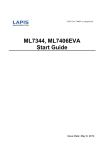
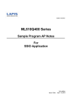
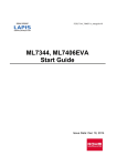
1
FEXL7396_EVA_startguide-03
ML7396 Family LSI Evaluation Kit
Start Guide
※ Please read first
Data: Feb 28, 2013
ML7396 Family Evaluation Kit StartGuide
Introduction
Thank you very much for purchasing products of our company. Before using this product, please use
correctly after reading this “start guide”. Moreover, please keep it carefully even after reading this.
This start guide indicates enclosure attachment ant the connection method.
The manual shown in the following other than this document is prepared. Please check if needed.
ML7396 or ML7396A_B_E Datasheet
ML7396 Family LSI Design Guide
ML7396 Family LSI simple MAC User’s Manual
1
ML7396 Family Evaluation Kit StartGuide
Notation
Classification
Notation
z Numeric value
0xnn
0bnnnn
Represents a hexadecimal number.
Represents a binary number.
z Address
0xnnnn_nnnn
Represents a hexadecimal number. (indicates 0xnnnnnnnn)
z Unit
word, W
byte, B
Mega, M
Kilo, K (uppercase)
Kilo, k (lowercase)
Milli, m
Micro, μ
Nano, n
Second, s (lowercase)
1 word = 32 bits
1 byte = 8 bits
106
210=1024
103=1000
10-3
10-6
10-9
Second
z Term
"H" level
Signal level on the high voltage side; indicates the voltage level of
VIH and VOH as defined in electrical characteristics.
Signal level on the low voltage side; indicates the voltage level of VIL
and VOL as defined in electrical characteristics.
"L" level
Description
z Register description
Read/write attribute: R indicates read-enabled; W indicates write-enabled.
MSB: Most significant bit in an 8-bit register (memory)
LSB: Least significant bit in an 8-bit register (memory)
2
ML7396 Family Evaluation Kit StartGuide
Table of Contents
1. Attention on the handling of this product ............................................................................................................... 4
2. Setup Flow ................................................................................................................................................................. 5
STEP1
STEP2
STEP3
CHECK THE CONTENTS OF PACKING.............................................................................................................5
CONNECT EVALUATION BOARD AND MCU BOARD ........................................................................................ 6
SETUP SERIAL COMMUNICATION SOFTWARE ................................................................................................ 7
REVISION HISTORY ................................................................................................................................................. 10
■NOTES....................................................................................................................................................................... 11
3
ML7396 Family Evaluation Kit StartGuide
1. Attention on the handling of this product
・
・
・
・
・
・
This product is evaluation kit. It is available for evaluation only.
Please use the application software of this product with the PC with which Japanese version Windows XP is installed.
It will become infringement of copyright, if all or apart of software of this product is reproduced without permission of
copyright or duplicate things are distributed.
Any responsibility cannot be taken about reconstruction and illegal use of this product.
If the example of a harmful electric wave interference should occur from this product, please change operating frequency
promptly, or suspend the output of an electric wave, and perform disposal for interference evasion etc.
The evaluation board at the time of shipment is set as the constant of the data rate of 200kbps or less, and a 920MHz band.
When evaluated except this conditions, please use it after changing a constant with reference to a design guide.
4
ML7396 Family Evaluation Kit StartGuide
2. Setup Flow
This is flow from check of contents of packing to an assembly
STEP 1
Check the contents of packing
STEP 2
Connect evaluation board and MCU board
STEP 3
Setup serial communication soft-ware
STEP1
Check the contents of packing
Please check when open the box and all the following articles are assembled first.
If it should run short or should have damaged, please inform a purchasing agency.
*1
*2
*3
CD-ROM and BNC cable are packed only when first time purchase. BNC cable is used when BER measurement.
By shipment time, mounting parts etc may differ from a photograph in part.
Please prepare a stabilized power supply, a RS-232C cable(straight), and serial communication software(TeraTerm).
□
ML7396 Evaluation Board…1
□
□
Rohm/Lapis Semiconductor MCU Board…1
(ML610Q482 Reference Board)
Power Supply Cable…1
□
CD-ROM…1
(First time purchase only)
□
5
BNC Cable…2
(First time purchase only)
ML7396 Family Evaluation Kit StartGuide
STEP2
Connect evaluation board and MCU board
This chapter explains the connection method of an evaluation board and a MCU board.
*1
When you connect each boar or you remove, please be sure to operate by power supply OFF state.
Please connect the connector of an evaluation board and a MCU board as shown in below figure.
*2
*3
If a board is put aslant, there is risk of breakage of a connector.
If it is made to fall where a MCU board is put in an evaluation board or a strong shock is given, there is risk of
breakage of a connector. After use, please remove and keep an evaluation board from a MCU board.
Connector of
evaluation board
Connector of MCU
board
Evaluation Board
MCU Board
After connection
Connect evaluation board and MCU board
6
ML7396 Family Evaluation Kit StartGuide
STEP3
Setup serial communication software
This chapter explains the setup of serial communication software used for operation of an evaluation kit.
(Note) Tera Term(Freeware) is recommended as serial communication software.
The macro used by simple MAC is described by the macro language of Tera Term.
Please download before beginning this operation.
1.
Install Tera Term to a PC which is used for evaluation.
2.
Connect Evaluation board and MCU board.
3.
Connect MCU board to a PC which Tera Term is installed by a RS-232C cable(Straight).
4.
Start Tera Term.
After start, the screen shown in Fig.1 is displayed.
Fig.1 Tera Term start up screen
5.
Select “Serial”, and select COM port from “Port:” box.
6.
After starting, select ”Setup” Menu => “Serial port…”, change setup into reference for Fig.2, and push the “OK”
botton.
Setting valu Baud Rate:
38400
Data:
8 bit
Parity:
none
Stop:
1 bit
Flow Control:
hardware
7.
Select “Setup” Menu => “Terminal…”, change setup into reference for Fig.2, and push the “OK” botton.
Setting value New Line
Recei ve:
CR+LF
Transmit:
CR
Local echo:
Check ON
7
ML7396 Family Evaluation Kit StartGuide
Terminal setting screen
Serial port setting screen
Fig.2 Tera Term communication setting
8
ML7396 Family Evaluation Kit StartGuide
8.
Turn on power supply of evaluation board.
9.
Input “RREG 6C” from serial communication software.
If “OK 88” is displayed as shown in Fig.3, connection is success.
Fig.3 After input “RREG 6C”
Preparation of this product is completion above.
After this preparation, please carry out a communication test and check the connection state, and operating correctly, after
referring to an attached simple MAC user’s manual.
9
ML7396 Family Evaluation Kit StartGuide
REVISION HISTORY
Document
No.
Date
Page
Previous
Edition
Current
Edition
Description
FEXL7396 EVA_
startguide-01
–
–
–
–
FEXL7396 EVA_
startguide-02
–
–
–
–
FEXL7396 EVA_
startguide-03
Feb 27, 2013
–
–
(Note)
First edition
Corrections in spelling, improvements in the description are not included in the Revision history.
10
ML7396 Family Evaluation Kit StartGuide
■NOTES
No copying or reproduction of this document, in part or in whole, is permitted without the consent of LAPIS Semiconductor Co.,
Ltd.
The content specified herein is subject to change for improvement without notice.
The content specified herein is for the purpose of introducing LAPIS Semiconductor's products (hereinafter "Products"). If you
wish to use any such Product, please be sure to refer to the specifications, which can be obtained from LAPIS Semiconductor
upon request.
Examples of application circuits, circuit constants and any other information contained herein illustrate the standard usage and
operations of the Products. The peripheral conditions must be taken into account when designing circuits for mass production.
Great care was taken in ensuring the accuracy of the information specified in this document. However, should you incur any
damage arising from any inaccuracy or misprint of such information, LAPIS Semiconductor shall bear no responsibility for such
damage.
The technical information specified herein is intended only to show the typical functions of and examples of application circuits
for the Products. LAPIS Semiconductor does not grant you, explicitly or implicitly, any license to use or exercise intellectual
property or other rights held by LAPIS Semiconductor and other parties. LAPIS Semiconductor shall bear no responsibility
whatsoever for any dispute arising from the use of such technical information.
The Products specified in this document are intended to be used with general-use electronic equipment or devices (such as audio
visual equipment, office-automation equipment, communication devices, electronic appliances and amusement devices).
The Products specified in this document are not designed to be radiation tolerant.
While LAPIS Semiconductor always makes efforts to enhance the quality and reliability of its Products, a Product may fail or
malfunction for a variety of reasons.
Please be sure to implement in your equipment using the Products safety measures to guard against the possibility of physical
injury, fire or any other damage caused in the event of the failure of any Product, such as derating, redundancy, fire control and
fail-safe designs. LAPIS Semiconductor shall bear no responsibility whatsoever for your use of any Product outside of the
prescribed scope or not in accordance with the instruction manual.
The Products are not designed or manufactured to be used with any equipment, device or system which requires an extremely
high level of reliability the failure or malfunction of which may result in a direct threat to human life or create a risk of human
injury (such as a medical instrument, transportation equipment, aerospace machinery, nuclear-reactor controller, fuel-controller
or other safety device). LAPIS Semiconductor shall bear no responsibility in any way for use of any of the Products for the
above special purposes. If a Product is intended to be used for any such special purpose, please contact a ROHM sales
representative before purchasing.
If you intend to export or ship overseas any Product or technology specified herein that may be controlled under the Foreign
Exchange and the Foreign Trade Law, you will be required to obtain a license or permit under the Law.
Copyright 2013 LAPIS Semiconductor Co., Ltd.
11