1
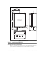
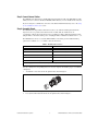
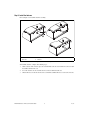
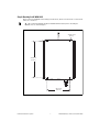
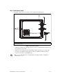
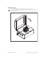
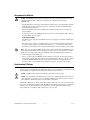
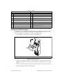
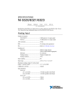
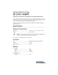
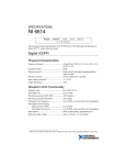
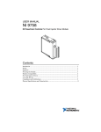
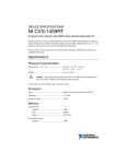
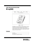
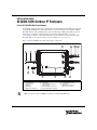
INSTALLATION GUIDE NI WSN-3295 Outdoor IP Enclosure For the NI 9792 WSN Real-Time Gateway This installation guide describes how to install and use the National Instruments WSN-3295 outdoor IP enclosure. The NI WSN-3295 outdoor IP enclosure is an accessory that provides the NI 9792 WSN Real-Time Gateway with a minimum ingress protection (IP) rating of IP65 against dust and water in harsh outdoor or industrial environments. For more information about IP ratings, refer to the Understanding IP Ratings section. For the NI 9792 device specifications, refer to the NI 9792 WSN Real-Time Gateway User Guide and Specifications available at ni.com/manuals. Figure 1 shows the NI WSN-3295 outdoor IP enclosure components. 4 2 1 14 7 8 13 Antenna IP Sleeve 2.4 GHz Antenna Antenna IP Boot Lock Nuts Gland Shells Gland Inserts, Reduced 7 8 9 10 11 Gland Inserts, Standard Gland Plugs Ethernet Field Termination Connector Kit 10 Ethernet Interface Connector 11 Internal RJ45 Ethernet Cable 12 13 14 — 9 Internal Antenna Cable Connector No-Crimp Ethernet Plug 4-40 Screws Quick Release Latches on Enclosure (not shown) Figure 1. NI WSN-3295 Outdoor IP Enclosure Components Note 6 3 12 1 2 3 4 5 6 5 You need a #1 and a #2 Phillips screwdriver to install the NI WSN-3295. The NI WSN-3295 kit includes the following items: • NI WSN-3295 • • Two M16 gland shells Two gland inserts, standard size • • • • • • • • • • • • • • • Two gland inserts, reduced size Two gland plugs Two lock nuts 2.4 GHz antenna Antenna IP boot Antenna IP sleeve One internal antenna cable connector (pre-installed) No-crimp Ethernet plug Four 4–40 stainless steel screws (to mount the NI 9792) Four 10–32 internal mounting plate screws (pre-installed) One aluminum mounting plate (pre-installed) One Ethernet field termination connector kit One Ethernet interface connector (pre-installed) One Ethernet end cap One internal RJ45 Ethernet cable (pre-installed) Dimensions Figure 2 shows the NI WSN-3295 dimensions. Caution When mounting the NI WSN-3295, allow at least 72.6 mm (3 in.) of clearance next to the enclosure quick release latches so you can open the enclosure if needed. NI WSN-3295 Outdoor IP Enclosure Installation Guide 2 ni.com 143.5 mm (5.65 in.) 66.86 mm (2.633 in.) 343.15 mm (13.51 in.) 5.84 mm (0.23 in) 56.85 mm (2.238 in.) 180.59 mm (7.11 in.) 287.02 mm (11.3 in.) Figure 2. NI WSN-3295 Dimensions Setting Up and Installing the NI WSN-3295 Complete the following steps to set up and install the NI WSN-3295. Step 1: Unpack and Inspect the Kit Contents Remove the device from the package and inspect the device and kit contents. Contact NI if the device appears damaged. Do not install a damaged device or use kit contents that appear damaged. © National Instruments Corporation 3 NI WSN-3295 Outdoor IP Enclosure Installation Guide Step 2: Install the NI 9792 WSN Real-Time Gateway Complete the following steps to install the NI 9792 WSN Real-Time Gateway: 1. Open the quick release latches on the NI WSN-3295 cover. 2. The NI WSN-3295 ships with an installed internal mounting plate. Remove the plate by unscrewing the 10–32 screws. 3. Mount the NI 9792 WSN Real-Time Gateway to the internal mounting plate using the included 4–40 screws. Caution 4. Using screws longer than 4–40 can damage the NI 9792 WSN Real-Time Gateway. Reinstall the internal mounting plate with the attached NI 9792 WSN Real-Time Gateway into the enclosure using the 10–32 screws as shown in Figure 3. 2 1 1 4–40 Screws 2 10–32 Screws Figure 3. Installing the NI 9792 Real-Time Gateway NI WSN-3295 Outdoor IP Enclosure Installation Guide 4 ni.com Step 3: Connect Internal Cables The NI WSN-3295 ships with a pre-installed IP-rated internal antenna cable and a RJ45 Ethernet cable, which you need to connect to the NI 9792 WSN Real-Time Gateway once it is installed in the enclosure. If you are using the second Ethernet connection on the NI 9792 Real-Time Gateway, refer to the Using the Second Ethernet Connection section. Step 4: Assemble Glands The NI WSN-3295 ships with two different insert sizes to use with the included gland shells. The larger insert can accept cables with a diameter from 4–8 mm, while the smaller insert can accommodate cables from 2–6 mm. For the larger 4–8 mm insert, NI recommends the Ethernet cable (NI part number: 182219-05) and the power cord (NI part number: 780703-01) available from ni.com. The NI WSN-3293 inserts accessory kit (NI Part Number: 195738-01) provides additional wiring options and is available at ni.com. Table 1 shows the insert sizes. Table 1. NI WSN-3293 Insert Sizes * Number of Holes Wire Size 2 3 mm 4 1.7 mm 6 1.4 mm 10 1.4 mm Solid Plug* — The solid plug can be frozen and drilled to any size and configuration needed. Once the cable(s) and corresponding inserts are selected, complete the following steps to assemble the cable glands: 1. Assemble the selected inserts into the gland shell as shown in Figure 4. Figure 4. Assembling Insert into Gland Shell 2. Loosely thread the included lock nut onto the gland shell as shown in Figure 7. © National Instruments Corporation 5 NI WSN-3295 Outdoor IP Enclosure Installation Guide Step 5: Install the Antenna Refer to Figure 5 to install the antenna assembly. 1 4 2 3 5 1 2 IP Boot Enclosure 3 4 External Antenna Connector Antenna 5 IP Sleeve Figure 5. Antenna Assembly Installation To install the antenna, complete the following steps: 1. On the outside of the enclosure, place the antenna IP boot onto the external antenna connector with the smaller diameter hole out. 2. Screw the antenna onto the external antenna connector until it bottoms out. 3. Slide the IP sleeve down the antenna and over the IP boot until the IP sleeve touches the enclosure. NI WSN-3295 Outdoor IP Enclosure Installation Guide 6 ni.com Step 6: Mounting the NI WSN-3295 Figure 6 shows the NI WSN-3295 mounting hole dimensions, which are molded on the enclosure back surface for convenience. Tip NI recommends installing the NI 9792 WSN Real-Time Gateway before mounting the NI WSN-3295, as shown in Figure 3. 4X Ø 8.13 mm (0.32 in.) 324.36 mm (12.77 in.) 203.71 mm (8.02 in.) Figure 6. NI WSN-3295 Mounting Hole Dimensions and Locations © National Instruments Corporation 7 NI WSN-3295 Outdoor IP Enclosure Installation Guide Step 7: Install External Cables To install the external cables, refer to Figure 7 while completing the following steps: 1 2 3 1 2 Lock Nut Outer Compression Nut 3 Ethernet Field Termination Cable Figure 7. External Cable Installation 1. Tighten the lock nut to approximately 3.75 N · m (33.2 lb · in.) ensuring that the O-ring is pressed flat against the enclosure wall. 2. Tighten the outer compression nut to approximately 2.50 N · m (22.1 lb · in.) to seal the cable. 3. Attach the external Ethernet field termination cable to the NI WSN-3295 Ethernet interface connector on the outside of the NI WSN-3295. Note A preassembled IP-rated 5 meter RJ45 Ethernet cable (NI part number: 196650-05) is available from ni.com. NI WSN-3295 Outdoor IP Enclosure Installation Guide 8 ni.com Step 8: Attach the Cover The cover of the NI WSN-3295 is equipped with quick release latches (not shown). Tip You can prevent tampering with the enclosure contents by placing a lock through the holes in the quick release latches. Figure 8. Attaching the NI WSN-3295 Cover © National Instruments Corporation 9 NI WSN-3295 Outdoor IP Enclosure Installation Guide Environmental Limitations Caution The NI WSN-3295 is intended for outdoor use in most environments, but does have the following limitations. NI recommends accounting for these limitations when using the NI WSN-3295. • The NI WSN-3295 is rated for an external ambient of 60 ºC when in use with the NI 9792 WSN Real-Time Gateway. Exceeding this temperature could damage the NI 9792 WSN Real-Time Gateway internal components. • Placing the NI WSN-3295 in direct sunlight causes the internal temperature to rise above the outdoor ambient. • If AC power is desired, the NI WSN-3295 is also rated for an external ambient of 60 ºC when in use with a NI PS-15 power supply. NI PS-15 Power Supply The NI PS-15 power supply and the NI PS-15/16/17 power supply panel mount is available from from ni.com. The NI PS-15 Power Supply User Manual and Specifications and NI PS-15/16/17 Panel Mount Brackets Installation Guide are available for download at ni.com. The NI PS-15/16/17 Panel Mount Brackets Installation Guide contains mounting dimensions for the NI PS-15 power supply. Note The screws to mount the NI PS-15/16/17 power supply panel mount to the NI WSN-3295 are not included with the NI PS-15/16/17. You will need 4 10-32 x 1/2” screws with nuts to attach the NI PS-15 power supply panel mount to the NI WSN-3295 internal mounting plate. NI does not recommend tapping the mounting plate. • There is enough room in the NI WSN-3295 for additional components if you want to add them. Note that the tested thermal rating of 60 ºC external ambient applies when the enclosure contains the NI 9792 WSN Real-Time Gateway with or without the PS-15 power supply. NI does not guarantee a 60 ºC external ambient when additional components are added to the enclosure. Understanding IP Ratings Proper use and installation of an NI 9792 WSN Real-Time Gateway in an NI WSN-3295 outdoor IP enclosure provides a minimum IP rating of IP65 from harsh outdoor and industrial environments. An IP rating of IP65 protects against entry by dust particles and low pressure water jets. Caution This IP65 rating is National Instruments self-declared enclosure rating. Caution If you would like to modify the IP enclosure to have an additional gland or IP connector, ensure that these components are rated to a minimum of IP65 for the temperature range of –40 ºC to 60 ºC. Otherwise, the IP rating of the enclosure will be compromised. An IP rating of IP65 protects against entry by dust particles and low pressure water jets. The two-digit ingress protection (IP) rating is defined by the IEC 60529 standard and specifies the degree to which the enclosures protect against the intrusion of solid particles (represented by the first digit) and water (represented by the second digit). Table 2 lists the degree of protection. NI WSN-3295 Outdoor IP Enclosure Installation Guide 10 ni.com Table 2. IP Ratings First Number (Protection Against Solid Objects) Second Number (Protection Against Water) 0 No protection 0 No protection 1 Protects against objects greater than 50 mm 1 Protects against vertically dripping water 2 Protects against objects greater than 12.5 mm 2 Protects against direct sprays up to 15° from vertical 3 Protects against objects greater than 2.5 mm 3 Protects against direct sprays up to 60° from vertical 4 Protects against objects greater than 1 mm 4 Protects against direct sprays from all angles 5 Dust-protected (no harmful deposit) 5 Protects against low pressure water jets 6 Dust-tight 6 Protects against high pressure water jets — — 7 Immersible in water up to 1 m — — 8 Immersible in water beyond 1 m Using the Second Ethernet Connection If you want to use the second Ethernet connection and maintain your IP rating, you need to use the no-crimp Ethernet plug included with the NI WSN-3295 to build an Ethernet cable for the second connection. Complete the following steps to use the no-crimp Ethernet plug: 1. Run your Ethernet cable through the glands into the NI WSN-3295. 1 1 Wire Connection Figure 9. No-Crimp Ethernet Plug 2. Attach the no-crimp Ethernet plug to your cable by lining the colored wires up with the chart on the inside of the plug. Use the A chart for older CAT5 cables or the B chart for most new CAT5e cables. 3. Insert the wires into the tunnels, ensuring that they protrude all the way to the back of the plug. 4. Finish by snapping the lid shut as shown in Figure 9. © National Instruments Corporation 11 NI WSN-3295 Outdoor IP Enclosure Installation Guide 5. To verify that all the wires are properly connected, use a DMM to check connectivity. 6. After you have attached the no-crimp Ethernet plug to the cable, plug the Ethernet cable into the second Ethernet port in the NI 9792 WSN Real-Time Gateway. For information about wiring power, refer to the NI 9792 WSN User Guide and Specifications. Environmental Management National Instruments is committed to designing and manufacturing products in an environmentally responsible manner. NI recognizes that eliminating certain hazardous substances from our products is beneficial to the environment and to NI customers. For additional environmental information, refer to the NI and the Environment Web page at ni.com/ environment. This page contains the environmental regulations and directives with which NI complies, as well as other environmental information not included in this document. Waste Electrical and Electronic Equipment (WEEE) EU Customers At the end of the product life cycle, all products must be sent to a WEEE recycling center. For more information about WEEE recycling centers, National Instruments WEEE initiatives, and compliance with WEEE Directive 2002/96/EC on Waste and Electronic Equipment, visit ni.com/environment/weee. ⬉ᄤֵᙃѻક∵ᶧࠊㅵ⧚ࡲ⊩ ˄Ё RoHS˅ Ёᅶ᠋ National Instruments ヺড়Ё⬉ᄤֵᙃѻકЁ䰤ࠊՓ⫼ᶤѯ᳝ᆇ⠽䋼ᣛҸ (RoHS)DŽ ݇Ѣ National Instruments Ё RoHS ড়㾘ᗻֵᙃˈ䇋ⱏᔩ ni.com/environment/rohs_chinaDŽ (For information about China RoHS compliance, go to ni.com/environment/rohs_china.) Where to Go for Support The National Instruments Web site is your complete resource for technical support. At ni.com/ support you have access to everything from troubleshooting and application development self-help resources to email and phone assistance from NI Application Engineers. National Instruments corporate headquarters is located at 11500 North Mopac Expressway, Austin, Texas, 78759-3504. National Instruments also has offices located around the world to help address your support needs. For telephone support in the United States, create your service request at ni.com/ support and follow the calling instructions or dial 512 795 8248. For telephone support outside the United States, visit the Worldwide Offices section of ni.com/global to access the branch office Web sites, which provide up-to-cate contact information, support phone numbers, email addresses, and current events. LabVIEW, National Instruments, NI, ni.com, the National Instruments corporate logo, and the Eagle logo are trademarks of National Instruments Corporation. Refer to the Trademark Information at ni.com/trademarks for other National Instruments trademarks. Other product and company names mentioned herein are trademarks or trade names of their respective companies. For patents covering National Instruments products/technology, refer to the appropriate location: Help»Patents in your software, the patents.txt file on your media, or the National Instruments Patent Notice at ni.com/patents. Refer to the Export Compliance Information at ni.com/legal/ export-compliance for the National Instruments global trade compliance policy and how to obtain relevant HTS codes, ECCNs, and other import/export data. © 2011 National Instruments Corporation. All rights reserved. 373385A-01 Dec11