1
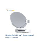
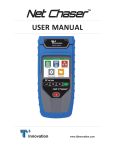
USER MANUAL
SMC55 CAMPING
Version 1.0 February 2012
Introduction
Congratulations on the purchase of your VISIOSAT CAMPING system.
This user manual provides all necessary information on the installation, operation and maintenance of your
system.
The SMC 55 CAMPING provides maximum freedom. For example, you can park your trailer or RV in the shadow
of a tree, position the system anywhere you like and fully enjoy your favorite television programs. The set up in a
snap, is very easy to operate and is connected to the system with a single cable. With just a push of a button, the
system automatically finds the satellite of your choosing. After the dish has been aligned, you can easily remove
the control module from the system for safe storage and continue watching television without interruption.
Where possible, high quality materials such as stainless steel and durable plastics are used to ensure a long
service life. There are no parts in the device that require servicing by the user.
WARNINGS AND REMARKS
The contents of this manual are up to date at the time of print. In no way VISIOSAT can be held liable for any
errors that may occurred while writing this manual.
VISIOSAT reserves the right to implement any modifications it deems necessary during the development of the
products, and to modify or change this installation and user manual and the herein described products without
prior notice.
Please first read this user manual before putting your system into operation. Follow all instructions and carefully
observe the directions presented in this manual.
Before taking the device into operation, first ensure that all cables have been connected correctly. Please note
that when you switch on the power supply and activate the satellite receiver, the satellite dish will begin rotating
within a few seconds. This is also indicated on the display of the control module.
Switch off and disconnect the power supply before you carry out any actions on the system. The control module is
splash-proof however it may not be cleaned with water.
Even without the control module, it is not recommended to clean the antenna with a high-pressure washer. Use a
soft and moist cloth with soap instead.
For additional information we kindly ask you to contact the specialist dealer where you purchased your system.
User manuals and software updates can be found on our website:
www.visiosat.com
Page
2
Table of contents
1.1
1.2
1.3
1.4
1.5
2.1
3.1
3.2
3.3
3.4
3.5
3.6
3.7
4.1
5.1
6.1
7.0
7.1
7.2
7.3
7.4
7.5
7.6
7.7
7.8
8.1
9.1
10.1
Safety instructions and warnings
...................................................................................................... 4
Tips before going on vacation ................................................................................................................... 4
SMC55 CAMPING package ...................................................................................................................... 4
Shipment check list ................................................................................................................................... 4
Components.............................................................................................................................................. 5
Control module.......................................................................................................................................... 6
Choosing a setup location ......................................................................................................................... 6
Placing the tripod ...................................................................................................................................... 7
Placing the antenna dish ........................................................................................................................... 7
Electric connection .................................................................................................................................... 8
Searching for the satellite.......................................................................................................................... 9
Special remarks on searching for the satellite......................................................................................... 12
Removing the control module.................................................................................................................. 12
Menu ....................................................................................................................................................... 13
Park position ........................................................................................................................................... 14
Stop button.............................................................................................................................................. 14
Error messages ....................................................................................................................................... 15
No satellite found, check manual ............................................................................................................ 15
Satellite found, but no picture.................................................................................................................. 15
Satellite found, but not all channels......................................................................................................... 15
Error PI Disconnected: ............................................................................................................................ 15
Error during software update:.................................................................................................................. 15
Error during software update:.................................................................................................................. 16
Error during software update:.................................................................................................................. 16
Error messages: calibration failed, error azimuth adjustment, error elevation adjustment ...................... 16
No LNB signal: ........................................................................................................................................ 16
Specifications .......................................................................................................................................... 16
Warranty conditions................................................................................................................................. 17
page 3
1.1
Safety instructions and warnings
Carefully read this user manual before using the device.
Scope of use
Your SMC55 CAMPING has been developed to automatically search and find a satellite signal. This device is
only intended for use by consumers and outdoors
For safe use, please observe the following:
Tripod
When extending or folding up the tripod, be careful not to pinch your hands between the legs of the tripod.
Handling the dish unit
Use the hand grip on the back of the dish unit when picking up the system for positioning or storage.
LNB arm
When folding down the LNB arm, ensure that your fingers do not become pinched in the hinge.
During alignment
Make sure not come into physical contact with the dish unit while it is aligning and rotating. Only use the control
module and make sure nothing and nobody enters the turning circle of the system during its alignment.
Connecting the system
Always first fully connect the system before switching on the power supply. Otherwise you risk receiving a slight
electric shock.
Coaxial cable
Ensure that when unrolling the system’s coaxial cable, it is laid down as flat as possible and that it is covered so it
does not pose a tripping hazard.
1.2
Tips before going on vacation
Check whether your subscription or smart cart is still valid.
Check the correct function of the system.
Check the website www.visiosat.com or ask your dealer for any software updates.
1.3
Packaging
The SMC55 CAMPING is packed in a cardboard box with the dimensions of 66x38x83 cm which is
protected on both sides with EPS foam.
•
•
1.4
Before opening the package we kindly request that you check the following:
The cardboard box may not be deformed and may not have serious and obvious signs of damage such
as cracks in the cardboard or dents resulting from impact.
The sealing tape on the package must be intact.
Shipment check list
The following parts should be included in the shipment:
• Antenna dish (complete antenna unit with LNB)
• Control module (display, holder with electronics and motors)
Page
4
•
•
•
•
•
•
1.5
Tripod
15 meters of coaxial cable with waterproof connectors
230-240V power adapter
Power inserter
20 cm coaxial cable (for the connection on the power inserter to the receiver)
User manual
Components of the SMC55 CAMPING
Antenna dish
LNB
Control module
Tripod
15m coaxial cable
20cm coaxial cable
Power inserter
230V power adapter
page 5
2.1
Control module
The control module has 4 functions:
•
Actuate
The build-in motors and electronics drive the system
•
Control
Sends commands to the antenna dish, e.g. satellite choice, parking, etc…
•
Display
indicates the system’s status on the display
•
Update
Replaces or updates the software
Control panel buttons:
1.
2.
3.
4.
5.
6.
7.
8.
Start (system starts searching for satellite)
Park (system places itself in the parked position)
Enter (select)
Arrow up
Arrow down
Escape (one step back)
Menu
Stop
9.
USB port
A USB port is located at the back of the control module to
carry out software updates
(see section 4.2 on how to update the software)
3.1
Choosing a setup location
Several factors must be considered when deciding on the location of where to set up the system:
•
•
•
The surface on which the antenna will be positioned should be reasonably flat.
The ideal location is a place where there is an unobstructed view in all directions.
When the view is obstructed, choose a location with an unobstructed view in the direction of the desired
satellite. This means that there should be no obstructions such as trees, trailers or RV’s, buildings, etc…
Page
6
3.2
Positioning the tripod
After choosing a suitable setup location, you can unfold and
position the tripod. Ensure that the legs are fully extended so
that the system will stand in a stable and rigid position.
Additionally, the legs can be secured by means of the supplied
pegs. Place the tripod on a surface that is as flat as possible.
The surface does not have to be perfectly horizontal, but the
more the unit is leveled, the quicker the system will locate the
satellite.
3.3
Placing the antenna dish
How to mount the antenna dish on the tripod:
Guide the rotation axle of the antenna dish into the plastic
socket of the tripod
Then slowly rotate the dish in either direction until the axle
has been fixed in the tripod.
Lower the LNB all the way down.
Ensure that the arm locates into its hinge ensuring that the
LNB is properly aligned with the antenna dish.
“click”
page 7
Before using the system, connect the cable with the Fconnector to the LNB and hand-tighten it. No tools are
required.
3.4
Electric connection
The system is connected with 2 coaxial cables. The long coaxial cable is mounted between the antenna unit
located outside and the power inserter located inside. The power inserter is connected to your receiver by means
of the short coaxial cable (receiver is not included).
The system operates on 24 volt. The required 24 volt is supplied by the power inserter with 230V power adapter.
By default, the system is suited for 1 receiver with unlimited channel reception from the chosen satellite.
Connection procedure:
Firmly press the F-connector of the coaxial cable over the connector
located on the bottom of the dish unit, so that the rubber is indented,
and hand-tighten it.
Press the F-connector on the other end of the coaxial cable over the
connector of the power inserter (indicated with “Antenna R6”), so that
the rubber is indented, and hand-tighten it.
Connect the short coaxial cable between the connector of the power
inserter (indicated with “Receiver”) and the “Antenna In” connector of
your receiver, and hand -tighten both items.
Page
8
Insert the power adapted jack plug (round plug) in the 24V port of the power inserter (indicated with “Power-in
24V”) and insert the power plug of the power adapter in a 230V wall outlet.
The system is now ready for use.
3.5
Searching satellite
After connecting the wiring as described in section 3.4, switch on your satellite receiver and television. Then
connect the control module to the antenna system by pressing it firmly into its socket.
WAITING FOR PI
On the display of the control module the following will be then shown:
RECREATION
FIRMWARE V****
BOOTING
This last message will disappear within a few seconds, after which the system will present the satellite menu. At
this level, you can select the satellite of your choosing.
ASTRA 1 19.2°
TURN LNB TO 0
∞
page 9
During its first usage, the system will preselect the Astra 1 satellite. The system will store and remember
previously selected satellite(s) and will show it on the display after startup.
List of preprogrammed satellites from which you can choose:
Satellite
Position
Satellite
Position
Astra 1
19,2 E
Sirius
5
E
Astra 3
23,5 E
Thor
1
W
Astra 2
28,2 E
Atlanticbird 3
5
W
W
Hotbird
13
E
Atlanticbird 2
8
Hellasat 2
39
E
Atlanticbird 1
12,5 W
Eurobird 9a
9
E
Telstar 12
15
W
Eutelsat W3A
7
E
Hispasat
30
W
You will see a blinking ∞ symbol on the right-hand side of the display that indicates the status of the GPS location.
As long as it is blinking, the system is searching for the GPS location. When the symbol is continuously displayed,
the system has determined its GPS location.
We recommend that you wait with the selection of the desired satellite until the system has determined the GPS
location. The time needed for the determination of the GPS location is approximately 1 minute (see also next
remark).
After determination of the correct GPS location, the system will be able to find the satellite more quickly. It also
provides for the opportunity to set the correct LNB to ensure position optimal reception.
The correct position of the LNB is shown on the display for each satellite, which may differ per selected satellite.
When the GPS location has not been found (yet), by default this position will be 0.
Remark:
In the case of a weak GPS signal, it might not be possible to determine the location, in which case the system can
be used as normal. However, finding the satellite will take longer and the optimal position of the LNB will not be
provided. If the GPS signal improves during satellite search, then the system will adjust automatically.
You can browse through the preprogrammed satellites step by step.
By means of the arrow buttons located on the control module (buttons
4 and 5), For each satellite, the correct LNB position is shown on the
display.
Page 10
Select the desired satellite, read off the corresponding LNB position from the display, and bring the LNB into this
position by turning the LNB holder accordingly (see images below).
LNB in position 0
After you have correctly positioned the LNB, press the Start button (1) to begin searching for the satellite.
The system will start the calibration within 5 seconds and search its vertical and horizontal reference points. The
following messages will be presented on the display:
.
CALIBRATING
PLEASE WAIT
CALIBRATING
ELEVATION
CALIBRATING
AZIMUTH
After this startup phase, the system will automatically begin its search for the selected satellite. For example:
ASTRA 1 19.2°E
SEARCH SATELLITE
Once the SMC55 CAMPING has found the satellite, it proceeds with an internal check followed by the
optimization of its alignment in small increments. This procedure will take about 2 minutes. The display will show
the following message:
ASTRA 1 19.2°E
OPTIMIZING
After completion of the optimization phase the system is aimed exactly at the satellite. The following messages
are provided:
page 11
ASTRA 1 19.2°E
OPTIMAL SIGNAL
LNB IN POSITION O
MODULE CAN BE
REMOVED
(Note: The mentioned LNB position is only an example.)
The signal is now transmitted to the connected satellite receiver and you can watch television. Remove the
control module for safe storage. Additionally the correct position of the LNB will be indicated.
3.6
Special remarks on searching for satellite
1.
With a weak GPS signal, it might be possible that the GPS location cannot be determined, in which case
the system can be used as normal. However, finding the satellite will take longer and the optimal position
of the LNB will not be provided.
2.
If you began searching for the satellite during the determination of the GPS location, then the system
could suddenly stop searching and show the following message:
OPTIMAL SIGNAL
LNB IN POSITION +3
This indicates that the system has found the GPS location and that the position of the LNB has to be
adjusted as shown on the display. If you do not adjust the LNB position, the system may not receive a
satellite signal.
Turn the LNB to the correct position and press the Start button (1) and then the system will resume
searching.
3.
When the system finds a satellite with the correct characteristics, the dish will stop rotating. But if the
system concludes it has not found the selected satellite after the internal check, the following message
will be shown:
ASTRA 1 19.2°
WRONG SATELLITE
The system will automatically resume searching for the selected satellite.
3.7
Removing the control module
A release pin is located on the bottom of the control module. Press this release pin to remove the control module.
The control module is unlocked after the release pen is pressed.
Page 12
Carefully remove the control module by pulling it to the right. Do this
gently to ensure that the current alignment of the dish is not altered.
Remark:
The control module is splash-proof so that you can align the system when it is raining. We recommend
that you remove the control module following each alignment of the system to prevent theft and possible
water damage.
4.1
Menu
The menu provides for optional settings, including:
1) Language
2) Firmware update
1)
Language
You can select Dutch, German, English or French as the user language.
SETTINGS:
LANGUAGE
Press the enter button
Select the respective language with the arrow buttons (4 and 5) and press Enter (3) for confirmation.
ENGLISH
2)
Firmware update
The SMC55 CAMPING searches for satellites based on various preprogrammed frequencies. These
frequencies have been carefully selected by VISIOSAT, but they are subject to change. When these
frequencies change, VISIOSAT will release new software so that the system can use the new
frequencies. This software is freely available for download at the website www.visiosat.com and at
your local dealer.
Download the software for your VISIOSAT system from the website and store it on a USB flash drive.
Insert the USB flash drive in the USB port located on the bottom of the control module (see section 2.1).
The software transfer is only possible when the system is fully connected.
Select the firmware menu with the Enter button (3)
SETTINGS:
FIRMWARE
Press Enter and the display will show the current installed software version number. Press Enter again,
and the following message will be displayed:
page 13
SETTINGS :
FIRMWARE UPDATE?
Press Enter again
ARE YOU SURE?
Select Yes and the system will be updated with the new software and will automatically reboot.
UPDATE
VISIOSAT
Remove the USB flash drive from the USB port. The system has now been updated with the new
software and is ready for use.
5.1
Park position
When storing the system, you should set it in the park position. In the park position the dish is rotated so
that the system is best suitable for storage.
Press on the blue park button (2) and you will see these messages:
CAUTION PARKING
IN ... SEC
SYSTEM
PARKED
MODULE CAN BE
REMOVED
Before storing the system, first disconnect the power supply before disconnecting the coaxial cable ans
disassembling the antenna with the tripod etc. (Optionally, a special bag is available in which you can store the
system).
6.1
Stop button
You can push the red Stop button(8) at any time and as a result, the system will stop all actions and will
start over by displaying the satellite choice menu
SYSTEM STOPPED
Page 14
7.0
Error messages
7.1
No satellite found, check manual
When the satellite has not been found, you will receive the following message:
SATELLITE
NOT FOUND
PLEASE CONSULT
MANUAL
1.
2.
Check whether there are any obstructions. (See section 2.1)
Check if the latest VISIOSAT software version has been installed for any possibly changed satellite
3.
frequencies. See www.visiosat.com or consult your dealer.
You are possibly outside the broadcast area of the desired satellite.
•
•
•
•
Satellite found, but no picture
Check the coaxial cable between the power inserter and your satellite receiver.
Check the connection cables between your satellite receiver and your television.
Switch the receiver and the television off and back on.
Check the user manuals of your satellite receiver and television.
7.2
7.3
Satellite found, but not all channels
Check whether your subscription or smart cart is still valid.
7.4
Error PI Disconnected:
ERROR
PI DISCONNECTED
The control module is unaware of the power inserter. Check all connectors and switch power off and
back on. Reinsert the control module.
7.5
Error during software update:
E:ERROR DURING
UPGRADE
Repeat the software update procedure
page 15
7.6
Error during software update:
E:FIRMWARE NOT
FOUND
Check if the software has been correctly stored on the USB flash drive.
7.7
Error during software update:
E:USB DISK NOT
FOUND
Insert the USB flash drive once more.
7.8
Error messages: calibration failed, error azimuth adjustment, error elevation adjustment
ERROR DURING
CALIBRATING
ERROR AZIMUTH
ADJUSTMENT
ERROR ELEVATION
ADJUSTMENT
Check that there are no obstructions which hinder the rotation or alignment of the dish. Remove the
control module from the antenna unit and reinsert it again.
8.1
No LNB signal:
NO LNB SIGNAL
Check if the F-connector to the LNB is connected and tightened.
Check if the LNB cable is damaged.
9.1
Specifications
Dish diameter
55 cm
Weight
7.4 kg
Packing dimensions and weight
66 x 38 x 83 cm
Approx. 10 kg
230 V AC to 24 V DC
Max. 950 mA
USB
75 Ω double shielded (15 m supplied by default)
1 satellite receiver
Power adapter
Power usage
Software update via
Wiring
Possible connections
Page 16
10.1
Warranty conditions
1.
Warranty is only applicable when the VISIOSAT system is set up properly and when it is used in
accordance with the procedures as described in this user manual.
2. Through strict quality control and high requirements set in regard to the utilized materials, VISIOSAT
guarantees delivery of a sound and functional the system.
3. Within 24 months after purchase and within 36 months after production, defects due to an error in
manufacturing and/or wrong materials which occurred during normal use will be resolved under the
hereafter defined warranty conditions.
4. Warranty applies only on presentation of (a copy of) the purchase receipt and after providing the serial
number, by the owner of the system.
5. Warranty is not transferable.
6. The holder of the SMC55 CAMPING system should at first observation of a defect immediately inform
the dealer and should enable the dealer to detect the defect.
7. Where in the judgments of the dealer a defect can be rectified on site, then the dealer is authorized to
carry out the rectification on site. In the event that this is impossible the dealer will, without creating any
obligation to temporarily install a replacement system, dismantle the system and take it to his premises
for repair, or following consultation with the help desk, send the system to VISIOSAT so that they can
carry out the repair.
8. VISIOSAT reserves the right to refer to third parties or to make use of their services in dealing with the
warranty or offering advice.
9. The warranty may only be called upon where all the warranty conditions have been met. Liability on the
part of VISIOSAT is therefore limited to the reimbursement of the costs of repair or the bearing of such
costs by VISIOSAT, or replacement of the system in whole or in part, or of the component in which the
defect has occurred, all entirely according to the opinion and judgment of VISIOSAT.
10. VISIOSAT reserve the right to judge, entirely in accordance with their own opinion, that a defect is
attributable to improper use and/or improper installation of the system, in which event all claims against
the warranty shall lapse and will therefore be rejected.
11. VISIOSAT shall not be responsible for the suitability of the system for any purpose other than that for
which VISOSAT has given undertakings in the Installation and User Manual. VISIOSAT will therefore
accept no liability whatsoever for any damage resulting from such use.
12. VISIOSAT shall not be liable for any defect in the system and/or its functionality where this is the
consequence of damaging external factors, or of the improper or incomplete functioning of third party
products and/or services, or the unavailability thereof. VISIOSAT will therefore accept no liability
whatsoever for any damage resulting from such use.
page 17